Eaton Cutler-Hammer RTHMFDA20100WSU User manual

Effective 6/01, Supersedes ATS-RMO4 dated June 2000
I.B. ATS-RM05
Cutler-Hammer
Instructions for Cutler-Hammer Residential
Automatic Transfer Switch


Effective 6/01
I.B. ATS-RM05 Page iii
All possible contingencies which may arise during installation, operation or maintenance, and all details and
variations of this equipment do not purport to be covered by these instructions. If further information is
desired by purchaser regarding his particular installation, operation or maintenance of particular equipment,
contact a Cutler-Hammer representative.
READ AND UNDERSTAND THE INSTRUCTIONS
CONTAINED HEREINAFTER BEFORE ATTEMPTING
TO UNPACK, ASSEMBLE, OPERATE OR MAINTAIN
THIS EQUIPMENT.
HAZARDOUS VOLTAGES ARE PRESENT INSIDE
TRANSFER SWITCH ENCLOSURES THAT CAN
CAUSE DEATH OR SEVERE PERSONAL INJURY.
FOLLOW PROPER INSTALLATION, OPERATION
AND MAINTENANCE PROCEDURES TO AVOID
THESE VOLTAGES.
TRANSFER SWITCH EQUIPMENT COVERED BY
THIS INSTRUCTION BOOK IS DESIGNED AND TEST-
ED TO OPERATE WITHIN ITS NAMEPLATE RAT-
INGS. OPERATION OUTSIDE OF THESE RATINGS
MAY CAUSE THE EQUIPMENT TO FAIL RESULTING
IN DEATH, SERIOUS BODILY INJURY AND/OR
PROPERTY DAMAGE. ALL RESPONSIBLE PERSON-
NEL SHOULD LOCATE THE DOOR MOUNTED
EQUIPMENT NAMEPLATE AND BE FAMILIAR WITH
THE INFORMATION PROVIDED ON THE NAME-
PLATE. A TYPICAL EQUIPMENT NAMEPLATE IS
SHOWN IN FIGURE 1.
Figure 1
Typical Automatic Transfer Switch Equipment Nameplate
Cutler-Hammer
Automatic Transfer Switch
ECat No: RTHMFDA20100WSU 9/95
GO No: 1/1
Item: 1
Poles: 2 Amps: 100 Volt: 240
Phase: 1 Hertz: 60 Wire: 3
!
WARNING

Effective 6/01
I.B. ATS-RM05
TABLE OF CONTENTS
Page
SECTION 1: INTRODUCTION
1.1 Preliminary Comments and Safety Precautions..................................................................................................1
1.1.1 Warranty and Liability Information..........................................................................................................1
1.1.2 Safety Precautions .................................................................................................................................1
1.2 General Information.............................................................................................................................................1
1.2.1 Design Configuration..............................................................................................................................2
1.3 Transfer Switch Catalog Number Identification...................................................................................................2
1.4 Environmental Conditions ...................................................................................................................................3
SECTION 2: RECEIVING, HANDLING AND STORAGE
2.1 Receiving.............................................................................................................................................................4
2.2 Handling..............................................................................................................................................................4
2.3 Storage ...............................................................................................................................................................4
SECTION 3: EQUIPMENT DESCRIPTION
3.1 Introduction..........................................................................................................................................................5
3.2 Options ...............................................................................................................................................................5
3.3 Standards............................................................................................................................................................5
SECTION 4: INSTALLATION AND WIRING
4.1 General ...............................................................................................................................................................7
4.2 Mounting Location...............................................................................................................................................7
4.3 Mounting Procedure............................................................................................................................................8
4.4 Power Cable Connections ..................................................................................................................................9
4.5 Wiring................................................................................................................................................................10
4.6 Installation.........................................................................................................................................................10
4.7 Engine Start Connection ...................................................................................................................................10
4.8 Preliminary Checks ...........................................................................................................................................10
4.9 Terminal Block Wire Installation and Removal .................................................................................................13
SECTION 5: FUNCTIONAL TESTING
5.1 Preliminary Checks ...........................................................................................................................................15
5.2 Energize the Switch...........................................................................................................................................15
5.3 Operational Checks...........................................................................................................................................15
Page iv

Effective 6/01
I.B. ATS-RM05 Page v
Page
SECTION 6: ADJUSTMENTS
6.1 Plant Exerciser PE Timer..................................................................................................................................16
6.1.1 Timer Programming..............................................................................................................................16
6.1.2 Provisions for Extended PE Memory....................................................................................................16
SECTION 7: MAINTENANCE
7.1 Introduction........................................................................................................................................................17
7.2 Procedures........................................................................................................................................................17
7.3 Maintenance Log ..............................................................................................................................................20

Effective 6/01
I.B. ATS-RM05
Page vi
LIST OF FIGURES
Figure Title Page
1-1 Typical Load Transfer Switch (circuit breaker type) Schematic.................................................................1
1-2 Typical Residential Automatic Transfer Switch..........................................................................................3
4-1 Dimensions and Plan View of Residential Automatic Transfer Switch (30 -100A)....................................7
4-2 Dimensions and Plan View of Residential Automatic Transfer Switch (150 -200A)..................................7
4-3 Cover Removal .........................................................................................................................................8
4-4 Deadfront Removal ...................................................................................................................................9
4-5 Cable Connections ....................................................................................................................................9
4-6 Typical installation of a residential or light duty automatic transfer switch ..............................................11
4-7 Typical installation of a residential or light duty automatic transfer switch ..............................................11
4-8 Diagram of Typical Installation (Critical Loads Only) ..............................................................................12
4-9 Diagram of Typical Installation (All Household Loads) ...........................................................................12
7-1 Wiring Diagram for Residential Automatic Transfer Switch ....................................................................18
LIST OF TABLES
Table Title Page
1.1 Transfer Switch Catalog Number Explanation...........................................................................................2
4.1 Wire Size for Automatic Transfer Switch...................................................................................................9
7.1 Periodic Maintenance Procedures...........................................................................................................19

Page 1
SECTION 1: INTRODUCTION
1.1 PRELIMINARY COMMENTS AND SAFETY
PRECAUTIONS
This technical document is intended to cover most
aspects associated with the installation, application,
operation and maintenance of the Residential Automatic
Transfer Switch. It is provided as a guide for authorized
and qualified personnel only. Please refer to the specific
WARNING and CAUTION in Section 1.1.2 before pro-
ceeding. If further information is required by the pur-
chaser regarding a particular installation, application or
maintenance activity, a Cutler-Hammer representative
should be contacted.
1.1.1 WARRANTY AND LIABILITY INFORMATION
No warranties, expressed or implied, including war-
ranties of fitness for a particular purpose of merchant-
ability, or warranties arising from course of dealing or
usage of trade, are made regarding the information, rec-
ommendations and descriptions contained herein. In no
event will Cutler-Hammer be responsible to the purchas-
er or user in contract, in tort (including negligence), strict
liability or otherwise for any special, indirect, incidental
or consequential damage or loss whatsoever, including
but not limited to damage or loss of use of equipment,
plant or power system, cost of capital, loss of power,
additional expenses in the use of existing power facili-
ties, or claims against the purchaser or user by its cus-
tomers resulting from the use of the information and
descriptions contained herein.
1.1.2 SAFETY PRECAUTIONS
All safety codes, safety standards and/or regulations
must be strictly observed in the installation, operation
and maintenance of this device.
THE WARNINGS AND CAUTIONS INCLUDED AS
PART OF THE PROCEDURAL STEPS IN THIS DOCU-
MENT ARE FOR PERSONNEL SAFETY AND PRO-
TECTION OF EQUIPMENT FROM DAMAGE. AN
EXAMPLE OF A TYPICAL WARNING LABEL HEAD-
ING IS SHOWN ABOVE TO FAMILIARIZE PERSON-
NEL WITH THE STYLE OF PRESENTATION. THIS
WILL HELP TO INSURE THAT PERSONNEL ARE
ALERT TO WARNINGS, WHICH APPEAR THROUGH-
OUT THE DOCUMENT. IN ADDITION, CAUTIONS
ARE ALL UPPER CASE AND BOLDFACE.
READ AND UNDERSTAND THE MATERIAL PRE-
SENTED IN THIS DOCUMENT BEFORE ATTEMPTING
INSTALLATION, OPERATION OR APPLICATION OF
THE EQUIPMENT. IN ADDITION, ONLY QUALIFIED
PERSONS SHOULD BE PERMITTED TO PERFORM
ANY WORK ASSOCIATED WITH THE EQUIPMENT.
ANY WIRING INSTRUCTIONS PRESENTED IN THIS
DOCUMENT MUST BE FOLLOWED PRECISELY.
FAILURE TO DO SO COULD CAUSE PERMANENT
EQUIPMENT DAMAGE.
1.2 GENERAL INFORMATION
Transfer switches are used to protect critical electrical
loads against loss of power. The load’s normal power
source is backed up by a secondary (emergency) power
source. A transfer switch is connected to both the nor-
mal and emergency power sources and supplies the
load with power from one of these two sources. In the
event that power is lost from the normal power source,
the transfer switch transfers the load to the secondary
(emergency) power source. Transfer can be automatic
or manual, depending upon the type of transfer switch
equipment being used. Once normal power is restored,
the load is automatically or manually transferred back to
I.B. ATS-RM05
Effective 6/01
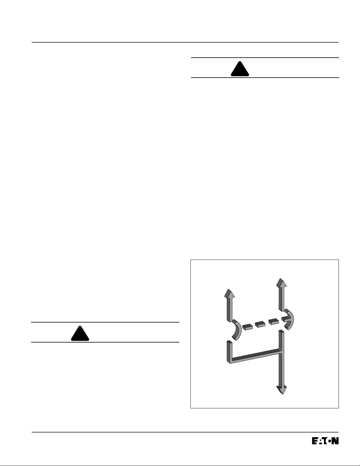
Figure 1-1 Typical Load Transfer Switch (circuit break-
er type) Schematic
Normal
Source
Emergency
Source
Load
!
WARNING
!
CAUTION

Page 2
the normal power source, again depending upon the
type of transfer equipment being used (Figure 1-1).
In automatic transfer switch equipment, the switch’s
intelligence system initiates the transfer when normal
power fails or falls below a preset voltage. If the emer-
gency power source is a standby generator, the transfer
switch initiates generator starting and transfers to the
emergency power source when sufficient generator volt-
age is available. When normal power is restored, the
transfer switch automatically transfers back and initiates
engine shutdown. In the event the normal power source
fails and the emergency power source does not appear,
the automatic transfer switch remains connected to the
normal power source until the emergency power source
does appear. Conversely, if connected to the emer-
gency power source and the emergency power source
fails while the normal power source is still unavailable,
the automatic transfer switch remains connected to the
emergency power source.
Automatic transfer switches automatically perform the
transfer function, and include three basic elements:
(1) Main contacts to connect and disconnect the load
to and from the source of power.
(2) A mechanism to make the transfer of the main con-
tacts from source to source.
(3) Intelligence/supervisory circuits to constantly moni-
tor the condition of the power sources and thus pro-
vide the intelligence necessary for the switch and
related circuit operation.
1.2.1 DESIGN CONFIGURATION
The Cutler-Hammer transfer switch is a rugged, com-
pact design that utilizes molded case switches to trans-
fer essential loads from one power source to another
(Figure 1-2). Molded case switches are interlocked to
prevent both switches from being closed at the same
time.
1.3 TRANSFER SWITCH CATALOG NUMBER
IDENTIFICATION
Transfer switch equipment catalog numbers provide a
significant amount of relevant information pertaining to a
specific piece of equipment. The Catalog Number
Identification Table (Table 1.1) provides the required
interpretation information. An example is offered to ini-
tially simplify the process.
Example: Catalog Number (circled numbers correspond
to position headings in Table 1.1)
The catalog number RTHMFDA20100WSU describes
an automatic transfer switch with the switching devices
mounted horizontally in the enclosure. The intelligence
I.B. ATS-RM05
Effective 6/01
Positions 1-2 Position 3 Position 4 Positions 5-6
Basic Switching Device Control Switching
Device Orientation Panel Device
Residential RT Horizontal HMicroprocessor MHFD Cutler-Hammer Series C FD
Position 7 Position 8 Positions 9-12 Position 13 Position 14 Position 15
Switching Device Number Ampere Voltage/
Arrangement of Poles Rating Frequency Enclosure Listing
Fixed Mount Molded Case ATwo 230A – 0030 240VAC/60Hz WNEMA 1 SUL Listed U
Switches 70A – 0070 208VAC/60Hz BNEMA 3R R
100A – 0100
150A – 0150
200A – 0200
Table 1.1
Transfer Switch Catalog Number Explanation
➀to ➁➂ ➃➄
to ➅➆ ➇ ➈
to ➉
RT H M FD A 2 0100 W S U
12 13 14 15

Effective 6/01
I.B. ATS-RM05 Page 3
represented by the control panel is microprocessor
logic. The frame is for 100 amp service, and the switch
is a 2-pole, fixed mount molded case switch. The contin-
uous current rating of this equipment is 100 amperes
and applicable at 240 VAC, 60Hz. The transfer switch
equipment is enclosed in a NEMA 1 enclosure and list-
ed for UL applications.
1.4 ENVIRONMENTAL CONDITIONS
Seismic
With proper installation and by including the appropriate
option which includes specially designed cleats, transfer
switches have a seismic capability which exceeds the
worst case Zone 4 required levels per both the Uniform
Building Code and the California Building Code.
Operational Conditions
Normally, a transfer switch is applied indoors in an elec-
trical equipment room. In the appropriate enclosure, it
can be used for outdoor applications where the equip-
ment is subject to falling rain, freezing temperatures and
95% humidity (non condensing). The ambient tempera-
ture range for operation is between -20 and +70°C.
Figure 1-2 Typical Residential Automatic Transfer
Switch (30-100A)

Effective 6/01
I.B. ATS-RM05
Page 4
SECTION 2: RECEIVING, HANDLING, AND
STORAGE
2.1 RECEIVING
Every effort is made to ensure that the transfer switch
equipment arrives at its destination undamaged and
ready for installation. Packing is designed to protect
internal components as well as the enclosure. Care
should be exercised, however, to protect the equipment
from impact at all times. Do not remove protective pack-
aging until the equipment is ready for installation .
When transfer switch equipment reaches its destination,
the customer should inspect the shipping container for
any obvious signs of rough handling and/ or external
damage that occurred during transportation. Record any
external and internal damage for reporting to the trans-
portation carrier and Cutler-Hammer, once a thorough
inspection is complete. All claims should be as specific
as possible and include Shop Order and General Order
numbers.
A shipping label affixed to the shipping container
includes a variety of equipment and customer informa-
tion, such as General Order number and Customer
Number. Make certain that this information matches
other shipping paper information.
Each transfer switch enclosure is packaged in its own
box. Heavy duty cardboard sides surround the enclo-
sure and are further supported with reinforced card-
board corner posts. A heavy duty cardboard lid which
will be used as a template for locating the mounting
holes covers the entire opening. Do not discard the
packing material until the equipment is ready for installa-
tion.
Once the top packaging is removed from the shipment,
the enclosure door can be opened. A plastic bag of doc-
uments will be found in the enclosure, usually attached
to the inside of the door. Important documents, such as
test reports, wiring diagrams, appropriate instruction
leaflets and a warranty registration card, are enclosed
within the bag and should be filed in a safe place.
2.2 HANDLING
As previously mentioned, transfer switch equipment is
packaged in its own box. Protect the equipment from
impact at all times and do not double stack. Once the
equipment is in the installation location and ready to be
installed, packaging material can be removed. Refer to
Section 4 of this manual for specific installation instruc-
tions.
2.3 STORAGE
Although well packaged, this equipment is not suitable
for storage outdoors. The equipment warranty will not
be applicable if there is evidence of outdoor storage. If
the equipment is to be stored indoors for any period of
time, it should be stored with its protective packaging
material in place. Protect the equipment at all times from
excessive moisture, construction dirt, corrosive condi-
tions, and other contaminants. It is strongly suggested
that the package-protected equipment be stored in a cli-
mate-controlled environment of -20°C to 65°C with a rel-
ative humidity of 80 percent or less. Do not under any
circumstance, stack other equipment on top of a transfer
switch equipment enclosure, whether packaged or not.

Effective 6/01
I.B. ATS-RM05 Page 5
SECTION 3: EQUIPMENT DESCRIPTION
3.1 INTRODUCTION
The Cutler-Hammer Residential Automatic Transfer
Switch is assembled and tested at the factory. It is
designed to be used in conjunction with standby power
distribution equipment to provide an alternate source of
power to critical circuits in the event that a primary
power source is interrupted.
This switch monitors both normal and standby power
sources and automatically transfers critical load circuits
between the two sources depending upon which source
is available. The normal source is preferred and will
remain connected to the switch if it is available.
3.2 OPTIONS
The following section describes the standard features in
the RTHM Transfer Switch. The time delays are not
adjustable.
1. Time Delay Normal to Emergency (TDNE)
This feature delays the transfer from the normal power
source to the emergency power source in order to over-
ride momentary normal power source outages and/or
fluctuations. Timing begins when the emergency power
source becomes available. It does not affect initiation of
the engine start circuit. Should the normal power source
fail, the engine start contact will close and, if connected
to an engine generator, will initiate an engine start-up in
10 seconds. The TDNE timer is set for 3 seconds.
2. Time Delay on Engine Starting (TDES)
This feature is used only where the emergency power
source is an engine generator. It delays initiation of the
engine start circuit in order to override momentary nor-
mal power source outages and/or fluctuations. It does
not affect the ability of the transfer switch to transfer
from the normal power source to the emergency power
source. The TDES timer is set for 10 seconds.
3. Time Delay Emergency to Normal (TDEN)
This feature delays transfer from the emergency power
source to the normal power source to allow the normal
power source to stabilize before the transfer is initiated.
Timing begins when the normal source becomes avail-
able. If the emergency power source fails during timing,
the time delay is overridden and an immediate transfer
to the normal power source will occur. The TDEN timer
is set for 7 minutes.
3.3 STANDARDS
Cutler-Hammer transfer switch equipment enclosed in a
NEMA 1 enclosure is listed for application by UL and
UL-C. In addition, Cutler-Hammer automatic transfer
switches are listed in File E38116 by Underwriters
Laboratories, Inc. under Standard UL 1008. This stan-
dard covers requirements for automatic transfer switch-
es intended for use in ordinary locations to provide light-
ing and power as follows:
a. In emergency systems, in accordance with articles
517 and 700 in the National Electrical Code,
ANSI/NFPA 70 and the National Fire Protection
Association No. 76A and/or
Failsafe
Failsafe refers to the condition whereby the transfer
switch is connected to the Emergency Source. In the
event that the Emergency Source fails and the Normal
Source is available, an immediate retransfer to the Nor-
mal Source shall occur.
4. Time Delay Engine Cool-Off
This feature allows the engine generator to run after the
transfer switch returns to the normal power source with-
out load. The TDEC timer is set for 5 minutes.
5B. Undervoltage /Underfrequency Sensing for
Emergency Source
This feature enables the logic to constantly monitor the
emergency power source. The logic prevents transfer
from the normal power source to the emergency source
until the emergency power source has reached an
acceptable operating voltage and frequency. Drop-out
is set at 80% of nominal voltage and pick-up is set at
90% of nominal voltage. Frequency drop-out is set at
58Hz and pick-up is set at 59 Hz.
23. Plant Exerciser
This feature is a 7-day timer and provides automatic
testing of the emergency source once each week, 15
minutes no load.
26. Undervoltage Sensing for Normal Source
This feature enables the logic to constantly monitor the
normal power source. The logic prevents transfer from
the emergency power source to the normal source until
the normal power source has reached an acceptable
operating voltage. Drop-out is set at 80% of nominal
voltage and pick-up is set at 90% of nominal voltage.

Effective 6/01
I.B. ATS-RM05
Page 6
b. In standby systems, in accordance with article 702
of the National Electrical Code and/or
c. In legally required standby systems in accordance
with article 701 of the National Electrical Code.
Cutler-Hammer automatic transfer switches are avail-
able to meet NFPA110 for emergency and standby
power systems, and NFPA99 for health care facilities
when ordered with the appropriate options.
Since Cutler-Hammer automatic transfer switches use
specially designed molded case switches as the main
power switching contacts, these devices must also be
listed under the additional UL Standard 1087.
Underwriters laboratories uses two basic types of listing
programs — label service and re-examination.
UL1087 employ a label service listing program which
requires an extensive follow-up testing program for list-
ed devices. Standard UL1008 for automatic transfer
switches lists devices under the reexamination program
which only requires a continual physical reexamination
of the components used in the product to ensure consis-
tency with the originally submitted device. Follow-up
testing is not required by UL1008.
Representative production samples of molded case
switches and molded case circuit breakers used in
Cutler-Hammer automatic transfer switches are subject-
ed to a complete test program identical to the originally
submitted devices on an ongoing periodic basis per
UL1087. The frequency of such a re-submittal can be as
often as every quarter for a low ampere device. Any fail-
ure during one of these periodic re-submittals could
result in a loss of the valued UL listing mark.

Effective 6/01
I.B. ATS-RM05 Page 7
SECTION 4: INSTALLATION AND WIRING
4.1 GENERAL
Transfer switches are factory wired and tested.
Installation requires solidly mounting the enclosed unit
and connecting power cables and auxiliary pilot circuits.
Physical mounting procedures and power cable connec-
tions are covered in this section. Once a transfer switch
is properly installed and wired, it should be mechanically
and electrically checked for proper installation and oper-
ation. The procedures for these initial mechanical and
electrical checks are outlined in Section 5 of this instruc-
tion manual.
4.2 MOUNTING LOCATION
Choose a location that offers a flat, rigid mounting sur-
face capable of supporting the weight of the enclosed
transfer switch equipment (Figure 4-1, 30-100A or
Figure 4-2, 150-200A). Avoid locations that are moist,
hot, or dusty, however, there are enclosure designs
available for special environments. If there are any
doubts as to location suitability, discuss it with your
Cutler-Hammer representative.
Check to make certain that there are no pipes, wires, or
other mounting hazards in the immediate mounting area
that could create a problem.
Figure 4-1 Dimensions and Plan View of Residential
Automatic Transfer Switch (in) (30-100A)
Figure 4-2 Dimensions and Plan View of Residential
Automatic Transfer Switch (in) (150-200A)
Weight 50lbs. (21kg.)
Weight 80lbs. (30kg.)
16.00
20.00
2.05
4.33
11.00
18.22
20.00
18.22
8.00
Back View Showing
Wall Mounting Dimensions
Back View Showing
Wall Mounting Dimensions
16.00
15.00
5.21
2.05
28.22
20.00
8.00

Effective 6/01
I.B. ATS-RM05
Page 8
Carefully remove all packing material from the transfer
switch at the mounting location. Do not discard the Top
Cardboard Pad. It is used as a template for locating the
mounting holes. Even though an equipment inspection
was made when the equipment was received, make
another careful inspection of the enclosure and the
enclosed transfer switch as packing material is removed
and the enclosure readied for mounting. Be especially
alert for distorted metal, loose wires or damaged
components.
4.3 MOUNTING PROCEDURE
EXTREME CARE SHOULD BE TAKEN TO PROTECT
THE TRANSFER SWITCH FROM DRILL CHIPS, FIL-
INGS AND OTHER CONTAMINANTS WHEN MAKING
THE CABLE ENTRY HOLES AND MOUNTING THE
ENCLOSURE TO PREVENT COMPONENT DAMAGE
OR A FUTURE MALFUNCTION .
The installation must comply fully with all applicable
codes, standards and regulations.
With the enclosed transfer switch equipment unpacked
and ready for mounting, proceed with these steps:
NOTICE
Step 1: Remove the 4 cover screws and place the
cover in a safe place (Figure 4-3).
Step 2: Before removing the 4 screws that hold the top
Dead Front cover in place, disconnect the 5
white plugs on the logic board. Care should be
taken when it is placed aside. Remove the 4
screws from the bottom Dead Front and place
it in a safe place (Figure 4-4).
Step 3: Depending upon customer preference and
Transfer Switch location, the knockouts may
be used or additional holes may be drilled for
cable entry and control wiring.
For control wiring (Generator start wiring), these
wires must be isolated from both power source
cables.
Step 4: Mount the switch to a rigid structure as close to
the electrical loads as possible. Use the card
board template provided to mark the mounting
pattern, and start the mounting hardware sev-
eral turns into the mounting structure. Lift the
switch over the embossed teardrop mounting
holes and secure the mounting screws.
Step 5: Connect cables as follows (Figure 4-5):
• NORMAL (utility) power cables to
terminals N1, N2.
• EMERGENCY (generator) power cables
to E1, E2.
• Customer load cables to T1, T2.
• NEUTRAL cable to Neutral terminal.
• GROUND wire to green 1/4-20 bolt.
Step 6: Generator start terminals are red and numbered
51, 52. They are located in the lower right hand
corner of the power panel, and used when the
generator has an automatic start feature.
Step 7: Tighten all cables and wiring to the specifictions
NOTICE
Figure 4-3 Cover Removal
4 Screws
!
CAUTION

Effective 6/01
I.B. ATS-RM05 Page 9
4.4 POWER CABLE CONNECTION
POWER CONDUCTORS MAY HAVE VOLTAGE PRE-
SENT THAT CAN CAUSE SEVERE PERSONAL
INJURY OR DEATH. DE-ENERGIZE ALL POWER OR
CONTROL CIRCUIT CONDUCTORS TO BE CON-
NECTED TO THE TRANSFER SWITCH EQUIPMENT
BEFORE BEGINNING TO WORK WITH THE CON-
DUCTORS AND/OR TERMINATING THEM TO THE
EQUIPMENT.
USE CABLE LUGS, NOT DESIGNED FOR THE
TRANSFER SWITCH MAY CAUSE HEATING PROB-
LEMS. BREAKER LUGS ONLY MOUNT TO THE
BREAKER, WHILE TRANSFER SWITCH LUGS
MOUNT TO BOTH THE BREAKER AND THE BUS-
BAR BEHIND THE BREAKER. FOR INSTALLATION
INSTRUCTIONS, REFER TO THE INSTRUCTION
LEAFLET SUPPLIED FOR THE SPECIFIC LUGS.
TO HELP PREVENT COMPONENT DAMAGE OR
FUTURE MALFUNCTIONS, USE EXTREME CARE TO
KEEP CONTAMINANTS OUT OF THE TRANSFER
SWITCH EQUIPMENT WHEN MAKING POWER
CABLE CONNECTIONS.
Test all power cables prior to connection to the unit to
ensure that conductors or cable insulation has not been
damaged while being pulled into position.
Power cables are to be connected to solderless screw
type lugs located on the transfer switch switching
devices. Verify that the lugs supplied will accommodate
the power cables being used. Also verify that the cables
comply with local electrical codes. Standard transfer
switch equipment, as supplied from the factory, will
accommodate the wire sizes shown in Table 4.1.
Carefully strip insulation from the power cables to avoid
nicking or ringing of the conductor strands. Prepare the
stripped conductor termination end by cleaning it with a
wire brush. If aluminum conductors are used, apply an
appropriate joint compound to the clean conductor sur-
face area.
Transfer Switch Number of
Amp Rating Wire Size Range Cables per Phase
30 - 100 #14 - 3/0 1
150 - 200 #6-300MCM 1
Table 4.1 Wire Size for Automatic Transfer Switch
Figure 4-4 Deadfront Removal Figure 4-5 Cable Connections
Ground Screw 51 52
Neutral
E1 E2 N1 N2
T1 T2
!
WARNING
!
CAUTION
!
CAUTION

Page 10 I.B. ATS-RM05
Effective 6/01
IMPROPER POWER CABLE CONNECTIONS CAN
CAUSE EXCESSIVE HEAT AND SUBSEQUENT
EQUIPMENT FAILURE.
Tighten cable lugs to the torque identified on the label
affixed to the unit immediately adjacent to the lugs.
4.5 WIRING
POWER CONDUCTORS AND CONTROL WIRING
MAY HAVE VOLTAGE PRESENT THAT CAN CAUSE
SEVERE PERSONAL INJURY OR DEATH. DE-ENER-
GIZE ALL POWER OR CONTROL CIRCUIT CONDUC-
TORS BEFORE BEGINNING TO PERFORM ANY
WIRING ACTIVITY TO OR WITHIN THE TRANSFER
SWITCH EQUIPMENT.
CHECK THE TRANSFER SWITCH EQUIPMENT
NAMEPLATE FOR RATED VOLTAGE. IT SHOULD
BE THE SAME AS THE NORMAL AND EMERGENCY
LINE VOLTAGES. OPERATING THE EQUIPMENT ON
IMPROPER VOLTAGE CAN CAUSE EQUIPMENT
DAMAGE.
4.6 INSTALLATION
In a typical installation for critical loads (Figure 4-6), the
automatic transfer switch (ATS) (1) and the generator (2)
are connected to the residential power supply. The ATS
(1) and emergency distribution panel (3) receive normal
power from a dedicated breaker in the utility service panel
(4). The ATS and emergency panel receive emergency
power from the generator (2). Power from the utility feeds
the utility panel.
When normal power fails, the ATS will sense the failure,
start the generator, and switch all loads to the emergency
panel. All emergency loads will receive power from the
generator. A line breaker is required between the emer-
gency source (generator) and the transfer switch (Figure
4-8). When normal power returns, the ATS will switch all
power back to the utility and shut down the generator.
In addition, another typical installation for household
loads can be considered (Figure 4-7). Refer to Figure
4-9 for a household loads connection diagram.
4.7 ENGINE START CONNECTION
The engine control contact connections are located on
the lower right of the intelligence portion of the ATS.
NOTE: Prior to making the engine start connection to
the switch, set the engine generator controls selector
switch in the OFF position to prevent an unwanted
engine start. Connect the engine start wires to the red
terminal blocks marked 51 and 52. A contact closes
between these terminal blocks when an engine start sig-
nal is provided by the ATS logic. The wiring diagram
(Figure 7-1) provides additional engine start connection
information.
4.8 PRELIMINARY CHECKS
After the ATS enclosure is installed and power cables
are connected to the equipment, thoroughly inspect the
unit to ensure that no tools were left inside and that the
cabinet is free of debris. If necessary, use a vacuum
cleaner to remove any and all construction or installation
debris from the equipment.
Read and understand all labels on the equipment.
Review and understand the wiring diagrams supplied
with the equipment. Note any optional accessories that
may have been furnished with this unit and review their
operation.
Verify that the phase-to-phase line voltages of both the
normal and emergency power sources are the same
and that they match rated voltage as indicated on the
ATS ratings label.
SEVERE EQUIPMENT DAMAGE CAN RESULT IF
UNIT IS NOT APPLIED AT PROPER VOLTAGE.
DO NOT ENERGIZE EQUIPMENT IF SUPPLY VOLT-
AGES DO NOT MATCH EQUIPMENT RATINGS
LABEL. CONTACT THE FACTORY FOR INSTRUC-
TIONS TO MODIFY THE VOLTAGE RATING IN THE
FIELD.
!
CAUTION
!
WARNING
!
CAUTION
!
CAUTION

Page 11
I.B. ATS-RM05
Effective 6/01
Figure 4-6 Typical installation of a residential or light duty automatic transfer switch. The switch (1) and generator (2)
are connected to the power supply. The automatic transfer switch is located between the emergency distribution (3)
and the utility panel (4).
Figure 4-7 Typical installation of a residential or light duty automatic transfer switch. The switch (1) and generator (2)
are connected to the power supply. The automatic transfer switch is located between the utility and the household
loads.
➀
➁
Main
Breaker
Panel
Transfer Switch
Disconnect
Switch
or Fuse Watt
Hour-
Meter
Generator
Power
Cables
Control
Wiring
Power
Cables
Control
Wiring

Page 12 I.B. ATS-RM05
Effective 6/01
Figure 4-8 Diagram of Typical Installation (Critical Loads Only)
Figure 4-9 Diagram of Typical Installation (All Household Loads)
Transfer Switch
Circuit Breaker
Watt-Hour Meter
Circuit Breaker
Main
Breaker
Panel
Emergency Source
Household Loads
(Typically included
in Genset)

Page 13
4.9 TERMINAL BLOCK WIRE INSTALLATION AND
REMOVAL
Proceed with the following steps and associated pic-
tures to install or remove terminal block wiring.
Step 1: Pictured above are two tension clamp terminal
blocks. There is a large one and small one, but the
operation is the same for both. A small tool, such as a
screwdriver, will be pushed into the square hole next to
the wire hole and a wire will be inserted into the larger
circular hole on the outer edge.
Step 2: Begin by inserting a small, flathead screwdriver
into the square (tool) hole with the flat surface of the
screwdriver against the back wall of the hole. With a lit-
tle bit of force, push the screwdriver in on a slight angle
toward the center of the clamp. Be sure to slide it in until
it clicks. You will then see the clamp open in the wire
hole.
Step 3: Once the screwdriver is in place, obtain a
stripped wire (strip about 1/4 of an inch) and insert it into
the larger circular wire hole. Push the wire in until it can
go no further.
Step 4: Next, while holding the wire in place, pull the
screwdriver out. The wire will now be held in securely.
Finally, pull on the wire to insure that it is correctly
inserted into the clamp.
Step 5: There are three additional pieces to these termi-
nal blocks. The plug and lock can only be used with the
large terminal block, while the yellow shorting strap can
be used for both.
I.B. ATS-RM05
Effective 6/01
Tool Hole Wire Hole
Shorting Strap
Plug Lock

Page 14
Step 6: To insert the shorting strap into the smaller ter-
minal block, place the strap into the small square holes
directly in the middle of the block. Then, push the short-
ing strap in until it snaps into place. When inserted cor-
rectly, the shorting strap will be a little below the top of
the terminal block.
Step 7: This picture shows the top of the large terminal
block, which has two small square holes in its center
(one is used for the shorting strap and the other hole is
for the lock). First, insert and push the shorting strap
into the square hole right next to the tool hole. When
the piece snaps into place, the top of it should lie a little
above the top of the terminal block.
Step 8: The lock can now be inserted. The pointed side
of the lock is the bottom and the flat side is the top.
With the overhanging part of the lock towards the pins
and the pointed side facing down, push the lock into the
small square holes next to the shorting strap. Make
sure that when this is being done, the shorting strap
does not stop the lock from being pushed all the way in.
If this is the case, the lock has been inserted backwards
and should be turned around. Once the lock has been
inserted correctly, it will snap into place.
Step 9: After the shorting strap and lock are in place, the
plug can be attached by sliding the single row of
holes at the bottom of the piece overtop the metal rods
of the terminal block. Match the rounded edge of the
plug with the rounded edge of the terminal block and
gently push the pieces together. The piece should snap
when correctly in place.
Step 10: Once the plug is snapped in place, the lock will
need to be pushed over it. In order to do this you can
either insert a flathead screwdriver into the small rectan-
gular hole at the top of the lock or you could squeeze
the lock and plug together using your fingers. When
using the screwdriver, insert it into the rectangular hole
of the lock, from the side opposite to the plug. Next
push the back of the screwdriver down (which will lift up
the top of the lock a little) and guide the lock overtop the
plug by pushing the screwdriver towards the plug.
When correctly together, it should now not be possible
to pull the plug out without removing the lock first.
Step 11: The picture above shows the exact position of
the additional pieces on the large terminal block. Once
they are in place, repeat steps 2) through 4) to correctly
wire the tension clamp terminal block. Note that the
square tool holes on the plug are facing the outside of
the assembly.
Step12: If these additional pieces would need to be
removed, you should do the following:
1.Remove the lock by inserting a screwdriver from the
same side as the plug into the small rectangular hole at
the top of the lock.
2. Push the screwdriver down and push it away from the
plug.
3. Pull the plug out.
I.B. ATS-RM05
Effective 6/01
Shorting Strap Hole
Lock Hole Shorting Strap Hole Tool Hole
Wire Holes
Tool Holes
Table of contents
Other Eaton Switch manuals

Eaton
Eaton Cutler-Hammer SPB User manual

Eaton
Eaton NZM3-XAV Manual

Eaton
Eaton PowerChain Management LCS Manual

Eaton
Eaton CEMU-01/03 Manual

Eaton
Eaton COOPER POWER SERIES Guide

Eaton
Eaton NHI-E-PKZ0 Series Manual

Eaton
Eaton LS ZB Series User manual

Eaton
Eaton TRIPP LITE Series User manual

Eaton
Eaton T0 NA Series Manual

Eaton
Eaton P3-63/I4 Manual

Eaton
Eaton XTCE095F F47 Series Manual

Eaton
Eaton MEM Memera User manual

Eaton
Eaton Magnum DS Instruction manual

Eaton
Eaton EGS Series User manual

Eaton
Eaton xComfort CTAA-02/02 User manual

Eaton
Eaton Cutler-Hammer ATVSKDA30300XSU User manual

Eaton
Eaton P3-/XM Manual

Eaton
Eaton Ulusoy URING12-24 F - SF6 User manual

Eaton
Eaton K1D Manual

Eaton
Eaton EATS16N User manual