manuals.online logo
Brands
  1. Home
  2. •
  3. Brands
  4. •
  5. Eaton
  6. •
  7. Switch
  8. •
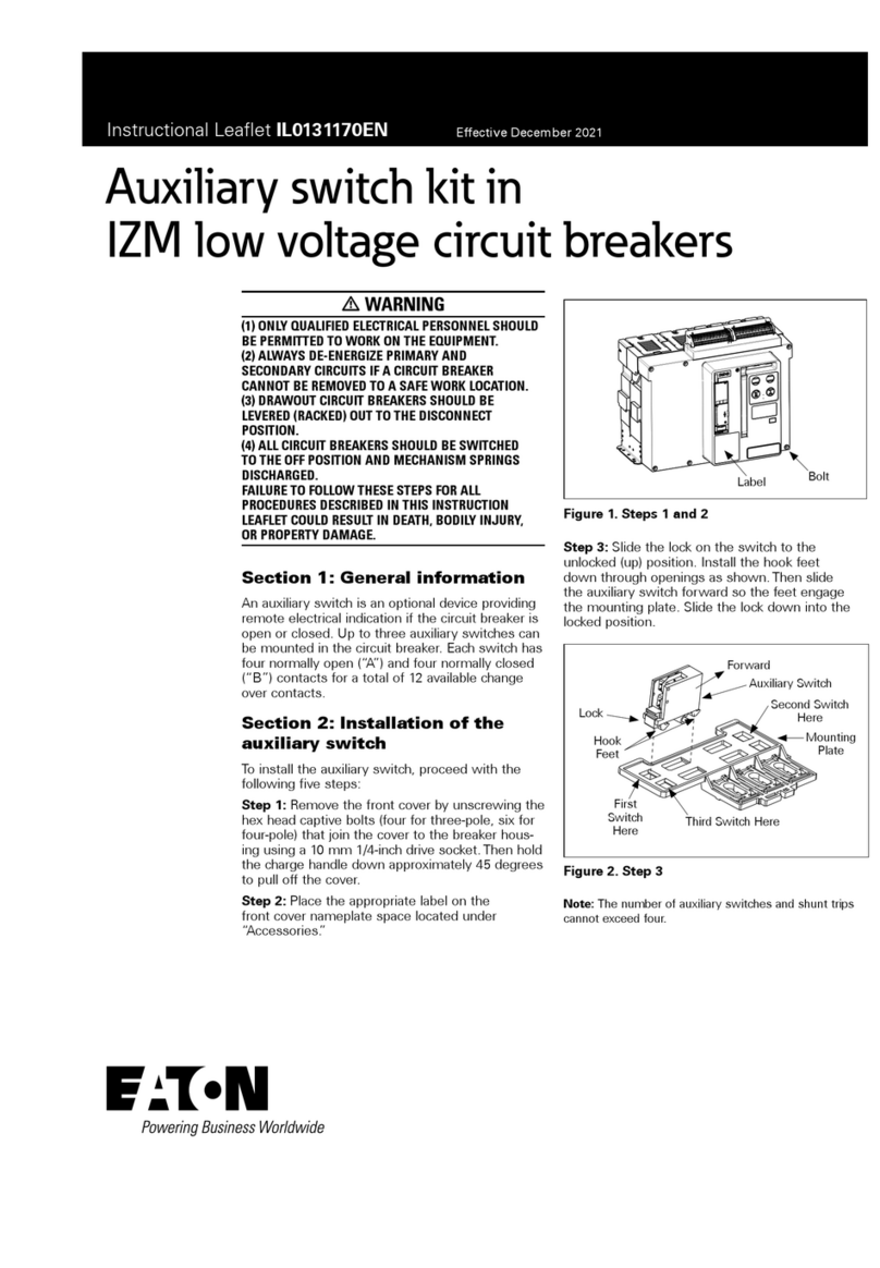
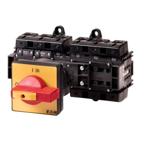
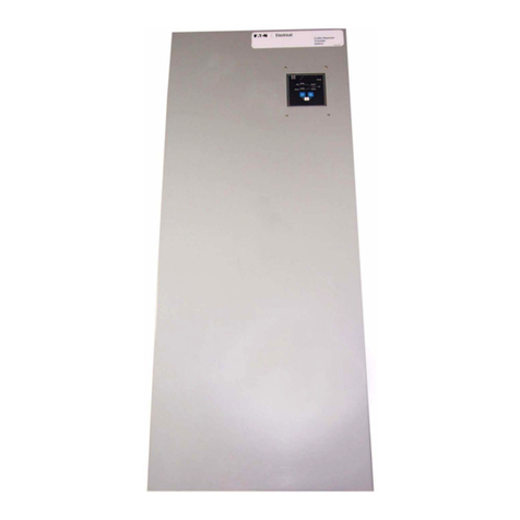
  9. Eaton Cutler-Hammer Programming manual

Eaton Cutler-Hammer Programming manual

THIS INSTRUCTION LEAFLET IS NOT A COMPLETE
SOURCE OF INFORMATION ON THE TRANSFER
EQUIPMENT. INSTALLATION SHOULD NOT BE
STARTED UNTIL THE ENTIRE INSTRUCTION BOOK
HAS BEEN REVIEWED AND UNDERSTOOD. FAIL-
URE TO FOLLOW INSTRUCTIONS CAN RESULT IN
DEATH, SEVERE PERSONAL INJURY OR PROPER-
TY DAMAGE.
Step 1: Mount the transfer switch on a flat rigid surface
(Figure 1). Shim if necessary. For seismic mounting
requirements, check the instruction book.
Non-Automatic Transfer Switch
Quick Start Instructions
Instruction Leaflet
Effective June 2003
IM01602002E For more information visit: www.cutler-hammer.eaton.com
!
WARNING
Figure 1 Mounting Details
Shim if Necessary
IM01602002E
For more information visit: www.cutler-hammer.eaton.com
Instruction Leaflet
Page 2Effective: June 2003
Non-Automatic
Transfer Switch
Quick Start Instructions
Figure 2 400A, 4 Pole, Non-Automatic Transfer Switch Interior
Step 2: Install power cables. Cables shall be sized and
installed per National Electrical Code, refer to NFPA70.
The cable must be sized within the specified cable size
range on the side of the cable connectors.
Connect cables and torque to correct value indicated on
the label near the lugs in the following order: [1] Load
Cables*(T1, T2, T3), [2] Source 1 or Utility Supply (N1,
N2, N3), [3] Source 2 or Generator Supply (E1, E2, E3).
For 4 pole transfer switches, connect load cables (T4),
Source 1 or utility supply (N4), and Source 2 or genera-
tor supply (E4). Refer to Figure 2for the location of all
parts discussed in this document.
*
Load cables on switches using the vertical design
MUST be connected and torqued BEFORE installing
the SUPPLY cables (Figures 3and 4).
Voltage Selector
Plug (Factory set at
600 VAC)
Optional Feature 37 Fuse
Disconnect Block
Transformer Panel
Option 41A, 100 Watt
Heater.
Note: Optional
Feature 41A, 100
Watt Heater Located
on Door
Feature 32A Timer
Source 1 Molded
Case Device
Source 1
Availability Relay
(Not for Customer
Use)
Motor Disconnect
KV Voltage Relay
Voltage Selection
Connectors
Source 2 (S2)
Power Terminals
Source 2 Molded
Case Device
Transfer
Mechanism
Indicator
Wheel
Manual
Operating
Handle
Source 1 (S1)
Power Terminals
Power
Panel
Load Lugs
(Top Entry)
Step 3: The Voltage Selector Plug is shipped in the
600Vac position. Move the Selector Plug to the appro-
priate position prior to energizing the switch. Make sure
the selector switch, on the Device Panel, is in the
“Source 1” position. Apply Utility (Source 1) Power. If
the switch is properly applied for the system voltage
selected, the
“Source 1” Available Light,
and
“Source 1”
Connected Light
should illuminate (Figure 5). Using a
voltmeter, check for proper system voltage on the nor-
mal and load terminals. Check all phases on a three-
phase switch. Voltage measurements should be taken
phase to phase and phase to neutral.
IM01602002E For more information visit: www.cutler-hammer.eaton.com
Instruction Leaflet
Page 3
Effective: June 2003
Non-Automatic
Transfer Switch
Quick Start Instructions
Figure 3 Vertical Power Panel Figure 4 Horizontal Power Panel
Figure 5 Non-Automatic Device Panel
The following lights must be ON:
● Source 1 Available
● Source 1 Connected
Step 4: Manually start the engine generator at the gen-
erator controller. Check that the
Source 2 Available
light is lit (Figure 6). Check all Voltages phase to phase
and phase to neutral.
Note: The transfer switch is equipped with a time
delay feature when in the Neutral position. This fea-
ture provides a delayed transition transfer mode for
an Open Transition Transfer Switch. Often used in
systems with inductive loads, a delayed transition
transfer switch may prevent or reduce excessive
inrush currents due to out of phase switching of
loads. This switch provides a time delay in the
Neutral position during the transfer and re-transfer
operations in which both Source 1 and Source 2 are
disconnected from the load circuit. The time delay
is adjustable and is the same for both transfer and
re-transfer operations. The range is from 3-60 sec-
onds.
Step 5: Move the Selector Switch, on the Device Panel,
to Source 2 (Figure 7). The Transfer Switch will move
to the Neutral Position, delay, and then move to the
Source 2 position. Check the
Source 1 Connected
light
and make sure it is extinguished. Check that the
Source 2 Connected
light is illuminated. Return the
Selector Switch to Source 1. Make sure the Transfer
Switch returns to
Source 1
and the
Source 1 Connected
light illuminates (Figure 6). Shut down the Generator
after the manufacturer’s recommended cool down time.
IM01602002E
For more information visit: www.cutler-hammer.eaton.com
Instruction Leaflet
Page 4Effective: June 2003
Non-Automatic
Transfer Switch
Quick Start Instructions
Figure 6 Utility Supplying Load and Generator Running Figure 7 Generator Supplying Load
The following lights should be ON:
● Source 1 Available
● Source 1 Connected
● Source 2 Available
The following lights should be ON:
● Source 1 Available
● Source 2 Available
● Source 2 Connected
This Transfer Switch may be equipped with a two posi-
tion Keyed Selector Switch that may be used as a
“Service Disconnect” (Figure 8) or as a “Disconnect”
(Figure 9). If this Transfer Switch does have the two
position Keyed Selector Switch, refer to IL01602002E
for proper labeling.
Operation of the Two Position Keyed Selector
Switch:
Operation 1: When the keyed Selector Switch is in the
“Energize” position, the Transfer Switch functions nor-
mally when the Source 1/Source 2 Selector Switch is
used (Figure 8and Figure 9).
Operation 2: To disconnect power from the Load: Turn
the Keyed Selector Switch to the “Disconnect” position
(Figure 10 and Figure 11), then remove the key. The
Transfer Switch will move to the neutral position and
remain there until the Keyed Selector Switch is returned
to the “Energized” position.
Operation 3: To reconnect power to the Load: Reinsert
the key and turn the Keyed Selector Switch to the
“Energize” position (Figure 8and Figure 9). The
Transfer Switch will move to the position indicated by
the Source 1/Source 2 Selector Switch.
IM01602002E For more information visit: www.cutler-hammer.eaton.com
Instruction Leaflet
Page 5
Effective: June 2003
Non-Automatic
Transfer Switch
Quick Start Instructions
Figure 10 Service Disconnect Disconnected Figure 11 Disconnect Disconnected
Figure 8 Service Disconnect Energized Figure 9 Disconnect Energized
Disconnected
Position Indicated
by Both Connected
Lights being
Extinguished
IM01602002E
For more information visit: www.cutler-hammer.eaton.com
Instruction Leaflet
Page 6Effective: June 2003
Non-Automatic
Transfer Switch
Quick Start Instructions
IM01602002E For more information visit: www.cutler-hammer.eaton.com
Instruction Leaflet
Page 7
Effective: June 2003
Non-Automatic
Transfer Switch
Quick Start Instructions
© 2003 Eaton Corporation
All Rights Reserved
Printed in USA
Publication No. IM01602002E (ISI)
June 2003
Eaton Corporation
Cutler-Hammer business unit
1000 Cherrington Parkway
Moon Township, PA 15108-4312
USA
tel: 1-800-525-2000
www.cutler-hammer.eaton.com
Instruction Leaflet
Page 8Effective: June 2003
Non-Automatic
Transfer Switch
Quick Start Instructions

Other manuals for Cutler-Hammer

2

Other Eaton Switch manuals

Eaton ATR Manual

Eaton

Eaton ATR Manual

Eaton MCS Series Manual

Eaton

Eaton MCS Series Manual

Eaton Cutler-Hammer J-Frame Series Guide

Eaton

Eaton Cutler-Hammer J-Frame Series Guide

Eaton RMQ-Titan M22 Series Manual

Eaton

Eaton RMQ-Titan M22 Series Manual

Eaton N2-4-S1-DC Series Manual

Eaton

Eaton N2-4-S1-DC Series Manual

Eaton Crouse-hinds series User manual

Eaton

Eaton Crouse-hinds series User manual

Eaton EATS30N User manual

Eaton

Eaton EATS30N User manual

Eaton ES Series User manual

Eaton

Eaton ES Series User manual

Eaton COOPER POWER LS4R Series User manual

Eaton

Eaton COOPER POWER LS4R Series User manual

Eaton Cutler-Hammer CHGENLC100ATS1SE User manual

Eaton

Eaton Cutler-Hammer CHGENLC100ATS1SE User manual

Eaton LCS Manual

Eaton

Eaton LCS Manual

Eaton P1-25-I2H-SW Manual

Eaton

Eaton P1-25-I2H-SW Manual

Eaton P3 V/SVB Series Manual

Eaton

Eaton P3 V/SVB Series Manual

Eaton Crouse-hinds series User manual

Eaton

Eaton Crouse-hinds series User manual

Eaton T0-4 SE2 Series Manual

Eaton

Eaton T0-4 SE2 Series Manual

Eaton NZM3-XMVR Manual

Eaton

Eaton NZM3-XMVR Manual

Eaton TRIPP LITE U360-004-IND User manual

Eaton

Eaton TRIPP LITE U360-004-IND User manual

Eaton AGswitch User manual

Eaton

Eaton AGswitch User manual

Eaton DILMP Series Manual

Eaton

Eaton DILMP Series Manual
Eaton ATC-900 User manual

Eaton

Eaton ATC-900 User manual

Eaton CI-PKZ0 Series Manual

Eaton

Eaton CI-PKZ0 Series Manual

Eaton Edison Cooper Power Series User manual

Eaton

Eaton Edison Cooper Power Series User manual

Eaton 9155 UPS User manual

Eaton

Eaton 9155 UPS User manual

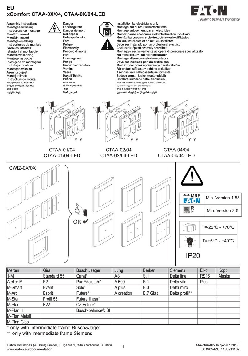
Eaton xComfort CTAA-02/04 User manual

Eaton

Eaton xComfort CTAA-02/04 User manual

Popular Switch manuals by other brands

Siemens NXPLUS C Installation and operating instructions

Siemens

Siemens NXPLUS C Installation and operating instructions

hager WXT30 Series manual

hager

hager WXT30 Series manual

H3C S9500 Series Command manual

H3C

H3C S9500 Series Command manual

FW Murphy VS2 installation instructions

FW Murphy

FW Murphy VS2 installation instructions

IOGear GUD3C04 quick start guide

IOGear

IOGear GUD3C04 quick start guide

ZIGBEE Enbrighten ZB4102 manual

ZIGBEE

ZIGBEE Enbrighten ZB4102 manual

Generac Power Systems OG 2697 Installation guidelines

Generac Power Systems

Generac Power Systems OG 2697 Installation guidelines

Draytek VigorSwitch P1282 quick start guide

Draytek

Draytek VigorSwitch P1282 quick start guide

SMC Networks ZSE40A(F) Operation manual

SMC Networks

SMC Networks ZSE40A(F) Operation manual

Melco S100 Quick setup guide

Melco

Melco S100 Quick setup guide

Microsoft MN-150 user guide

Microsoft

Microsoft MN-150 user guide

Cisco ME 3800X Command reference

Cisco

Cisco ME 3800X Command reference

ATEN ALTUSEN KH1508I Quick start quide

ATEN

ATEN ALTUSEN KH1508I Quick start quide

IDK MSD-402 user guide

IDK

IDK MSD-402 user guide

Vertiv Remote Access Key Quick installation guide

Vertiv

Vertiv Remote Access Key Quick installation guide

SWEEX US180 instructions

SWEEX

SWEEX US180 instructions

Alderon Industries SurfaceMax 8076 Operation, maintenance and installation manual

Alderon Industries

Alderon Industries SurfaceMax 8076 Operation, maintenance and installation manual

Buffalo BS-GU2008 user manual

Buffalo

Buffalo BS-GU2008 user manual

manuals.online logo
manuals.online logoBrands
  • About & Mission
  • Contact us
  • Privacy Policy
  • Terms and Conditions

Copyright 2025 Manuals.Online. All Rights Reserved.