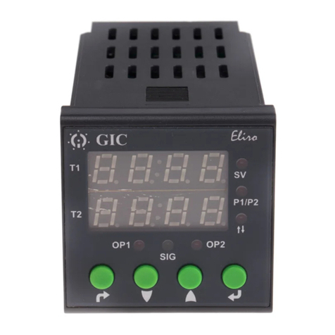
Eaton Durant Eclipse Series User manual

Durant®
Installation and Operation
Manual Number 57700-970-04
Durant
Eclipse Series Ratemeter/Process Timers
Models: 5770X-47X
Table of Contents
1 Introduction
1 Description
5 Mounting
6 Wiring
11 Programming
16 Diagnostics
19 Specifications
Visit our Web Site
at www.durant.com
Durant
®

1
This manual describes the installation of Durant clipse series digital ratemeter/
process timer models 5770X-47X. It begins with a description of the base unit and
the plug-in option boards. That is followed by mounting information, wiring diagrams,
and programming instructions. This manual concludes with diagnostic test and cali-
bration information and specifications. This device provides a rate or time readout
for the operator. Although the unit may be doing other functions as well, the only
thing the operator has to do with it is to observe the display.
DESCRIPTION
Base Unit
The clipse accepts a digital, pulsed signal from a sensor (that may be on an en-
coder, proximity or photo sensor, magnetic pickup, flowmeter, limit switch, etc.). It
calculates a rate or time, based upon the frequency of the input signal, to be dis-
played to the observer. The display can read in units of rate such as RPM, feet per
minute, barrels per hour, etc., or in units of time such as baking time or mold ma-
chine cycle time. In either case, the clipse employes the fiendishly clever Tau method
of calculation, which means that it very accurately times the period of the pulse
(Tau). Once Tau is known, the unit determines rate by the formula:
Rate = 1
Tau X Scaler
If the clipse is programmed to display process time, Tau is plugged into a slightly
different formula:
Process Time = Tau X Scaler
ither calculation requires that the installer program the unit with a scaler. The scaler
is a conversion factor that accounts for three conditions that are specific to the appli-
cation:
1. The units of time to be displayed, generally seconds, minutes, or hours.
2. The weight of each input pulse.
3. The resolution (decimal point location) of the display.
The installer calculates the scaler by using the appropriate formula below, depend-
ing upon whether the clipse should display rate or process time.
To display rate:
Scaler = NOS x DPF
PPI
,
where NOS = number of seconds in time unit (1 = seconds, 60 = minutes, 3600 =
hours, etc.).
INTRODUCTION / DESCRIPTION

2
DPF = decimal point factor. From the table below, select the DPF that matches the
display decimal point location:
Displayed Decimal Point D P F
XXXXX 1
XXXX.X 10
XXX.XX 100
XX.XXX 1000
X.XXXX 10000
And PPI = pulses per item, the number of pulses the unit receives from the sensor
per physical unit (revolution, foot, gallon, etc.) on the rate display.
To display process time:
Scaler = PPI x DPF
NOS
,
where NOS = number of seconds in the process time unit (1 = seconds, 60 = min-
utes, 3600 = hours, etc.).
DPF = decimal point factor, and is selected from the table above.
PPI = pulses per item, the number of pulses the unit receives from the sensor per
process cycle (oven length, mold machine cycle, etc.).
An inherent ability of devices that use the Tau method of calculation is that they can
calculate rate or process time and update the display each time an input pulse is
received. There is a practical limit to how fast the display should update, however,
especially when the process speed is changing and when there may be minor varia-
tions in pulse input frequency at a steady speed. The clipse has a programmable
display update time that sets the minimum time between updates. ach time the
display updates, the unit waits until the update timer times out and then updates the
display when the next pulse comes in. The clipse counts the number of pulses
received and times the total periods for all pulses received for each update. The
calculation averages Tau for all periods in the update effectively smoothing out the
display. The installer programs an update time in the range of 0.1 to 99.9 seconds to
obtain a display that is smooth, yet responsive.
Sooner or later, the process being monitored will be brought to a halt. Pulses will
stop coming in from the sensor. What happens once the update timer has timed out
and the clipse is patiently waiting for the next pulse to come in so that it can update
the display, but the next pulse is not coming? Like the bride who has been stood up
at the altar, something must tell the clipse that it is waiting in vain and it is time to
get on with its life. The clipse is equipped with a zero timer for this purpose. The
zero timer sets the units patience between pulses. The installer programs a zero
DESCRIPTION cont.
3
time in the range of 0.1 to 99.9 seconds. Should the time between pulses ever ex-
ceed the zero time, the clipse will immediately update the display to zero, whether
in rate or process time mode.
Relay Output Option Board
The optional relay board contains two form C (normally open and normally closed
contacts) relays. ach relay has an adjustable high and low setpoint. The relays act
as alarms by turning ON when the displayed rate or time is greater than the high
setpoint OR less than the low setpoint. If the low setpoint is greater than the high
setpoint, the relay turns ON when the rate or time meets both conditions; less than
the low setpoint AND greater than the high setpoint.
Once a relay turns ON, it stays ON until the rate or time returns back across the
setpoint and then some. The and then some is called hysteresis. Hysteresis is a
programmable value that is common to both setpoints and both relays. This means
that a relay turns OFF when the display is less than or equal to the high setpoint
minus the hysteresis value, or when the display is greater than or equal to the low
setpoint plus the hysteresis value. Should an overlap occur between ON and OFF
conditions, the ON condition overrides the OFF condition.
xample: Relay Output Operation
High Setpoint = 250 Relay ON above 250
Low Setpoint = 220 Relay ON below 220
Hysteresis = 10 Relay OFF between 230 and 240
OFF
ON ON
Displayed
Rate or
Time
OFF ONON
200 210 220 230 240 250 260
Analog Retransmission Option Board
The optional analog output board provides linear 0-10 V and 4-20 mA signals pro-
portional to the displayed rate or time. When the displayed value is equal to the
programmed output offset value, the output voltage is zero and the output current is
4 mA. When the displayed value is equal to the programmed output full scale value,
the output voltage is 10 V and the output current is 20 mA.
DESCRIPTION cont.
4
When the displayed value is between the output offset and output full scale value:
1. The output voltage = 10 (displayed rate - offset value)
(Full scale value - offset value)
V,
2. The output current = 16 (displayed rate - offset value)
(Full scale value - offset value) mA + 4 mA
RS 85 Serial Communications Option Board
The optional serial communication board allows a host device to download and read
programming parameters and to read status information from the rate meter, such
as display value, relay status, etc.
This manual does not contain information on the serial communication protocol or
the serial command list. That information is contained in the 57700 serial specifica-
tion and is obtainable by contacting the Durant Literature Department at 800-540-
9242 (U.S. and Canada), or 920-261-4070, or by FAX at 920-261-9097.
DESCRIPTION cont.
5
Mounting
Durant
®
3.31
3.63
.27
Mounting clips and screws shown in installed positions.
Mounting Instructions
1. Slide mounting gasket (not shown) over unit body until adhesive surface makes
contact with the front bezel.
2. Slide unit into cutout in panel.
3. Attach mounting clips and screws.
4. Tighten screws until unit is firmly in place. DO NOT OV RTIGHT N screws
to the point of squeezing the gasket out from behind the bezel.
MOUNTING
Panel Cutout
Max. Panel Thickness .190 [133.7]
[92.00]
[3.622 +/- .031]
[45.00]
1.772 +/- .024

6
WIRING
All wiring to the ratemeter is done via rear terminal, de-pluggable connectors. Up to
five headers accept the wired connectors on the ratemeter. All units have at least two
headers, power input and signal input. Any combination of three additional circuit
boards with headers may be installed. These option boards are relay output, RS 485
serial communications, and analog retransmission. The option boards occupy spe-
cific locations in the ratemeter and are not interchangeable.
Rear Terminal Layout
Relay
Output RS485
Communications Analog
Output DIP Switch
Signal Input
Power Input
2 Terminals for DC
Powered Units
3 Terminals for
AC Powered Units
Durant
®
111
11
WIRING

7
WIRING
Disconnect all power before wiring terminals. A safety hazard exists if this
precaution is not observed. Treat all signal inputs as hazardous since
they may carry line voltage.
A switch shall be included in the building installation:
It shall be in close proximity to the equipment and within easy reach of the
operator.
It shall be marked as the disconnecting device for the equipment.
Switches and circuit breakers in urope must comply with I C 947.
Terminal Connector Ratings
AC or DC Power Input / Relay Output: 10A, 250VAC;
Wire size: 12-24AWG (3.1mm2 - 0.24mm2), 600V.
RS485 / Analog Output / Signal Input: 8A, 125VAC;
Wire size: 16-28AWG (1.3mm2 - 0.1mm2), 300V.
General Wiring Practices
Use shielded cables for signal and control inputs.
Keep all signal lines as short as possible (<30M or 100 ft.).
Do NOT bundle or route signal lines with power or machine control wiring.
Do not allow signal or control wires to leave the building.

8
Wiring and DIP Switches
DC Power Input (for DC powered models 57700- 7X)
Durant
®
1
1
Power In
+
9-30 VDC
-
No Internal Fuse
1
{
External Fuse Size
U.S. European
2 AMP, 50 V
Time Delay T2A, 50 V
Time Delay
12 VA
AC Power Input (for AC powered models 57701- 7X)
No Internal Fuse
1
Power In L1
85-265 VAC L2
47-63 Hz
20 VA
Not
Used
1
Durant
®
1
{
External Fuse Size
U.S. European
0.2 AMP, 250 V
Time Delay T200mA, 250 V
Time Delay
WIRING

9
Signal Input
DIP Switch Position 1
12 VDC Out
1
2
3
4
+
ONDIP Switch Position 3 OFF
X
Rate Signal In
Program Enable In
Ground
Rate Input DIP Switch Settings
Position ON OFF
1
2
3
Sink (NPN)
200 Hz Max.
Mag Pickup
Source (PNP)
10 kHz Max.
Single Ended
12 VDC Out @ 75 mA Max.
See Specifications (pages 17-18) for input impedances and threshholds.
Relay Output Option Board
Typical Wiring
Durant
®
1
Terminal Designation
Relay
2
Relay
1
External
Power
6
5
4
3
2
1
Load
1
6
5
4
3
2
1
1
An RC surge suppressor is recommended across all inductive loads.
Contact Ratings
5 A @250 VAC or 30 VDC maximum
WIRING cont.

10
RS 85 Communication Option Board
Durant
®
1
485
+
485
-
Common
To Host Serial Port
Analog Output Option Board
Durant
®
4-20mA
+
1
0-10 V
+
Common
4-20mA
-
0-10 V
-
()
Output Ratings
4-20 mA into 750 W (Ohms) maximum
0-10 V into 2500 W (Ohms) minimum
WIRING cont.

11
Entering the Program Mode
Note: If the optional relay output and/or analog output board(s) are installed
in the ratemeter, entering the program mode will cause both relays to turn
OFF and the analog output to go to its minimum values (0V and 4 mA)
regardless of the input signal.
To enter the program mode:
1. Connect Program nable input terminal to Ground.
Durant
®
Jumper
Terminals
1 and 2
1
2
3
4
2. Press and hold the front panel program key (
PGM
); the display will say run:
Durant
PGM
3. Press the up or down arrow key ( or ) while holding (
PGM
); the
program L D will turn on and the display will show a parameter name.
Durant
®
PROGRAMMING
!

12
Programming Parameters
Programming customizes the ratemeters functions to fit the application. All pro-
gramming may be done by using the front panel program (
PGM
) and arrow keys - up
(), down ( ), and right ( ). Programming is done by entering the proper
value into each programming parameter. The parameters each have a name and a
value, and are shown in the parameter list starting on page 12. The programming
parameters associated with the optional RS 485 communications board, the analog
retransmission board, and the relay output board only show in the program list if the
corresponding option board is installed in the ratemeter.
To navigate through the parameter list, use the program key and the up and down
arrow keys.
1. The parameter name is displayed by pressing and holding the program key
(
PGM
).
2. The value of the parameter is displayed by releasing the program key.
3. While holding the program key (
PGM
), the unit scrolls down one parameter
name each time the down arrow ( ) key is pressed, and scrolls up one
parameter name each time the up arrow ( ) key is pressed. When the
PGM
key is released, the display shows the value of the selected parameter.
To change the value of the selected parameter:
1. Press the right arrow key ( ). For parameters that have selection lists
(such as display, decimal point, baud rate, etc.), the value will descent one
selection through the list each time the right arrow key is pressed. When the
desired value appears on the display, press
PGM
to go back to the parameter
name. For numeric values such as scaler, offset, full scale, setpoints, and
hysteresis; the most significant digit will flash.
Durant
®
PROGRAMMING cont.

13
PROGRAMMING cont.
2. Press to select which digit to change (flash), then use or to
change the value of the flashing digit.
Durant
®
3. After all digits have been edited, press
PGM
to go back to the parameter
name.
Durant
®
The Parameter List
The following list shows all programming parameter names, the default value for
each, and the selection range for each. A programmed unit may be restored to de-
fault settings by pressing both the program (
PGM
) and right arrow ( ) keys for
one second. The display will show dFL while the keys are pressed and blink off
momentarily when the default is done.
Parameter Default Description/
Name Value Range
Display rate or display process time.
Rate
Process time

14
PROGRAMMING cont.
Scaler decimal point. The scaler is in the
range of 0.001 to 9999 and is entered in
the parameter below. Set the decimal point
location for the scaler here.
Display decimal point location. This selection
nails the ratemeter or process time display
decimal point to a specific location and was
considered when the scaler was calculated.
No decimal point
Scaler. Enter the calculated scaler here. The de-
cimal point location on this screen was selected in
the scaler decimal point parameter above.
Range: 0.001 to 9999
Display update time. Sets the minimum time,
in seconds, between display updates.
Range: 0.1 to 99.9 seconds
Serial Address. Enter the serial address for the
ratemeter. All commands sent to the ratemeter
must contain this address. If two or more rate-
meters are connected in a network, each must
have a unique address.
Range: 00 to 99.
Display zero time. Sets the maximum time
that the unit will wait between pulses before
forcing the display to zero.
Range: 0.1 to 99.9 seconds

15
PROGRAMMING cont.
Parity. Select the type of parity used for
serial communications.
none
even
odd
Baud Rate. Select the rate in kBaud at which
to receive and transmit serial information.
Analog Output Offset Value. Enter the rate or
time that corresponds to the minimum analog
output (0V and 4 mA).
Range: 0 to 99999
Analog Output Full Scale Value. Enter the rate
or time that corresponds to the maximum analog
output (10V and 20 mA).
Range: 0 to 99999
Relay 1 High Alarm Setpoint. Enter the
rate or time
at which relay 1 will turn on if the rate or time goes
above this value.
Range: 0 to 99999.
Relay 2 High Alarm Setpoint. Enter the
rate or time
at which relay 2 will turn ON if the rate or time goes
above this value.
Range: 0 to 99999.
Relay 1 Low Alarm Setpoint. Enter the
rate or time
at which relay 1 will turn ON if the rate or time goes
below this value.
Range: 0 to 99999.
Relay 2 Low Alarm Setpoint. Enter the
rate or time
at which relay 2 will turn ON if the rate or time goes
below this value.
Range: 0 to 99999.

16
DIAGNOSTICS
Self Diagnostics and Error Messages
ach time power is applied to the ratemeter, it performs a series of internal diagnos-
tic tests. A lamp test (all display segments ON) is conducted while these tests are in
progress. If a failure occurs, an error message will appear on the display.
The diagnostic tests are checksum calculations of internal ROM and NOVRAM
memory and a read/write test for internal RAM. Programming and calibration data is
stored in NOVRAM (non-volatile RAM). The checksum test verifies that data stored
in NOVRAM at power down is still there, uncorrupted, at power up. The first tests are
performed on ROM and RAM. Failure results in an error message . This error is
non-recoverable, and the unit should be returned to the factory for repair. A failure in
the programming section of NOVRAM results in the displayed error message .
This message remains on the display until power to the ratemeter is cycled OFF,
then ON, or until a key is pressed. This error is recoverable by re-programming the
unit. If subsequent errors occur, the NOVRAM itself may have failed, and the
unit should be returned to the factory for repair. An error message indicates
that the calibration section of NOVRAM has been corrupted. THERE IS NO DIAG-
NOSTIC TEST TO DETERMINE THAT THE RATEMETER IS CALIBRATED! Turn
power to the unit OFF, and then ON. If appears on the display, return the unit to
the factory for repair. if the ratemeter powers up normally, the unit can be used only
after it has been calibrated.
Keyboard Diagnostic Mode
The keyboard diagnostics allows the user to test each of the front panel keys, the
display, and the analog retransmission and relay outputs if those optional boards are
installed.
Caution: performing the diagnostic tests will turn ON the analog transmis-
sion and relay outputs if those options are installed. Remove power from the
ratemeter and disconnect the outputs before entering the keyboard diagnos-
tic mode. If the optional RS 485 communication board is installed, the ratemeter will
respond with the rate or process time to the QST command.
PROGRAMMING cont. / DIAGNOSTICS
Relay Hysteresis. Enter the difference in
rate or time units between relay turn ON
values (setpoints) and relay turn OFF values.
Range: 0 to 999
!

17
DIAGNOSTICS cont.
To enter the keyboard diagnostic mode:
1. Turn power to the unit OFF.
Durant
®
1
Power
In
2
2. Connect the rear terminal program enable input to ground.
Durant
®
Jumper
Terminals
1 and 2
1
2
3
4
3. While holding both the right arrow key ( ) and the up arrow key ( ),
turn unit power ON.
Durant
Power
In
The program L D and all display segments will be ON. If present, both relays will be
OFF (coils de-energized) and the analog output will be at minimum value (4 mA and
0V).

18
There are four keyboard diagnostic tests, one for each key. The tests are performed
by pressing each key. The ratemeters response is maintained as long as the key is
held.
Test Key Unit Response
Program Display shows software part number.
Right Arrow All display segments and the program LED
turn off and the analog output goes to
maximum value (20 mA and 10V).
Up Arrow Each display digit will turn on, one at
a time, and relay 2 will turn on.
Down Arrow Each display segment of all displays
will turn on, one segment at a time,
and relay 1 will turn on.
To exit the diagnostic mode, turn unit power OFF.
DIAGNOSTICS cont.

19
MECHANICAL
Cutout Dimensions: 3.62 W x 1.77 H (92mm x 45mm) DIN standard
Outline Dimensions: 4.04 W x 2.19 H x 3.87 D (103mm x 56mm x 98mm)
3.60 (92mm) maximum depth in panel
nclosure: Plastic with polyester front label
Connectors: Up to five de-pluggable terminal blocks
INPUT POWER
AC Powered Models (57701-4XX)
Input Power: 85-265 VAC, 47-63 Hz, 20 VA
xternal Fuse: 0.2A, 250 VAC, Time Delay (T200mA, 250V)
Isolation Dielectric Strength: 2300 VAC
DC Powered Models (57700-4XX)
Input Power: 9-30 VDC, 12 VA
xternal Fuse: 2.0A, 50 VDC, Time Delay, (T2A, 50V)
Reverse Voltage Protection: Yes
Isolation Dielectric Strength: 2300 VAC to signal inputs and relays, 500 VAC to
RS 485 and analog outputs
HUMAN INTERFACE
Display: 5 digits
Type: .56 high, seven segment, red L D
Indicator: One red L D program/calibration indicator
Update Time: 0.1 to 99.9 seconds minimum
DATA RETENTION
Memory Type: PROM, no batteries required
Duration: 100 years
SIGNAL INPUT
Rate/Process Time: Signal In
Sensor Type: Sink or source, DIP switch selectable
Input Impedance: 4.75 k ohms to +5 VDC or 34.9 k Ohms to ground
Threshholds: High 3.5 to 28 VDC, low 0 to 1.9 VDC, for single
ended signals
Magnetic Pickup Range: 200 mV p-p to 65 VRMS into 34.9 k Ohms
Frequency Response: 200 Hz max. or 10 kHz max. (5 V signals), DIP
switch selectable
PROGRAM ENABLE INPUT
Sensor Type: Sink only
Input Impedance: 4.75 k Ohms to +5 VDC
SPECIFICATIONS
Other manuals for Durant Eclipse Series
3
This manual suits for next models
1
Table of contents
Other Eaton Timer manuals

Eaton
Eaton TSDW1COA-1 User manual

Eaton
Eaton easy500 Series Owner's manual

Eaton
Eaton TRL04 User manual

Eaton
Eaton AT2P Instruction manual

Eaton
Eaton TSSD1CO User manual

Eaton
Eaton 3h.508 User manual

Eaton
Eaton TSQW1CO User manual

Eaton
Eaton E5-248-C1420 User manual

Eaton
Eaton TRL04 Instruction manual

Eaton
Eaton AT18HM User manual