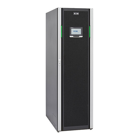
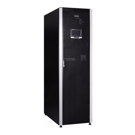
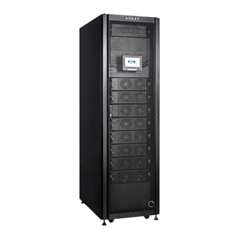
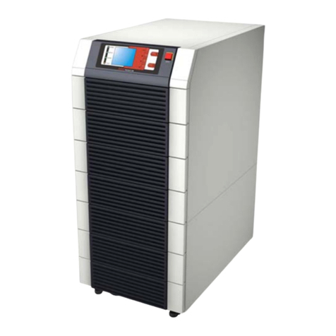
Eaton 9 55 Series User manual

p/n: 164000050
Revision 05
Eaton 9x55 UPS
Eaton 9390 UPS
Eaton 9395, 9395P, and 9395XC UPS
Eaton 93PM (480 ) and 93PM-L (208 ) UPS
Seismic Data Requirements for Eaton®® UPS Equipment Installation

Eaton reserves the right to change specifications without prior notice. Modbus is a registered trademark of Schneider Automation, Inc.
MOXA is a registered trademark and MGate is a trademark of MOXA, Inc. Spiralock is a registered trademark of Spiralock Corporation.
KIRK is a registered trademark of Kirk Key Interlock company, LLC, a subsidiary of Halma plc. National Electrical Code and NEC are
registered trademarks of National Fire Protection Association, Inc. ERIFLEX and FLEXIBAR are registered trademark of Erico International
Corporation. All other trademarks are property of their respective companies.
©Copyright 2011-2024 Eaton, Raleigh, NC, USA. All rights reserved. No part of this document may be reproduced in any way without the
express written approval of Eaton.

Seismic Data Requirements for Eaton UPS Equipment Installation User’s Guide 164000050—Rev 05 iii
TTaabbllee ooff CCoonntteennttss
11 IInnttrroodduuccttiioonn ttoo SSeeiissmmiicc MMoouunnttiinngg PPllaannss aanndd RReeqquuiirreemmeennttss..............................................................................................................................................................11
22 EEaattoonn 99xx5555 PPSS FFoouunnddaattiioonn PPllaann aanndd MMoouunnttiinngg RReeqquuiirreemmeennttss......................................................................................................................................................22
2.1 Displacement ............................................................................................................................................2
2.2 Center of Gravity ........................................................................................................................................3
2.3 Power Cables ............................................................................................................................................3
2.4 9x55 Floor Plan Sec ring Dimensions ............................................................................................................. 3
33 EEaattoonn 99339900 FFoouunnddaattiioonn PPllaann aanndd MMoouunnttiinngg RReeqquuiirreemmeennttss....................................................................................................................................................................66
3.1 Displacement ............................................................................................................................................6
3.2 Center of Gravity ........................................................................................................................................7
3.3 Power Cables ............................................................................................................................................7
3.4 9390 Floor Plan Sec ring Dimensions ............................................................................................................. 7
44 EEaattoonn 99339955,, 99339955PP aanndd 99339955XXCC FFoouunnddaattiioonn PPllaann aanndd MMoouunnttiinngg RReeqquuiirreemmeennttss ........................................................................................................ 1144
4.1 Displacement .......................................................................................................................................... 16
4.2 Center of Gravity ...................................................................................................................................... 17
4.3 Power Cables .......................................................................................................................................... 18
4.4 9395 Floor Plan Sec ring Dimensions ........................................................................................................... 18
55 EEaattoonn 9933PPMM ((448800VV)) aanndd 9933PPMM--LL ((220088VV)) FFoouunnddaattiioonn PPllaann aanndd MMoouunnttiinngg RReeqquuiirreemmeennttss ................................................................................ 2288
5.1 Displacement .......................................................................................................................................... 29
5.2 Center of Gravity ...................................................................................................................................... 30
5.3 Power Cables .......................................................................................................................................... 32
5.4 93PM Floor Plan Sec ring Dimensions .......................................................................................................... 32
5.5 Eaton 93PM-L UPS (208V) and 93PM UPS (480V) Seismic (OSHPD) Door Retention Kit Install Instr ctions.................. 50
5.5.1 Seismic Door Retention Kit Reference Images .......................................................................................... 51

iv Seismic Data Requirements for Eaton UPS Equipment Installation User’s Guide 164000050—Rev 05
LLiisstt ooff FFiigguurreess
Fig re 1. 9x55 Stackable Unit Seismic Mo nting Detail.......................................................................................4
Fig re 2. 9x55 20-30 kVA Cabinet Seismic Mo nting Detail ................................................................................. 5
Fig re 3. 9390 80 kVA UPS Seismic Mo nting Detail.......................................................................................... 8
Fig re 4. 9390 160 kVA UPS Seismic Mo nting Detail ........................................................................................ 9
Fig re 5. 9390 20-80 kVA IDC Seismic Mo nting Detail .................................................................................... 10
Fig re 6. 9390 20-80 kVA with Sidecar Seismic Mo nting Dimensions................................................................. 11
Fig re 7. 9390 100-160 kVA with Sidecar Seismic Mo nting Dimensions ............................................................. 11
Fig re 8. 9390 160 kVA IDC Seismic Mo nting Dimensions............................................................................... 12
Fig re 9. 9390 80 kVA and 160 kVA IAC (B, D, & T) .......................................................................................... 13
Fig re 10. 9395 275 kVA or 9395P 300/600 UPS Seismic Mo nting Dimensions...................................................... 18
Fig re 11. 9395 275 kVA or 9395P 300/600 kVA UPS and FI-UPM Seismic Mo nting Dimensions ............................... 18
Fig re 12. 9395 550 kVA or 9395P 600 kVA UPS Seismic Mo nting Dimensions ..................................................... 19
Fig re 13. 9395 550 kVA or 9395P 600 kVA UPS and FI-UPM Seismic Mo nting Dimensions..................................... 19
Fig re 14. 9395 825 kVA or 9395P 900 kVA UPS Seismic Mo nting Dimensions ..................................................... 20
Fig re 15. 9395 825 kVA UPS (2X-UPM) Seismic Mo nting Dimensions ................................................................ 20
Fig re 16. 9395 825 kVA or 9395P 900 kVA UPS (2X-UPM and FI-UPM) Seismic Mo nting Dimensions ....................... 20
Fig re 17. 9395 1100 kVA UPS or 825 kVA +1 or 9395P 1200 kVA UPS Seismic Mo nting Dimensions........................ 21
Fig re 18. 9395 MBM Seismic Mo nting Dimensions........................................................................................ 21
Fig re 19. 9395 MBM and 275 kVA UPS Seismic Mo nting Dimensions................................................................ 22
Fig re 20. 9395 MBM and 550 kVA UPS Seismic Mo nting Dimensions................................................................ 22
Fig re 21. 9395XC 1500 kW (HD) UPS Seismic Mo nting Dimensions .................................................................. 23
Fig re 22. 9395XC 1500 kW (LD) UPS Seismic Mo nting Dimensions................................................................... 23
Fig re 23. 9395 Seismic Door Sec ring Hardware Detail..................................................................................... 24
Fig re 24. 9395 I/O Intercabinet Shim Location and Seismic Floor Bracket Attachment Detail..................................... 25
Fig re 25. 9395 FI-UPM Shim Location Detail for Seismic Kit............................................................................... 26
Fig re 26. 9395 Attachment Detail for FI-UPM and I/O Mod le ............................................................................ 27
Fig re 27. 93PM-L UPS 60 and 120 kW (208V) /93PM UPS 50, 100, and 150 kW Frame (480V) Seismic Mo nting
Dimensions ................................................................................................................................ 33
Fig re 28. 93PM-L UPS 60 kW (208V) with Top Entry Sidecar /93PM UPS 50, 100, and 150 kW Frame (480V) with
Small Sidecar .............................................................................................................................. 34
Fig re 29. 93PM-L UPS 60 kW with and 120 kW (208V) with Large Sidecar ............................................................ 35
Fig re 30. 93PM UPS 100 kW and 150 kW Frames with Large Sidecar (480V)......................................................... 36
Fig re 31. 93PM-L UPS 160 kW (208V) Seismic Mo nting Dimensions.................................................................. 37
Fig re 32. 93PM-L UPS 200 kW (208V) Seismic Mo nting Dimensions.................................................................. 38
Fig re 33. 93PM UPS (200 kW Frame) Seismic Mo nting Dimensions (480V) ......................................................... 39
Fig re 34. 93PM UPS (200 kW Frame with Sidecar) Seismic Mo nting Dimensions (480V) ........................................ 40
Fig re 35. 93PM UPS (400 kW Frame) Seismic Mo nting Dimensions (480V) ......................................................... 41
Fig re 36. 93PM-L (208V) and 93PM (480V) IAC-D Seismic Mo nting Dimensions ................................................... 42
Fig re 37. 93PM (480V) IAC-T Seismic Mo nting Dimensions.............................................................................. 43
Fig re 38. 93PM-L (208V) IAC-B and 93PM (480) IAC-BD Seismic Mo nting Dimensions .......................................... 44
List of Figures

Seismic Data Requirements for Eaton UPS Equipment Installation User’s Guide 164000050—Rev 05 v
Fig re 39. 93PM-L (208V) and 93PM (480V) IAC-PD Seismic Mo nting Dimensions ................................................. 45
Fig re 40. 93PM IBC-S Seismic Mo nting Dimensions....................................................................................... 46
Fig re 41. 93PM IBC-L and IBC-LH Seismic Mo nting Dimensions ....................................................................... 47
Fig re 42. 93PM IBC-L and IBC-LH with Sidecar Seismic Mo nting Dimensions...................................................... 48
Fig re 43. 93PM IBC-LW and IBC-LHW Seismic Mo nting Dimensions ................................................................. 49
Fig re 44. Seismic Door Retention Kit Bracket Details........................................................................................ 51
Fig re 45. Seismic Door Bracket Install Location and Details ............................................................................... 52
Fig re 46. Seismic Cabinet Bracket Install Location ........................................................................................... 53
Fig re 47. Seismic Cabinet Bracket Install Details ............................................................................................. 54
List of Figures

vi Seismic Data Requirements for Eaton UPS Equipment Installation User’s Guide 164000050—Rev 05
LLiisstt ooff TTaabblleess
Table 1. 9x55 Unit and Fastener Req irements from Unit to Floor .........................................................................2
Table 2. 9x55 Unit Seismic Displacement Req irements .....................................................................................2
Table 3. 9x55 Unit Center of Gravity Specifications ............................................................................................ 3
Table 4. 9390 Unit and Fastener Req irements from Unit to Floor ......................................................................... 6
Table 5. 9390 Unit Seismic Displacement Req irements..................................................................................... 6
Table 6. 9390 Unit Center of Gravity Specifications ............................................................................................7
Table 7. 9395/P/XC Unit and Fastener Req irements from Unit to Floor................................................................ 14
Table 8. 9395/P/XC Unit Seismic Displacement Req irements ........................................................................... 16
Table 9. 9395/P/XC Unit Center of Gravity Specifications ................................................................................... 17
Table 10. 93PM Unit and Fastener Req irements from Unit to Floor...................................................................... 28
Table 11. 93PM Unit Seismic Displacement Req irements ................................................................................. 29
Table 12. 93PM Unit Center of Gravity Specifications ......................................................................................... 30
List of Tables

Seismic Data Requirements for Eaton UPS Equipment Installation User’s Guide 164000050—Rev 05 1
CChhaapptteerr 11 IInnttrroodduuccttiioonn ttoo SSeeiissmmiicc MMoouunnttiinngg PPllaannss aanndd RReeqquuiirreemmeennttss
Eaton eq ipment represented in the following sections were s bjected to seismic testing in accordance with
the 2006 or 2012 International B ilding Code (IBC) and the 2007 California B ilding Code (CBC). The res lts of
these tests exceeded the req irements as stated within the IBC, CBC, and OSHPD and demonstrated the
ability to f nction after the test. All installation g idelines covered in this doc ment as well as the instr ction
and operations literat re provided with the eq ipment m st be followed to ens re installation s itable for a
seismic application.
Certificates for vario s types of distrib tion and control eq ipment along with an application paper,
“Earthq ake Req irements and Seismic Capabilities for Eaton’s Electrical Distrib tion and Control Eq ipment”
can be fo nd at www.eaton.com/seismic.
The California State Office of Statewide Health Planning and Development (OSHPD) pre-approval for this
eq ipment can be fo nd at https://oshpd.ca.gov/FDD/Pre-Approval/SpecSeisCert-wTemplate.html.

2 Seismic Data Requirements for Eaton UPS Equipment Installation User’s Guide 164000050—Rev 05
CChhaapptteerr 22 EEaattoonn 99xx5555 PPSS FFoouunnddaattiioonn PPllaann aanndd MMoouunnttiinngg RReeqquuiirreemmeennttss
Proper mo nting of the eq ipment is the single most important factor in withstanding a seismic event. The
fo ndation m st be level and contin o s nder the entire assembly. The fo ndation m st be designed to
withstand the reaction loads imposed on it by the eq ipment d ring a seismic event. At a minim m, the
fo ndation m st be designed to accommodate the tensile strength of the hardware indicated in Table 1.
The anchoring system sho ld be p t in place prior to eq ipment installation to red ce effort associated with
anchoring. Welding to embedded steel members is acceptable provided the strength of the welds is
comparable to the mo nting bolts.
The ser is responsible for compliance with all local seismic codes.
NNOOTTEE Anchoring hardware is not provided with Eaton seismic mo nting kits beca se the type
of hardware is dependant on the fo ndation constr ction and composition.
Table 1. 9x55 Unit and Fastener Requirements from Unit to Floor
T pe Bolt T pe and Size Torque Quantit
8-15 k A UPS, 2 High
Class 8.8, M10 42 Nm
31 lb-ft.
12
8-15 k A UPS, 3 High 12
8-15 k A EBC, 2 and 3 High 12
20-30 k A UPS Cabinet 10
20-30 k A Options Cabinet 10
NOTE The torque value for each extension bracket connecting bolt is listed below:
• Class 8.8 M6 Bolt = 12 Nm [9 lb-ft.]
• Class 8.8 M8 Bolt = 27 Nm [20 lb-ft.]
22..11 DDiissppllaacceemmeenntt
The horizontal displacement of the top of the eq ipment is listed in Table 2. The horizontal displacements given
in the table are pl s/min s val es. The eq ipment m st be at the minim m distance listed in the table to avoid
contact with other stationary objects d ring a seismic event.
Table 2. 9x55 Unit Seismic Displacement Requirements
T pe Front to Back Side to Side
8-15 k A UPS, 2 High 112 mm 112 mm
8-15 k A UPS, 3 High 117 mm 117 mm
8-15 k A EBC, 2 and 3 High 153 mm 153 mm
20-30 k A UPS Cabinet 122 mm 122 mm
20-30 k A Options Cabinet 121 mm 121 mm
Eaton 9x55 UPS Foundation Plan and Mounting Requirements

Seismic Data Requirements for Eaton UPS Equipment Installation User’s Guide 164000050—Rev 05 3
Consideration m st be given to attachments (cond its, b s d ct, etc.) made to the top of the eq ipment.
Attachments m st have provisions to accommodate the displacement of the eq ipment indicated in Table 2.
Entry from the bottom of the eq ipment eliminates the need for accommodating this motion for attachments.
22..22 CCeenntteerr ooff GGrraavviittyy
For seismic calc lations, the center of gravity can be approximated sing the dimensions in Table 3 with
respect to the left side bracket's front mo nting hole (x,y,z origin). UPS center of gravity dimensions are with
batteries installed.
Table 3. 9x55 Unit Center of Gravit Specifications
T pe X (left to right) Y (front to rear) Z (bottom to top)
8-15 k A UPS, 2 High 81 mm 452 mm 406 mm
8-15 k A UPS, 3 High 81 mm 452 mm 610 mm
8-15 k A EBC, 2 and 3 High 81 mm 452 mm 406 mm, 2 High
610 mm, 3 High
20-30 k A UPS Cabinet 178 mm 475 mm 838 mm
20-30 k A Options Cabinet 178 mm 275 mm 838 mm
22..33 PPoowweerr CCaabblleess
It is recommended that power cables be lashed together at least every meter within the eq ipment. Refer to
the appropriate Eaton UPS instr ction and operation man al for other req irements related to sec ring power
cables.
22..44 99xx5555 FFlloooorr PPllaann SSeeccuurriinngg DDiimmeennssiioonnss
Fig re 1 and Fig re 2 detail the meas rements for attaching the 9x55 seismic brackets to the floor of the
b ilding. The drawings are for reference only and are not to scale. Dimension are in millimeters (inches).
Eaton 9x55 UPS Foundation Plan and Mounting Requirements

6 Seismic Data Requirements for Eaton UPS Equipment Installation User’s Guide 164000050—Rev 05
CChhaapptteerr 33 EEaattoonn 99339900 FFoouunnddaattiioonn PPllaann aanndd MMoouunnttiinngg RReeqquuiirreemmeennttss
Proper mo nting of the eq ipment is the single most important factor in withstanding a seismic event. The
fo ndation m st be level and contin o s nder the entire assembly. The fo ndation m st be designed to
withstand the reaction loads imposed on it by the eq ipment d ring a seismic event. At a minim m, the
fo ndation m st be designed to accommodate the tensile strength of the hardware indicated in Table 4.
The anchoring system sho ld be p t in place prior to eq ipment installation to red ce effort associated with
anchoring. Welding to embedded steel members is acceptable provided the strength of the welds is
comparable to the mo nting bolts.
The ser is responsible for compliance with all local seismic codes.
NNOOTTEE Anchoring hardware is not provided with Eaton seismic mo nting kits beca se the type
of hardware is dependant on the fo ndation constr ction and composition.
Table 4. 9390 Unit and Fastener Requirements from Unit to Floor
T pe Bolt T pe and Size Torque Quantit
20-80 k A UPS
Class 8.8, M10 42 Nm
31 lb-ft.
10
20-80 k A UPS w/sidecar 11
100-160 UPS k A 14
UPS 100-160 k A w/sidecar 15
20-80 k A IDC 14
100-160 k A IDC 16
IAC-B and IAC-T 10
IAC-D 10
NOTE The torque value for each bracket-to-cabinet connecting bolt is listed below:
• Class 8.8 M8 Bolt = 27 Nm [20 lb-ft.]
• Class 8.8 M10 Bolt = 42 Nm [31 lb-ft.]
• Class 8.8 M12 Bolt = 87 Nm [64 lb-ft.]
33..11 DDiissppllaacceemmeenntt
The horizontal displacement of the top of the eq ipment is listed in Table 5. The horizontal displacements given
in the table are pl s/min s val es. The eq ipment m st be at the minim m distance listed in the table to avoid
contact with other stationary objects d ring a seismic event.
Table 5. 9390 Unit Seismic Displacement Requirements
T pe Front to Back Side to Side
20-80 k A UPS 30 mm 30 mm
20-80 k A UPS w/sidecar 30 mm 30 mm
Eaton 9390 Foundation Plan and Mounting Requirements

Seismic Data Requirements for Eaton UPS Equipment Installation User’s Guide 164000050—Rev 05 7
Table 5. 9390 Unit Seismic Displacement Requirements (Continued)
T pe Front to Back Side to Side
100-160 UPS k A 48 mm 48 mm
UPS 100-160 k A w/sidecar 48 mm 48 mm
20-80 k A IDC 140 mm 140 mm
100-160 k A IDC 108 mm 108 mm
IAC-B and IAC-T 36 mm 36 mm
IAC-D 36 mm 36 mm
Consideration m st be given to attachments (cond its, b s d ct, etc.) made to the top of the eq ipment.
Attachments m st have provisions to accommodate the displacement of the eq ipment indicated in Table 5.
Entry from the bottom of the eq ipment eliminates the need for accommodating this motion for attachments.
33..22 CCeenntteerr ooff GGrraavviittyy
For seismic calc lations, the center of gravity can be approximated sing the dimensions in Table 6 with
respect to the left side bracket's front mo nting hole (x,y,z origin).
Table 6. 9390 Unit Center of Gravit Specifications
T pe X (left to right) Y (front to rear) Z (bottom to top)
20-80 k A UPS 252 mm 248 mm 940 mm
20-80 k A UPS w/sidecar 393 mm 248 mm 940 mm
100-160 UPS k A 482 mm 248 mm 965 mm
UPS 100-160 k A w/sidecar 540 mm 248 mm 965 mm
20-80 k A IDC 482 mm 248 mm 965 mm
100-160 k A IDC 575 mm 248 mm 965 mm
IAC-B and IAC-T 319 mm 248 mm 965 mm
IAC-D 319 mm 248 mm 965 mm
33..33 PPoowweerr CCaabblleess
It is recommended that power cables be lashed together at least every meter within the eq ipment. Refer to
the appropriate Eaton UPS instr ction and operation man al for other req irements related to sec ring power
cables.
33..44 99339900 FFlloooorr PPllaann SSeeccuurriinngg DDiimmeennssiioonnss
Fig re 3 thro gh Fig re 9 detail the meas rements for attaching the 9390 seismic brackets to the floor of the
b ilding. The drawings are for reference only and are not to scale. Dimension are in millimeters (inches).
Eaton 9390 Foundation Plan and Mounting Requirements

14 Seismic Data Requirements for Eaton UPS Equipment Installation User’s Guide 164000050—Rev 05
CChhaapptteerr 44 EEaattoonn 99339955,, 99339955PP aanndd 99339955XXCC FFoouunnddaattiioonn PPllaann aanndd MMoouunnttiinngg RReeqquuiirreemmeennttss
Proper mo nting of the eq ipment is the single most important factor in withstandi ng a seismic event. The
fo ndation m st be level and contin o s nder the entire assembly. The fo ndation m st be designed to
withstand the reaction loads imposed on it by the eq ipment d ring a seismic event. At a minim m, the
fo ndation m st be designed to accommodate the tensile strength of the hardware indicated in Table 7.
The anchoring system sho ld be p t in place prior to eq ipment installation to red ce effort associated with
anchoring. Welding to embedded steel members is acceptable provided the strength of the welds is
comparable to the mo nting bolts.
The ser is responsible for compliance with all local seismic codes.
NNOOTTEE Anchoring hardware is not provided with Eaton seismic mo nting kits beca se the type
of hardware is dependant on the fo ndation constr ction and composition.
Table 7. 9395/P/XC Unit and Fastener Requirements from Unit to Floor
Product T pe Bolt T pe and Size Torque Quantit
9395
275 k A UPS
Class 8.8, M12 83 Nm
61 lb-ft.
8
275 k A UPS and FI-UPM 12
550 k A UPS 8
550 k A UPS and FI-UPM 14
825 k A UPS 16
825 k A UPS (2X-UPM) 14
825 k A UPS (2X-UPM and FI-UPM) 20
1100 k A or 825 k A and FI-UPM 22
225-550 k A MBM 8
275 k A UPS and MBM 12
550 k A UPS and MBM 14
9395P
300 k A UPS
Class 8.8, M12 83 Nm
61 lb-ft.
8
300 k A UPS and FI-UPM 12
300 k A UPS (2X-UPM) 14
600 k A UPS 8
600 k A UPS and FI-UPM 14
600 k A UPS (2X-UPM) 12
600 k A UPS (FL-UPM and 2X-UPM) 12
900 k A UPS (FL-UPM and 2X-UPM) 14
900 k A UPS (FL-UPM and 3X-UPM) 14
900 k A UPS (2X-UPM) 14
Eaton 9395, 9395P and 9395XC Foundation Plan and Mounting Requirements
This manual suits for next models
6
Table of contents
Other Eaton UPS manuals

Eaton
Eaton 9EHD-33-40/20 Operating instructions

Eaton
Eaton 9PX3K3U User manual

Eaton
Eaton Powerware 9390 User manual

Eaton
Eaton 500 User manual

Eaton
Eaton Ferrups FX User manual

Eaton
Eaton 9PX 1000i User manual

Eaton
Eaton Powerware 3105 UPS User manual

Eaton
Eaton 9E 10000i User manual

Eaton
Eaton Power Xpert 9395C User manual

Eaton
Eaton 93E User manual

Eaton
Eaton 20000i User manual

Eaton
Eaton 9395 UPS User manual

Eaton
Eaton 1000L User manual

Eaton
Eaton Powerware 9135 User manual

Eaton
Eaton Powerware 9390 User manual

Eaton
Eaton Powerware 9140 User manual

Eaton
Eaton 9PHD Manual

Eaton
Eaton E Series DX User manual

Eaton
Eaton 93PM Series User manual

Eaton
Eaton Powerware 9390 User manual