EAW MKD Series User manual

MKD Series U-Bracket Instructions

____________________________________________________________________________________
Original Instructions
These instructions are for defining acceptable MKD800, MKD1000, or MKD1200 U-Bracket installations to
a mounting surface and for installing an MKD or MKD-WP Series Loudspeaker to an MKD Series U-Bracket.
IMPORTANT SAFETY INSTRUCTIONS –READ THIS FIRST
Safety Instructions
Read and heed all warnings and safety instructions in this manual before using this product. Failure to
follow these precautions may result in damage, injury, or death.
1) Read these instructions.
2) Keep these instructions.
3) Heed all warnings.
4) Follow all instructions.
5) Clean only with a dry cloth.
6) Install loudspeaker in accordance with the manufacturer's instructions.
7) Do not install near any heat sources such as radiators, heat registers, stoves, or other apparatus that
produce heat.
8) Only use attachments/accessories specified by the manufacturer.
9) Refer all servicing to qualified service personnel. Servicing is required when the apparatus has been
damaged in any way, does not operate normally, or has been dropped.
10) Use personal protective equipment not limited to gloves, safety goggles, ear protection, and lifting
supports.
Suspension Warnings
WARNING: Suspending anything, especially overhead of people, should be done with extreme caution.
Always engage the services of a certified professional who is qualified to determine the requirements for
and to implement overhead rigging. Only persons with the knowledge of proper hardware and safe rigging
techniques should attempt to suspend loudspeakers overhead. Failure to follow these precautions may
result in damage, injury, or death.

1. Inventory
Before beginning installation, inventory your available hardware to items listed.
Item
Description
Quantity
A
MKD Series U-Bracket
1
B
Button Head Screw, M10 X 45mm long
4
C
Flat Washer
4
D
Split-lock Washer
4
E
Rubber Washer, 3mm thick
2
F
Rubber Washer, 6mm thick
2
**Tools Needed: 6mm Allen wrench**

2. MKD Series U-Bracket limits of use
a. The MKD Series U-Brackets are designed to suspend each corresponding MKD Series
loudspeaker with a design factor of 10:1 to meet or exceed most global suspension
regulations. Below are the maximum working load limits of each MKD Series U-Bracket
at 10:1, 7:1 and 5:1 Design Factors.
Maximum Working Load Limit
Design Factor
10:1
7:1
5:1
MKD800 U-Bracket
67lb (298N)
95lb (425N)
134lb (596N)
MKD1000 U-Bracket
118lb (524N)
168lb (748N)
236lb (1049N)
MKD1200 U-Bracket
173lb (769N)
247lb (1098N)
346lb (1539N)
These values have been confirmed with Finite Element Analysis and destructive testing
b. The weight/mass of each MKD Series U-Bracket is listed below
MKD800 U-Bracket
5lb (2.3kg)
MKD1000 U-Bracket
8lb (3.6kg)
MKD1200 U-Bracket
15lb (6.8kg)
c. The MKD Series U-Brackets are designed to suspend only one loudspeaker per u-bracket.
d. Any geometric or structural modifications to the MKD Series U-Bracket or hardware are
not EAW-approved will void the warranty and may result in damage, injury, or death.
e. WARNING: Take care when lifting MKD Series products to avoid harm or damage to
product.
f. WARNING: MKD U-Brackets are for suspension of loudspeakers only. Suspension of
persons is prohibited.
3. Installation of the MKD Series U-Bracket to a mounting surface
a. Test fit an MKD Series U-Bracket on an MKD Series Loudspeaker to confirm the correct
angle, loudspeaker and u-bracket orientation before installing the U-bracket to the
mounting surface.
b. The MKD Series Loudspeaker may have weather-protected fiberglass shell which
increases the size of the loudspeaker. There are multiple sized rubber washers (E and F)
included with the MKD Series U-Bracket to accommodate
the larger loudspeaker size. Select the rubber washer to
best fill the gap between the loudspeaker and u-bracket
for use equally on both sides of the loudspeaker.
c. Configurations - Depending on mounting option used, the
MKD Series U-Bracket may be installed horizontal (back
and arms are level/parallel to the ground) or downward
(back and arms are plumb/perpendicular to the ground).
Any other configuration is not an EAW-approved
configuration and may result in damage, injury, or death.
Downward configuration

i. Note, the outermost mounting point “A” is
designed as an open slot to allow for easy
locating of an MKD Series Loudspeaker and
loosely pre-installed hardware. If using the
slotted mounting point, the MKD Series U-
Bracket must be installed oriented with the slot
angled upward, opposing the ground.
d. Level - The back channel of the MKD Series U-Bracket must be level when installed to the
mounting surface and before installing an MKD Series Loudspeaker to the U-Bracket.
e. Mounting options
NOTE: It is recommended that you consult a building professional for the proper mounting hardware
before mounting the bracket. Due to various construction methods and materials, the hardware for
securing the bracket to the mounting surface is not supplied. It is required that the use of hardware
locking methods, not limited to lock washers, thread-locker, or nylon-retention feature, be applied
when securing the u-bracket to the mounting surface or structure.
The MKD Series U-Bracket has three mounting options:
i. Four sets of slots for user supplied M6 or 1/4in hardware.
1. These slots are spaced to align for standard stud spacing and allow for
slight variations from standard stud spacing.
2. If installing the MKD Series U-Bracket by these slots, one slot in each of
the four sets must be secured, for a total of 4 slots secured (one slot
secured in each of the four quarters of the back channel).
3. When installing the MKD Series U-Bracket using the slots, the MKD Series
U-Bracket may be installed horizontal (back and arms are level/parallel to
the ground) or downward (back and arms are plumb/perpendicular to
the ground).
ii. Two outer Ø9/16in (Ø14.3mm) holes for user supplied M12 or 1/2in hardware.
1. These outer holes are spaced to align with holes in common structural
channel.
2. If installing the MKD Series U-Bracket by the outer holes, both holes must
be secured.
3. When installing the MKD Series U-Bracket using the outer holes, the MKD
Series U-Bracket may only be installed downward (back and arms are
plumb/perpendicular to the ground).
iii. Two inner Ø7/8in (Ø22.5mm) holes for user supplied hardware.
Horizontal configuration
i
ii
iii

1. These inner holes are spaced to align with the input section of an MKD
Series Loudspeaker. The two inner holes may be used as a wiring
passthrough in a non-structural, non-load-bearing manner with a 1/2in
(M16) conduit adapter.
2. The two inner holes may be used to structurally install the MKD Series U-
Bracket to a mounting surface using load bearing hardware; both holes
must be secured.
3. When structurally installing the MKD Series U-Bracket using the inner
holes, the MKD Series U-Bracket may only be installed downward (back
and arms are plumb/perpendicular to the ground).
4. Installation of an MKD Series Loudspeaker to the MKD Series U-Bracket.
a. Choosing an MKD Series Loudspeaker configuration
i. Each MKD Series U-Bracket has several MKD Series Loudspeaker mounting and
angle lock options.
ii. Mounting points are indicated below by a letter. The varying mounting points
offer different distance settings to the MKD Series Loudspeaker from the
mounting surface. The varying mounting points also offer different angle lock
settings. The selected mounting point is always connected to the MKD Series
Loudspeaker using the centermost M10 screw location on the top and bottom of
the MKD Series Loudspeaker.
1. Note, the outermost mounting point “A” is designed as an open slot to
allow for easy locating of an MKD Series Loudspeaker and loosely pre-
installed hardware. If using the slotted mounting point, the MKD Series
Rubber Washer (E/F)
A
B
Flat Washer (C)
Locking Washer (D)
Note: Locking washer is first on bolt, then flat washer

U-Bracket must be installed oriented with the slot angled upward,
opposing the ground.
iii. Angle lock points are indicated below by a number. Use of the angle lock points
is optional. The angle lock points are used for locking the MKD Series
Loudspeaker at a specific pre-determined angle.
1. If an Angle lock point is not used, the loudspeaker may secure the
loudspeaker at any angle by torqueing the mounting point hardware.
2. Note, there is an additional M10 screw in the bottom of each MKD Series
loudspeaker. This one location allows for additional angle lock settings
when using the MKD Series U-Bracket.
iv. The mounting points offer the following lock angles when used in conjunction
with the angle lock points. These angles are measured from perpendicular to the
mounting surface. For a wall-mount configuration, 0° is aiming directly away from
the mounting surface. For a ceiling-mount configuration, 0° is aiming directly
downward.
MKD800 Series U-Bracket Mounting and Angle Lock Points
MKD1000 Series U-Bracket Mounting and Angle Lock Points
A
B
A
B
1
C
2
2
3
1
2
2
3
3
4

MKD1200 Series U-Bracket Mounting and Angle Lock Points
Not Available with the WP Version
v. Test fit an MKD Series U-Bracket on an MKD Series Loudspeaker to confirm the
correct angle, loudspeaker and u-bracket orientation before installing the U-
bracket to the mounting surface.
b. Removing existing hardware
i. MKD Series U-Brackets are mounted to MKD Series Loudspeakers using a button
head screw located at the center of the top and bottom of each loudspeaker.
ii. Using a 6mm Allen wrench, remove the flat head screws located at the center of
the top and bottom of the MKD Series Loudspeaker.
iii. If choosing to use the MKD Series U-Bracket angle lock points, locate the flat head
screw in the loudspeaker that corresponds with the intended install angle. Using
Mounting
Point
Angle
Lock
Point
MKD800 U-Bracket
MKD1000 U-Bracket
MKD1200 U-Bracket
“A”
1
0°
0°
0°
2
+/-12°
+/-8°
+/-6°
3
+/-25°, +/-55°, +/-75°, +/-105°
+/-12°
4
+/-40°, +/-90°
+/-40°, +/-90°
5
+/-32.5°, +/-47.5°, +/-82.5°, +/-97.5°
6
+/-25°, +/-55°, +/-75°, +/-105°
“B”
1
+/-35°
+/-40°
+/-40°, +/-90°
2
+/-12.5°, +/-57.5°
+/-55°, +/-75°, +/-105°
+/-49°, +/-81°, +/-99°
3
0°
+/-22°, +/-58°, +/-72°, +/-108°
7
0°
8
+/-13.5°
“C”
3
+/-75°
8
+/-70°

a 6mm Allen wrench, remove the flat head screw from the threaded point that
will be used for locking the angle.
c. The MKD Series Loudspeaker may have weather-protected fiberglass shell which
increases the size of the loudspeaker. There are multiple sized rubber washers (E and F)
included with the MKD Series U-Bracket to accommodate the larger loudspeaker size.
Select the rubber washer to best fill the gap between the loudspeaker and u-bracket for
use equally on both sides of the loudspeaker.
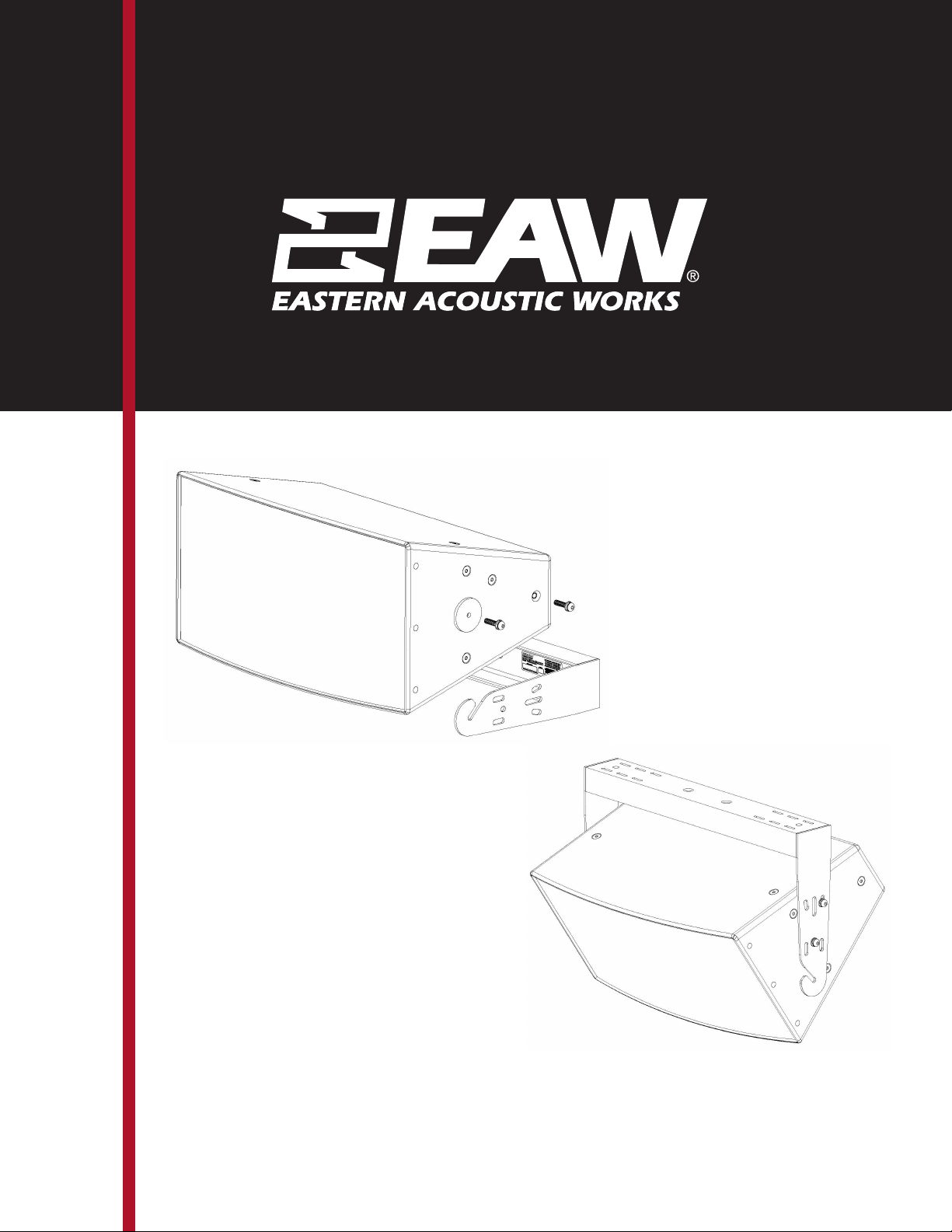
d. Installing the MKD Series Loudspeaker onto a mounted MKD Series U-Bracket.
i. WARNING: Take care when handling and wear PPE gloves to protect from
crushing and impacts with digits, limbs, and/or product.
ii. Note, for weather protected applications (using MKD-WP Series Loudspeakers),
apply user-supplied, waterproof, non-hardening, non-locking thread sealant to
the threads of two button head screws (B) per the thread sealant’s instructions.
Failure to do so could result in water ingress and damage to the loudspeaker.
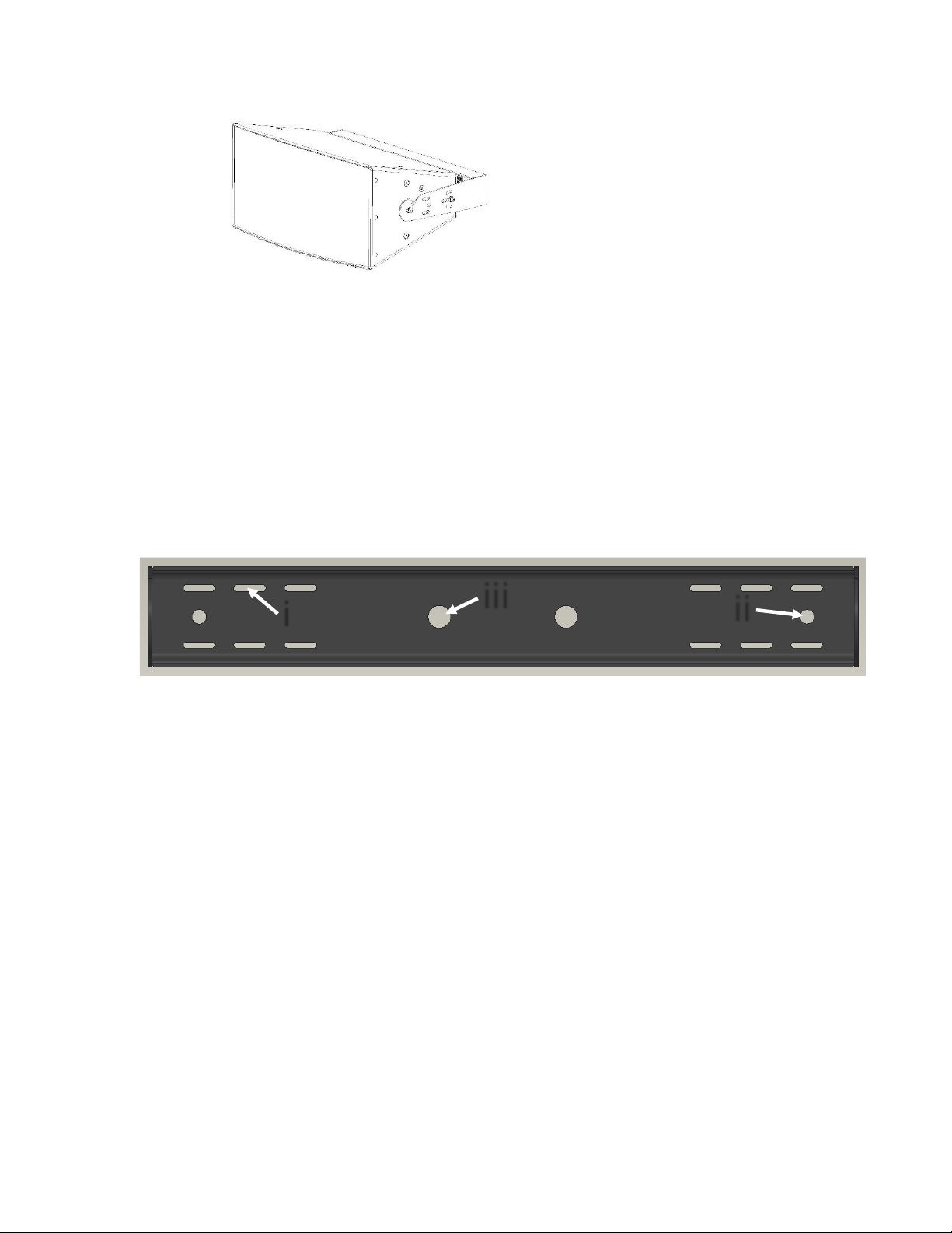
iii. Onto each of two button head screws (B), place a lock washer (C) and a flat
washer (D).
iv. WARNING HEAVY LIFTING, MULTIPLE PERSON LIFT –Lift the MKD Series
Loudspeaker to align the loudspeaker’s center threaded mounting hole with the
MKD Series U-Bracket preferred mounting point.
v. Using a 6mm Allen wrench, loosely thread the screws and washers (B, C & D)
through the MKD Series U-Bracket mounting point, through the selected rubber
washer (E or F) and into the loudspeaker’s center threaded mounting hole.
Repeat for the opposite side.
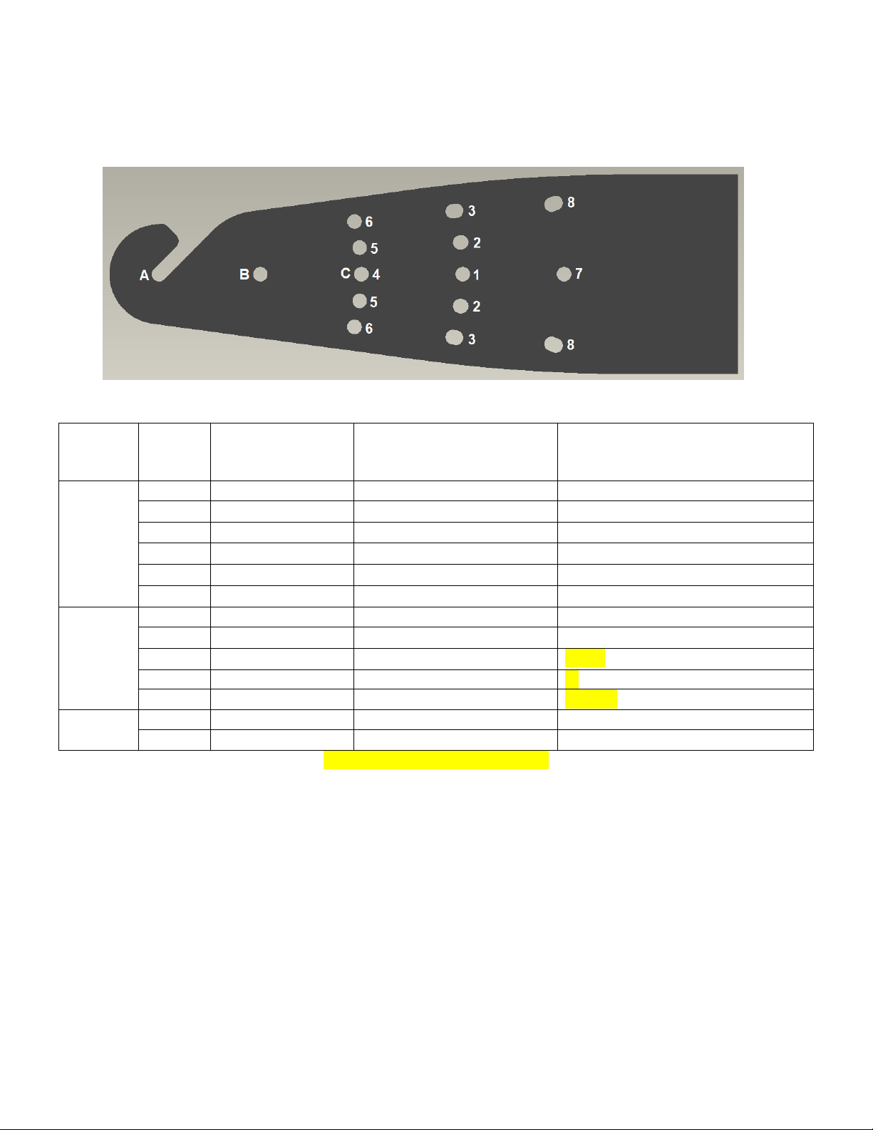
vi. If using the MKD Series U-bracket’s slotted mounting point “A”, the hardware
may be preassembled to the MKD Series Loudspeaker.
1. Note, if using the slotted mounting point, the MKD Series U-Bracket must
be installed oriented with the slot angled upward, opposing the ground.
2. Note, for weather protected applications (using MKD-WP Series
Loudspeakers), apply user-supplied, waterproof, non-hardening, non-
locking thread sealant to the threads of two button head screws (B) per
the thread sealant’s instructions. Failure to do so could result in water
ingress and damage to the loudspeaker.
3. Onto each of two button head screws (B), place a lock washer (C), a flat
washer (D) and the selected rubber washer (E or F). Thread these screws
and related hardware three complete turns into the loudspeaker’s two
center threaded mounting holes.
4. Leave as large a space as possible between the rubber washer (E or F) and
the flat washer (D).
5. WARNING HEAVY LIFTING, MULTIPLE PERSON LIFT –Lift the MKD Series
Loudspeaker into the MKD Series U-bracket slots with the large rubber
washers (E) inside the u-bracket and the flat and lock washers (C & D)
outside the u-bracket.
vii. Position the MKD Series Loudspeaker to the desired angle.

viii. If securing the angle using an angle locking point, align the empty threaded hole
to the preferred angle locking point.
1. Note, for weather protected applications (using MKD-WP Series
Loudspeakers), apply user-supplied, waterproof, non-hardening, non-
locking thread sealant to the threads of a button head screw (B) per the
thread sealant’s instructions. Failure to do so could result in water
ingress and damage to the loudspeaker.
2. Onto a button head screw (B), place a lock washer (C) and a flat washer
(D).
3. Using a 6mm Allen wrench, loosely thread the screw and washers (B, C &
D) through the MKD Series U-Bracket angle lock point and into the
loudspeaker’s center threaded mounting hole. Repeat for the opposite
side.
ix. Using a 6mm Allen wrench, tighten all button head screws (B).
5. Review the MKD Series Loudspeaker installation
a. Confirm the loudspeaker is level or plumb depending on the configuration.
b. Confirm the aim angle is as expected.
c. Confirm all hardware is tight.
d. For weather protected applications, confirm all sealants were applied properly.
6. Maintenance of an MKD Series U-Bracket installation
a. WARNING: Not following Maintenance instructions could result in equipment damage,
serious injury or death.
b. Maintenance should only be performed by an experienced technician.
c. As with any professional loudspeaker system, routine maintenance must be conducted in
order to ensure the longevity and safe, consistent performance.
d. Inspect the MKD Series U-Bracket for corrosion and other damage. U-brackets with
visible damage should be replaced and discarded.
e. Inspect hardware securing the u-bracket to the mounting surface for corrosion or
looseness. Tighten loose hardware and consider installing hardware locking methods.
Replace and discard corroded hardware.
f. Inspect hardware mounting the MKD Series loudspeaker to the u-bracket for corrosion or
looseness. Tighten loose hardware. Replace and discard corroded hardware.
g. For weather protected applications (using MKD-WP Series Loudspeakers), inspect
hardware sealants for cracking or gaps in sealant. Replace damaged sealant with user-
supplied, waterproof, non-hardening, non-locking sealant per the sealant’s instructions.
Failure to do so could result in water ingress and damage to the loudspeaker.
h. Clean the MKD Series U-Bracket and MKD Series Loudspeaker with a dry cloth.
7. Dismantling the MKD Series U-Bracket installation
a. WARNING HEAVY LIFTING, MULTIPLE PERSON LIFT –Fully support the weight of the MKD
Series Loudspeaker. Using a 6mm Allen wrench, remove the button head screws at the
mounting and angle lock points. Carefully lower the loudspeaker to the ground.

b. Support the weight of the MKD Series U-Bracket. Remove the mounting hardware
securing the u-bracket to the mounting surface. Carefully lower the u-bracket to the
ground.
c. Discard all damaged components.
EU Declaration of Conformity
EAW North America Inc hereby declares that this device is in compliance with Directive 2006/42/EC
A copy of this EU Declaration of Conformity is available at https://eaw.com/downloads/#142-660-wpfd-
certifications
Contacting EAW
We have attempted to make this manual and the instructions as thorough as possible. However, feel free
to contact us with any further questions or comments for topics not covered.
Operating Questions
EAW Applications Engineering & Support
Tel 508-234-6158 x3
Tel 800-992-5013 x3 (USA only)
E-mail [email protected]
Thank you for purchasing EAW products
EAW
One Main Street
Whitinsville, MA 01588
USA

©2020 Eastern Acoustic Works
All rights reserved. Products are not drawn to scale.
All terms, conditions, and specifications subject to change without notice.
RD3030 (C)
Eastern Acoustic Works
One Main Street
|
Whitinsville, MA 01588
|
USA
tel 800 992 5013 / +1 508 234 6158
www.eaw.com
This manual suits for next models
3
Other EAW TV Mount manuals