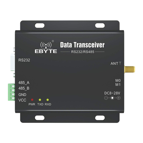
Ebyte E95-DTU 433C 485-V2 Series User manual

E95-DTU(433Cxx-485)-V2.0

Chengdu Ebyte Electronic Technology Co.,Ltd. E95-DTU(433Cxx-485)-V2.0 User manual
Copyright ©2012–2023,Chengdu Ebyte Electronic Technology Co.,Ltd. 2
Catalogs
Disclaimer and Copyright Notice..........................................................................................................................3
Ⅰ Product Overview..................................................................................................................................................4
1.1 Product Description..................................................................................................................................4
1.2 Features........................................................................................................................................................ 4
1.3 Quick Start ................................................................................................................................................5
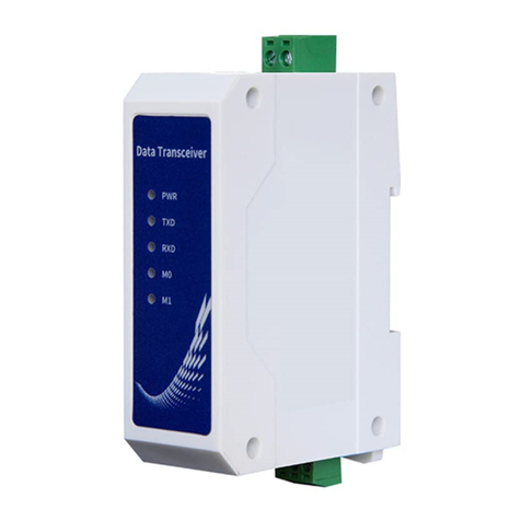
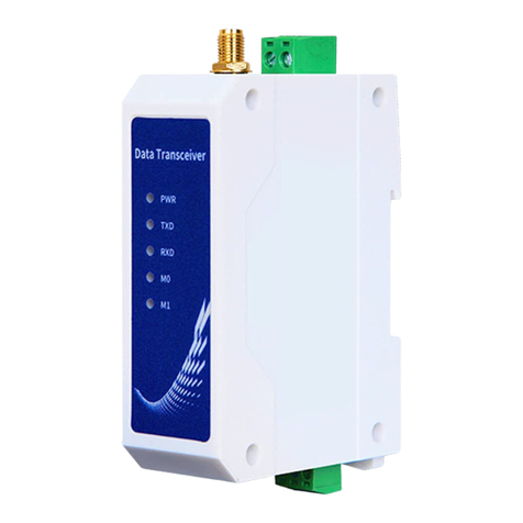
1.4 Description of each part........................................................................................................................7
1.5 Mounting Dimensions..................................................................................................................................8
Ⅱ Interface definition..........................................................................................................................................9
2.1 Power connector description..................................................................................................................9
2.2 Communication Interface Description................................................................................................. 9
Ⅲ Technical indicators........................................................................................................................................10
3.1 Model Specification ................................................................................................................................10
3.2 General Specification Parameters ..................................................................................................... 10
3.3 Frequency range and number of channels......................................................................................... 11
3.4 Transmit power level ..............................................................................................................................11
3.5 Airspeed rating........................................................................................................................................11
3.6 Current parameter ..................................................................................................................................11
3.7 Length of delivery and receipt and subcontracting modalities.............................................12
Ⅳ Operating mode ....................................................................................................................................................13
4.1 Continuous transmission mode (mode 0) ............................................................................................ 13
4.2 General transmission mode (mode 1)................................................................................................. 14
4.3 User configuration mode (mode 2)..................................................................................................... 15
4.4 Reserved mode (mode 3) ..........................................................................................................................15
Ⅴ Register read/write control..........................................................................................................................15
5.1 Command format..........................................................................................................................................15
5.2 Register description..............................................................................................................................16
5.3 Factory Default Parameters..................................................................................................................19
Ⅵ Relay Networking Mode Usage..........................................................................................................................20
Ⅶ Programming of radio station........................................................................................................................22
7.1 Schematic ....................................................................................................................................................22
7.2 Configuration Software Details......................................................................................................... 23
7.3 Firmware Upgrade.......................................................................................................................................24
Ⅷ Connection diagrams for testing and practical applications........................................................... 25
Ⅸ Practical application areas..........................................................................................................................25
Ⅹ Precautions of use ............................................................................................................................................26
XI Important statement..........................................................................................................................................27
Revision history......................................................................................................................................................27
About us ...................................................................................................................................................................... 28

Chengdu Ebyte Electronic Technology Co.,Ltd. E95-DTU(433Cxx-485)-V2.0 User manual
Copyright ©2012–2023,Chengdu Ebyte Electronic Technology Co.,Ltd. 3
Disclaimer and Copyright Notice
The information in this document, including the URL addresses for reference, is
subject to change without notice. this document is provided "as is" without warranty
of any kind, including any warranty of merchantability, fitness for a particular
purpose, or non-infringement, and any warranty that any proposal, specification, or
sample is referred to elsewhere. this document disclaims all liability, including
liability for infringement of any patent, arising out of the use of the information
in this document. This document does not grant any license, express or implied, by
estoppel or otherwise, to use any intellectual property.
The test data in this document are from tests conducted in the laboratory of
EVERBUILT, and the actual results may vary slightly.
All trade names, trademarks and registered trademarks mentioned herein are the
property of their respective owners and are hereby acknowledged.
The final explanation right belongs to Chengdu Ebyte Electronic Technology
Co.,Ltd.
Note: The contents of this manual are subject to change due to product version upgrade or other reasons. Chengdu
Ebyte Electronic Technology Co.,Ltd. reserves the right to make changes to the contents of this manual without
notice or prompting. Ltd. makes every effort to provide accurate information in this manual, however, Ebyte does
not warrant that the contents of this manual are error-free, and all statements, information and recommendations
in this manual do not constitute any warranty, express or implied.

Chengdu Ebyte Electronic Technology Co.,Ltd. E95-DTU(433Cxx-485)-V2.0 User manual
Copyright ©2012–2023,Chengdu Ebyte Electronic Technology Co.,Ltd. 4
Ⅰ Product Overview
1.1 Product Description
E95-DTU(433Cxx-485)-V2.0 is a continuous transmission type 433M wireless digital transmission module,
built-in high-performance microcontroller and wireless transceiver chip, working in 410 to 441MHz band (default
433MHz), transmitting power 20/30dBm. It works in 410-441MHz frequency band (default 433MHz), with 20/30dBm
transmit power, the main function is that when the module is in continuous transmission mode, it can perform
continuous uninterrupted transmission under different serial port baud rates, and the data output delay at the
receiving end is low, which is suitable for the need of rapid transmission of large data volume scenarios.
Wireless digital transmission radio as a communication medium, and optical fiber, microwave, open-wire, has
a certain scope of application: it provides some special conditions in the dedicated network of real-time monitoring
signals, reliable data transmission, has a low cost, easy installation and maintenance, strong ability to bypass
the shot, the network structure is flexible, the coverage range of the characteristics of the long distance,
suitable for the point of much more dispersed, geographically complex and other occasions, can be combined with
PLC, RTU, rain gauge, liquid level meter, etc., and can be used to transmit the data to and from the network.
It can be connected with PLC, RTU, rain gauge, liquid level meter and other data terminals.
1.2 Features
★General mode to support automatic relay networking, multi-level relay for ultra-long-distance communication,
the same area to run multiple networks running at the same time;
★Simple and efficient power supply design, support for power supply setter or pressure line mode, support for
8 to 28V power supply;
★Temperature compensation circuitry, frequency stability better than ±1.5PPM;
★Full aluminum alloy shell, compact size, easy to install, good heat dissipation;
★Power reverse connection protection, over connection protection, antenna surge protection and other multiple
protection functions, greatly increasing the reliability of the radio;
★Powerful software functions, all parameters can be set by programming: such as power, frequency, air rate,
address ID, etc.;
★Ultra-low power consumption, 12V power supply watchdog current is only 16mA;
★Built-in watchdog, and precise time layout, once an exception occurs, the radio will automatically restart,
and can continue to continue to work in accordance with the previous parameter settings;
★Support 0.5k~470kbps data transmission rate;
★E95-DTU (433C30-485)-V2.0 has built-in PA+LNA+SAW, and the communication distance can reach 10km under ideal
conditions;
★E95-DTU (433C20-485)-V2.0built-in LNA+SAW, communication distance up to 6km under ideal condition;
★Support RSSI signal strength indication function for assessing signal quality, improving communication network
and ranging;

Chengdu Ebyte Electronic Technology Co.,Ltd. E95-DTU(433Cxx-485)-V2.0 User manual
Copyright ©2012–2023,Chengdu Ebyte Electronic Technology Co.,Ltd. 5
★Support users to set their own communication key, and can not be read, greatly improving the confidentiality
of user data;
★Parameters are saved after power down, and the radio will work according to the set parameters after power
up again;
★Operating temperature range: -40 ° C ~ +85 ° C, to adapt to a variety of harsh operating environments, true
industrial-grade products;
1.3 Quick Start
1You need to prepare two E95-DTU(433Cxx-485)-V2.0
2First install the antenna to the digital radio, then install the power supply, and the user uses the
power adapter to supply power
3Use USB to RS485/RS232 or other means to connect the computer to the digital radio;

Chengdu Ebyte Electronic Technology Co.,Ltd. E95-DTU(433Cxx-485)-V2.0 User manual
Copyright ©2012–2023,Chengdu Ebyte Electronic Technology Co.,Ltd. 6
4Start two serial port debugging assistants, select the serial port baud rate of 9600bps (default), the
parity mode is 8N1, you can realize the serial port transmitting.;
If the customer needs to switch the working mode, it can be controlled by Mode button to switch different
working modes (M0 indicator, M1 indicator). Long press the Mode button once for 1ms and then release it to
switch the mode once, the details of mode switching are shown in the following table.
Mode
Type
M1
M0
Notes
Remarks
Mode 0
Continuo
us mode
Lights
out.
Lights
out.
The radio will automatically calculate
the required over-the-air transmission
rate for continuous uninterrupted
transmission according to the
user-configured serial port baud rate
internally, and the user can just pass
in the data uninterruptedly.
Supports continuous
uninterrupted transmission
Mode 1
General
mode
Lights
out.
lights
on
The radio internally enforces the
user-configured over-the-air
transmission rate. It will transmit in
packets at 55 bytes per packet.
General Transparent
Transmission
Mode 2
Configur
ation
Mode
lights
on
Lights
out.
The user can access the registers
through the serial port to control the
working status of the radio.
Requires configuration at
baud rate 9600
Mode 3
reserved
mode
lights
on
lights
on
The radio will not do any transmitting
or receiving in this mode.
Note: The radio has the function of power-down saving mode (factory default setting is transmissive mode),
users need to switch the corresponding mode according to M1, M0 indicator (effective immediately).

Chengdu Ebyte Electronic Technology Co.,Ltd. E95-DTU(433Cxx-485)-V2.0 User manual
Copyright ©2012–2023,Chengdu Ebyte Electronic Technology Co.,Ltd. 7
1.4 Description of each part
serial
number
Name
Function
Instruction
1
Mode
Mode switching
button
Operating mode switching control
2
ANT
RF interface
SMA-K, Male Female Bore
3
DC
Power connector
DC Power Input Port, Crimp Style Port
4
RS485
RS485
communication port
Standard RS485 interface
5
PWR
Power indicator
Lights up when power is turned on
6
TXD
Send Indicator
Blinking when sending data
7
RXD
Receiving
indicator
Blinking when receiving data
8
MO
Mode Indicator
Operating Mode Indicator
9
M1
Mode Indicator
Operating Mode Indicator

Chengdu Ebyte Electronic Technology Co.,Ltd. E95-DTU(433Cxx-485)-V2.0 User manual
Copyright ©2012–2023,Chengdu Ebyte Electronic Technology Co.,Ltd. 8
1.5 Mounting Dimensions

Chengdu Ebyte Electronic Technology Co.,Ltd. E95-DTU(433Cxx-485)-V2.0 User manual
Copyright ©2012–2023,Chengdu Ebyte Electronic Technology Co.,Ltd. 9
Ⅱ Interface definition
2.1 Power connector description
The E95-DTU(433Cxx-485)-V2.0 can be powered by an 8 to 28V (DC) power supply, and the wiring port is connected
using a terminal block (2 Pin).
2.2 Communication Interface Description
The E95-DTU(433Cxx-485)-V2.0 can be connected to the device via RS485 using the terminal block.
serial
number
Standard
Definition
Funcion
Instruction
1
G
signal ground
Anti-interference, Grounding
2
A
RS485 bus A interface
RS485 interface A interface connected to device
A interface
3
B
RS485 bus B interface
RS485 interface B interface to device B interface
★Note: Poor communication occurs when connecting the radio to multiple devices, but not when a single device

Chengdu Ebyte Electronic Technology Co.,Ltd. E95-DTU(433Cxx-485)-V2.0 User manual
Copyright ©2012–2023,Chengdu Ebyte Electronic Technology Co.,Ltd. 10
is connected, try connecting a 120Ω resistor in parallel between the 485_A terminal and the 485_B terminal.
Ⅲ Technical indicators
3.1 Model Specification
Model Specification
Frequency
Transmit
ting
power
Referenc
e
distance
Specification
Characteristi
cs
Recommended Scenarios
Hz
dBm
km
E95-DTU(433C20-485)-V2.0
410M-441M
20
1
High-speed
continuous
transmission
Suitable for data-heavy
applications and supports the
customer's Moudbus protocol.
20
6
General
Transfer Mode
Suitable for small data volume,
long distance application
environment.
E95-DTU(433C30-485)-V2.0
410M-441M
30
2
High-speed
continuous
transmission
Suitable for data-heavy
applications and supports the
customer's Moudbus protocol.
30
10
General
Transfer Mode
Suitable for small data volume,
long distance application
environment.
★Note: Sunny weather, open environment without shade, 12V/1A power supply, 5dBi suction cup antenna, antenna
height of 2 meters from the ground, use factory default parameters.
3.2 General Specification Parameters
Serial number
Item
Specification
Instruction
1
Product Size
92*66*30 mm
See mounting dimensions for details
2
Product weight
95 g
Weight tolerance 5g
3
Operating
temperature
-40℃~+85℃
Industrial grade
4
Voltage range
8~28V(DC)
12V or 24V recommended
7
Communication
interface
RS485
3.81 Terminal block
8
Baud rate
Factory default 9600
Baud rate range 2400 ~ 230400
9
Address code
Factory default 0
Total 65536 address codes can be set

Chengdu Ebyte Electronic Technology Co.,Ltd. E95-DTU(433Cxx-485)-V2.0 User manual
Copyright ©2012–2023,Chengdu Ebyte Electronic Technology Co.,Ltd. 11
3.3 Frequency range and number of channels
Model Specification
Default
frequency
Frequency range
Channel
spacing
Channel count
Hz
Hz
Hz
E95-DTU(433C20-485)-V2.0
433M
410~441M
500K
256,half-duplex
E95-DTU(433C30-485)-V2.0
433M
410~441M
500K
256,half-duplex
★Note: When using multiple sets of digital transmission radios in the same area to communicate one-to-one at
the same time, it is recommended that each set of digital transmission radios set a channel interval of 2MHz
or more.
3.4 Transmit power level
Model Specification
Factory Default
Grade
E95-DTU(433C20-485)-V2.0
20dBm
17dBm
14dBm
11dBm
E95-DTU(433C30-485)-V2.0
30dBm
27dBm
24dBm
21dBm
★Note: The lower the transmit power, the closer the transmission distance, but the operating current will not
be reduced in the same proportion, it is recommended to use the maximum transmit power.
3.5 Airspeed rating
Model Specification
Default Air
Rate
Level
Airspeed rating
bps
bps
E95-DTU(433C20-485)-V2.0
0.5k
17
0.5K、1.5k、3.5k、5.5k、6.5k、11k、13k、21k、
26k、42k、51k、82k、76k、125k、160k、410k、
470k
E95-DTU(433C30-485)-V2.0
★Note: The higher the air rate setting, the faster the transmission rate and the closer the transmission distance;
therefore, if the rate meets the usage requirements, it is recommended that the air rate be as low as possible.
3.6 Current parameter
Model Specification
Emitting current mA
Watching the currentmA
12V
24V
12V
24V
E95-DTU(433C20-485)-V2.0
`38
20
16
7.5

Chengdu Ebyte Electronic Technology Co.,Ltd. E95-DTU(433Cxx-485)-V2.0 User manual
Copyright ©2012–2023,Chengdu Ebyte Electronic Technology Co.,Ltd. 12
E95-DTU(433C30-485)-V2.0
350
150
16
7.5
★Note: It is recommended to keep more than 50% current margin when selecting the power supply, which is conducive
to the long-term and stable operation of the radio.
3.7 Length of delivery and receipt and subcontracting modalities
Model Specification
Cache size
Subcontracting
E95-DTU(433C20-485)-V2.0
4096 bytes
Default packetization 55 bytes
E95-DTU(433C30-485)-V2.0
★Note: 1, the above sub-packet transmission situation of the radio is only available in the general transparent
transmission mode, and uninterrupted transmission in the continuous transmission mode;
2、If the data received by the radio is larger than the capacity of a single packet, the exceeding part
of the data will be automatically assigned to the second transmission until the transmission is completed;
3、The radio can not receive data larger than the cache capacity in a single transmission;

Chengdu Ebyte Electronic Technology Co.,Ltd. E95-DTU(433Cxx-485)-V2.0 User manual
Copyright ©2012–2023,Chengdu Ebyte Electronic Technology Co.,Ltd. 13
Ⅳ Operating mode
The E95-DTUs all have four operating modes. For normal communication, you need to configure the radio to the
pass-through mode (Mode 0) by pressing the key, and the radio is set to the pass-through mode (Mode 0) by default
when it is shipped from the factory.
Mode
Type
M1
M0
Notice
Remark
Mode 0
General
mode
Lights
out
Lights
out
The radio will automatically
calculate the required over-the-air
transmission rate for continuous
uninterrupted transmission
according to the user-configured
serial port baud rate internally,
and the user can just pass in the data
uninterruptedly.
Supports continuous uninterrupted
transmission.
Model
1
reserved
mode
Lights
out
lights
on
The radio internally enforces the
user-configured over-the-air
transmission rate. It will transmit
in packets at 55 bytes per packet.
General Transparent Transmission.
Mode2
command
mode
lights
on
Lights
out
The user can access the registers
through the serial port to control
the working status of the radio.
Requires configuration at baud rate
9600.
Mode3
sleep
mode
lights
on
lights
on
The radio will not do any
transmitting or receiving in this
mode.
4.1 Continuous transmission mode (mode 0)
Type
When M0 = 0 and M1 = 0, the module operates in mode 0
Tran
smit
ting
The air rate required for continuous transmission is automatically calculated based on the serial
port baud rate configured by the user;
The user can input data through the serial port and the module will initiate wireless
transmission.
Rece
ivin
g
In the non-transmitting state, data can be received normally.
In continuous transmission mode, the intuitive experience is that the user does not need to wait for
all the data to be packaged to transmit the data out, but the module starts transmitting from the first
frame of data until the completion of the data that the user needs to transmit. This saves the time of
data packing and packetizing and greatly reduces the data delay
time.

Chengdu Ebyte Electronic Technology Co.,Ltd. E95-DTU(433Cxx-485)-V2.0 User manual
Copyright ©2012–2023,Chengdu Ebyte Electronic Technology Co.,Ltd. 14
Data delay schematic (at a serial port baud rate of 115200, sending 22 bytes)
Continuous transmission mode is divided into "Distance Priority" and "Speed Priority" two kinds of
continuous transmission strategy for users to choose (please refer to Chapter 5 for details). From the
reference data in the following table, we can see that the higher the baud rate of the serial port and
the smaller the amount of data being sent, the difference in data latency between the two strategies is
not significant. However, once the data reaches thousands of bytes, the problem of data latency will be
highlighted.
Serial
Port
baud rate
consecutive pass
strategy
Data delay (ms)
1 byte
22 byte
55 byte
2400
Distance Priority
77.634
213.094
417.224
Speed Priority
57.267
161.193
161.233
4800
Distance Priority
41.396
111.040
216.195
Speed Priority
29.028
81.043
81.043
9600
Distance Priority
21.024
55.926
108.611
Speed Priority
15.274
41.675
41.651
19200
Distance Priority
10.853
28.355
54.736
Speed Priority
7.973
21.199
21.211
38400
Distance Priority
6.160
15.031
28.083
Speed Priority
4.701
11.085
11.080
57600
Distance Priority
4.392
10.352
19.101
Speed Priority
3.373
7.569
7.583
115200
Distance Priority
2.478
5.364
9.890
Speed Priority
1.867
3.874
3.890
* Experimental test data will have a slight error, please refer to the actual test in kind shall prevail *
4.2 General transmission mode (mode 1)
Type
When M0 = 1 and M1 = 0, the module operates in mode 1
Tran
smit
ting
Transmission is done in packets at 55 bytes per packet using a user configurable air rate;
The user can enter data through the serial port and the module will initiate wireless
transmission.
Rece
ivin
g
In the non-transmitting state, data can be received normally.

Chengdu Ebyte Electronic Technology Co.,Ltd. E95-DTU(433Cxx-485)-V2.0 User manual
Copyright ©2012–2023,Chengdu Ebyte Electronic Technology Co.,Ltd. 15
4.3 User configuration mode (mode 2)
Type
When M0 = 0 and M1 = 1, the module operates in mode 2
Transmitting
Only remote configuration commands can be fired.
Receiving
Receive only remote configuration command responses.
Configurations
The user can access the registers to configure the module operating state.
4.4 Reserved mode (mode 3)
Type
When M0 = 1 and M1 = 1, the module operates in mode 3
Transmitting
Unable to transmit wireless data。
Receiving
Wireless data cannot be received.
Ⅴ Register read/write control
5.1 Command format
The list of supported commands in the configuration mode (Mode 2: M1=1, M0=0) is as follows (only 9600, 8N1
format is supported during setup):
seri
al
numb
er
command format
explanation
1
Setup Registers
Instruction: C0 + start address + length + parameters
Response: C1 + start address + length + parameters
Example 1: Configure the channel as 0x09
Command Start address Length Parameters
Send: C0 05 01 09
Return: C1 05 01 09
Example 2: Configure radio address (0x1234), network address (0x00), serial
port (9600 8N1), airspeed (1.2K) at the same time
Send: C0 00 04 12 34 00 61
Return: C1 00 04 12 34 00 61

Chengdu Ebyte Electronic Technology Co.,Ltd. E95-DTU(433Cxx-485)-V2.0 User manual
Copyright ©2012–2023,Chengdu Ebyte Electronic Technology Co.,Ltd. 16
2
Read registers
Command: C1 + start address + length
Response: C1 + start address + length + parameters
Example 1: Read channel
Command Start address Length Parameters
Send: C1 05 01
Return: C1 05 01 09
Example 2: Read radio address, network address, serial port, airspeed at the
same time
Send: C1 00 04
Return: C1 00 04 12 34 00 61
3
Setting Temporary
Registers
Command: C2 + start address + length + parameters
Response: C1 + start address + length + parameters
Example 1: Configure the channel as 0x09
Command Start address Length Parameters
Send: C2 05 01 09
Return: C1 05 01 09
Example 2: Configure radio address (0x1234), network address (0x00), serial
port (9600 8N1), airspeed (1.2K) simultaneously
Send: C2 00 04 12 34 00 61
Return: C1 00 04 12 34 00 61
5
Wireless
Configuration
(remote target
device must be in
general mode)
Command: CF CF + regular command
Response: CF CF + regular response
Example 1: Wireless configuration channel is 0x09
Wireless Command Header Command Start Address Length Parameters
Send: CF CF C0 05 01 09
Return: CF CF C1 05 01 09
Example 2: Wireless configure radio address (0x1234), network address (0x00),
serial port (9600), airspeed (1.5K) at the same time.
Send: CF CF C0 00 04 12 34 00 61
Return: CF CF C1 00 04 12 34 00 61
6
format error
Format Error Response
FF FF FF FF
5.2 Register description
seri
al
numb
er
Read/W
rite
Name
Description
Remark
00H
Read/
Write
ADDH
ADDH (default 0)
* High and low byte of the radio
station address;
* Note: When the radio station
address is equal to FFFF, it
can be used as a broadcast and
listening address, i.e.: the
radio station will not be
address filtered at this
point.
01H
Read/
Write
ADDL
ADDL (default 0)

Chengdu Ebyte Electronic Technology Co.,Ltd. E95-DTU(433Cxx-485)-V2.0 User manual
Copyright ©2012–2023,Chengdu Ebyte Electronic Technology Co.,Ltd. 17
02H
Read/
Write
NETID
NETID (default 0)
* Network address for
distinguishing networks;
* When communicating with each
other, they should be set to the
same.
03H
Read/
Write
REG0
7
6
5
UART serial port rate (bps)
* For two radios communicating
with each other in general
transmission mode, the serial
port baud rate can be different
and the checksum method can be
different, and it is generally
recommended that the baud
rates of the two communicating
parties are the same;
* The serial port baud rates of
two radios communicating with
each other in continuous
transmission mode must be the
same.
0
0
0
Serial port baud rate of
2400
0
0
1
Serial port baud rate of
4800
0
1
0
Serial port baud rate of
9600 (default)
0
1
1
Serial port baud rate of
19200
1
0
0
Serial port baud rate of
38400
1
0
1
Serial port baud rate of
57600
1
1
0
Serial port baud rate of
115200
1
1
1
Serial port baud rate of
230400
4
3
2
1
0
Airspeed(bps)
* For general transmission mode
only, the user needs to choose
the wireless transmission rate
by himself;
* In continuous transmission
mode, this configuration
parameter is invalid and is
automatically calculated by the
radio internally.
0
0
0
0
0
0.5K(default)
0
0
0
0
1
1.5K
0
0
0
1
0
3.5K
0
0
0
1
1
5.5K
0
0
1
0
0
6.5K
0
0
1
0
1
11K
0
0
1
1
0
13K
0
0
1
1
1
21K
0
1
0
0
0
26K
0
1
0
0
1
42K
0
1
0
1
0
51K
0
1
0
1
1
82K
0
1
1
0
0
76K
0
1
1
0
1
125K
0
1
1
1
0
160K
0
1
1
1
1
410K
1
0
0
0
0
470K
1
X
X
X
X
470K
04H
Read/
Write
REG1
7
6
serial port parity bit
* Radio serial port calibration
type
0
0
8N1(default)
0
1
8O1

Chengdu Ebyte Electronic Technology Co.,Ltd. E95-DTU(433Cxx-485)-V2.0 User manual
Copyright ©2012–2023,Chengdu Ebyte Electronic Technology Co.,Ltd. 18
1
0
8E1
1
1
8N1(Equivalent to 00)
5
Channel RSSI Enable
*Only for general transmission
mode;
* When enabled, the command "C0
C1 C2 C3" can be sent to read
the registers in general
transmission mode: register
[0x00]: current ambient noise
RSSI[0]; register [0x01]:
RSSI[1] at the last received
data;
* Conversion formula: dBm =
RSSI/2-146;
* Instruction format analysis:
Send: C0 C1 C2 C3 + start
address + read length; Return:
C1 + address + read length +
read RMS value; [Example 1]:
Send C0 C1 C2 C3 00 01, return
C1 00 01 RSSI[0]; [Example 2]:
Send C0 C1 C2 C3 00 02, return
C1 00 02 RSSI[0] RSSI[1]; [].
Special Note] The address can
only start from 0x00, if you
need to read RSSI[1], you can
only refer to [Example 2]; if
the radio never receives data,
the default value of RSSI[1] is
0x00.
0
Close (default)
1
Open
4
3
Reserve
2
Types of Policies in Continuous Transfer
Mode
* Turning on Speed Priority
reduces the data output delay
at the receiving end by about
60%, but affects the receiving
distance. For example, in
115200 baud rate continuous
transmission mode, the
receiver side can output the
first frame data from the
transmitter side after 3ms.
* At 230400 baud rate, only
distance priority is
supported.
0
Distance priority (default)
1
Speed Priority
1
0
Transmitting power
* Power and current are
non-linearly related, and the
power supply is most efficient
at maximum power;
* Current does not decrease in
the same proportion as power
decreases.
0
0
20/30dBm(default)
0
1
17/27dBm
1
0
14/24dBm
1
1
11/21dBm
05H
Read/
Write
REG2
Channel Control (CH)
0-62 represent a total of 62 channels
respectively
* Actual frequency = 410MHz + CH
* 0.5MHz, default 433MHz =
[0x2E].
* Value range: 410MHz ~ 441MHz,
[0x00] ~ [0x3E].

Chengdu Ebyte Electronic Technology Co.,Ltd. E95-DTU(433Cxx-485)-V2.0 User manual
Copyright ©2012–2023,Chengdu Ebyte Electronic Technology Co.,Ltd. 19
06H
Read/
Write
REG3
7
Receive packet RSSI
*For general transmission mode
only;
* When enabled, wireless data
received by the radio and
output through the serial port
TXD will follow an RSSI
strength byte to indicate the
signal strength at the time the
data was received;
* Conversion formula: dBm =
RSSI/2-146.
0
Close (default)
1
Open
6
Transmission method
*For general transmission mode
only;
* When transmitting at a fixed
point, the radio recognizes
the first three bytes of the
serial port data as: address
high + address low + channel,
and uses them as the wireless
transmit target.
0
Transparent transmission (default)
1
Fixed-point transmission
5
Relay function
*For general transmission mode
only;
* When the relay function is
enabled, the radio will
initiate a forward if the
destination address is not the
radio itself;
* In order to prevent data back
propagation, it is recommended
to be used in conjunction with
fixed-point mode; i.e., the
destination address is
different from the source
address.
0
Close (default)
1
Open
4
3
2
1
0
Reserve
07H
Write
CRYPT_H
Key high byte (default 0)
* Write only, read returns 0;
used for encryption to avoid
interception of over-the-air
radio data by similar
stations;
* These two bytes will be used
internally by the radio
station as a computational
factor to transform and
encrypt the over-the-air radio
signal.
08H
Write
CRYPT_L
Key low byte (default 0)
5.3 Factory Default Parameters
Model
Restore Factory Default Parameters Command:C0 00 09 00 00 00 40 00 2E 00 00 00
Modem model
Freque
ncy
Address
Signal
path
Airspeed
Baud rate
Serial
Port
Transmit
power

Chengdu Ebyte Electronic Technology Co.,Ltd. E95-DTU(433Cxx-485)-V2.0 User manual
Copyright ©2012–2023,Chengdu Ebyte Electronic Technology Co.,Ltd. 20
Format
E95-DTU(433C20-485)-V2.0
433MHz
0x0000
0x2E
0.5kbps
9600
8N1
20dbm
E95-DTU(433C30-485)-V2.0
433MHz
0x0000
0x2E
0.5kbps
9600
8N1
30dbm
Ⅵ Relay Networking Mode Usage
Seria
l
numbe
r
Description of relay mode
1
After setting the relay mode through the configuration mode, switch to the general mode and the
relay starts working.
2
In relay mode ADDH and ADDL are no longer used as radio addresses, but correspond to NETID forwarding
pairing respectively, and if one of the networks is received, it is forwarded to the other network;
the repeater's own network ID is invalid.
3
In relay mode, the relay radio cannot send and receive data for low-power operation.
4
Entering from mode 3 (sleep mode) or during a reset, the radio resets the user parameters, during
which the AUX output goes low.
Relay networking rule description:
1、forwarding rules, relay can forward data in both directions between two NETIDs.
2、In relay mode, ADDH\ADDL is no longer used as a radio address and is forwarded as a NETID pair.
As shown:
1First class relay
"Node 1" NETID is 08.
"Node 2" NETID is 33.
The ADDH\ADDL of relay 1 is 08, 33 respectively.
So the signal sent by node 1 (08) can be forwarded to node 2 (33)
Table of contents
Other Ebyte Modem manuals

Ebyte
Ebyte E32-DTU User manual

Ebyte
Ebyte MA02-XACX0440 User manual

Ebyte
Ebyte E851-RTU User manual

Ebyte
Ebyte E90-DTU User manual

Ebyte
Ebyte E90-DTU User manual

Ebyte
Ebyte ECAN-E01 User manual

Ebyte
Ebyte E180-DTU(Z20-ETH) User manual

Ebyte
Ebyte E890-915LG12 User manual

Ebyte
Ebyte E90-DTU-V8 User manual

Ebyte
Ebyte E104-BT5040U User manual

Ebyte
Ebyte E90-DTU User manual

Ebyte
Ebyte E840-TTL-4G02E User manual

Ebyte
Ebyte ECAN-401S User manual

Ebyte
Ebyte E95M-DTU User manual

Ebyte
Ebyte E870-W1 User manual

Ebyte
Ebyte E880-IR01 User manual

Ebyte
Ebyte ECAN-U01 User manual

Ebyte
Ebyte 230SL37 User manual

Ebyte
Ebyte E78-DTU User manual

Ebyte
Ebyte E95-DTU User manual