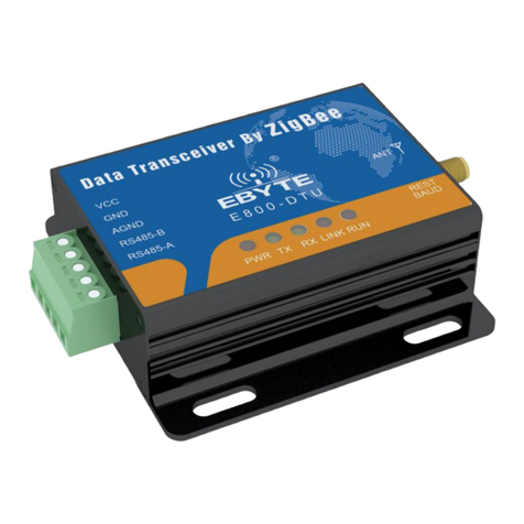
Ebyte E180-DTU User manual


Chengdu Ebyte Electronic Technology Co., Ltd E180-DTU(ZG120-485) Usermanual
Copyright ©2012–2019,
Chengdu Ebyte Electronic Technology Co.,Ltd 1
Contents
1 Product introduction............................................................................................................................................................ 3
1.1 Brief introduction..................................................................................................................................................... 3
1.2 Features.................................................................................................................................................................... 3
1.3 Product features........................................................................................................................................................3
2 Size and pin definition......................................................................................................................................................... 4
2.1 Pin definition............................................................................................................................................................ 5
2.2 Size........................................................................................................................................................................... 6
3 Interface definition...............................................................................................................................................................7
3.1 Power supply interface............................................................................................................................................. 7
4 Function description............................................................................................................................................................ 7
4.1 Transmission mode.................................................................................................................................................. 7
4.2 Configuration mode..................................................................................................................................................7
4.3 Mode switch............................................................................................................................................................. 7
5 Data receiving and transmitting mode.................................................................................................................................8
5.1 Data transmitting mode............................................................................................................................................ 8
5.1.1 Broadcast mode..................................................................................................................................................... 8
5.1.2 Multicast mode......................................................................................................................................................8
5.1.3 Unicast mode.........................................................................................................................................................8
5.2 The output mode of the received data...................................................................................................................... 8
5.2.1 Transparent output.................................................................................................................................................8
5.2.2 Data+short address................................................................................................................................................ 9
5.2.3 Data+long address................................................................................................................................................. 9
5.2.4 Data+RSSI.............................................................................................................................................................9
5.2.5 Data+short address+RSSI..................................................................................................................................... 9
5.2.6 Data+long address+RSSI...................................................................................................................................... 9
6 Application function and command configuration.............................................................................................................. 9
6.1 Function....................................................................................................................................................................9
6.1.1 LINK description...................................................................................................................................................9
6.1.2 RUN description..................................................................................................................................................10
6.1.3 UART_BAUD_RESET description....................................................................................................................10
6.2 Wireless remote configuration function.................................................................................................................10
6.3 Function parameter description..............................................................................................................................10
6.4 HEX command.......................................................................................................................................................12
6.4.1 Command rules................................................................................................................................................... 12
6.4.2 Read command.................................................................................................................................................... 13
6.4.3 Configuration command......................................................................................................................................14
6.4.4 Network operation command.............................................................................................................................. 15
6.5 HEX parameter description....................................................................................................................................16
6.5.1 System TX mode.................................................................................................................................................16
6.5.2 Data output.......................................................................................................................................................... 16
6.5.3 Device type..........................................................................................................................................................16
6.5.4 Network state.......................................................................................................................................................16

Chengdu Ebyte Electronic Technology Co., Ltd E180-DTU(ZG120-485) Usermanual
Copyright ©2012–2019,
Chengdu Ebyte Electronic Technology Co.,Ltd 2
6.5.5 Network PAN_ID................................................................................................................................................17
6.5.6 Network short address.........................................................................................................................................17
6.5.7 MAC address.......................................................................................................................................................17
6.6.8 Parent node network short address......................................................................................................................17
6.5.9 Parent node MAC address...................................................................................................................................17
6.5.10 Network group number..................................................................................................................................... 17
6.5.11 Network channel............................................................................................................................................... 17
6.5.12 TX power...........................................................................................................................................................18
6.5.13 Serial port baudrate........................................................................................................................................... 18
6.5.14 Sleep time..........................................................................................................................................................18
6.5.15 Saving time of parent node................................................................................................................................18
6.5.16 Centralized network open time......................................................................................................................... 18
6.5.17 The cycle of network reconnection after the parent node is lost.......................................................................19
6.5.18 Maximum number of reconnections................................................................................................................. 19
6.5.19 Remote configuration ID...................................................................................................................................19
6.5.20 Configure all network parameters..................................................................................................................... 19
6.5.21 Read all network parameters............................................................................................................................. 19
6.5.22 Terminals of parent node...................................................................................................................................20
6.5.23 Terminal details of parent node.........................................................................................................................20
7 Quick Start......................................................................................................................................................................... 20
7.1 Quickly build a ZigBee network............................................................................................................................ 20
7.2 Quickly join a ZigBee network.............................................................................................................................. 24
7.3 ZigBee network communication test......................................................................................................................26
7.3.1 Unicast test.......................................................................................................................................................... 26
7.3.1.1 Unicast between the terminal and the coordinator with short addresses................................................. 26
7.3.1.2 Unicast between the terminal and the coordinator with long addresses.................................................. 27
7.3.2 Multicast test....................................................................................................................................................... 28
7.3.3 Broadcast test...................................................................................................................................................... 30
8 User notice......................................................................................................................................................................... 32
8.1 Network structure...................................................................................................................................................32
9 Practical applications.........................................................................................................................................................32
10 Notice...............................................................................................................................................................................33
11 Important statement......................................................................................................................................................... 34
Revision History................................................................................................................................................................... 34
About us................................................................................................................................................................................34

Chengdu Ebyte Electronic Technology Co., Ltd E180-DTU(ZG120-485) Usermanual
Copyright ©2012–2019,
Chengdu Ebyte Electronic Technology Co.,Ltd 3
1 Product introduction
1.1 Brief introduction
E180-DTU (ZG120-485) is a wireless communication device based on ZigBee technology. As a communication
medium, like optical fiber, microwave, and cable, it has a certain scope of application: it provides real-time and reliable
data transmission of monitoring signals in a private network under certain special conditions. It has low cost, convenient
installation and maintenance, features of strong diffraction ability, flexible network structure, and long coverage range,
suitable for occasions with many points and scattered, and complicated geographical environment, can be connected to
PLC, RTU, rain gauge, level gauge and other data terminals.
1.2 Features
★All core components are imported from the original. Compared with other similar devices, they have the most
advanced functions, the smallest size, and the best price.
★Transmit power can be selected.
★It adopts temperature-compensated crystal with frequency stability better than ± 2ppm.
★Operating temperature range: -40 ℃~+ 85 ℃, can adapt to a variety of harsh working environments, truly
industrial class.
★All-aluminum alloy shell, compact size, easy installation, good heat dissipation; perfect shielding design, good
electromagnetic compatibility, strong anti-interference ability.
★Multiple protection functions, such as reverse power protection, over-connection protection, and antenna surge
protection, greatly increase the reliability of the device.
★Powerful software function, all parameters can be set by software: such as transmit power, frequency, address ID,
etc.
★Built-in watchdog and precise time layout. Once an exception occurs, the module will automatically restart and
continue to work according to the previous parameter settings.
1.3 Product features
Centralized network management: ZIGBEE 3.0 security standard centralized network access mechanism, data
is safe and reliable;
Interoperability: Zigbee 3.0 standard network mechanism, compatible with ZHA, ZLL and other network
protocols;
Large capacity: 256K flash, 32K RAM, network nodes can be expanded to more than 100;

Chengdu Ebyte Electronic Technology Co., Ltd E180-DTU(ZG120-485) Usermanual
Copyright ©2012–2019,
Chengdu Ebyte Electronic Technology Co.,Ltd 4
Role switching: The user can switch the roles between the three types of coordinator, router, and terminal
through serial commands;
Support multiple network topologies: point-to-point, star network, MESH network;
Network self-healing: When the network intermediate node is lost, other networks automatically join or
maintain the original network;
Automatic routing: module supports network routing function;
Address search: users can find the corresponding short address according to the MAC address (unique, fixed)
of the node that has joined the network, and can also find the corresponding long address of each node in the
network according to the short address;
Data security: integrated ZIGBEE 3.0 security communication standard, the network contains multi-level
security keys;
Serial port configuration: The module has built-in serial port commands. Users can configure (check) the
parameters and functions of the module through the serial port commands;
Network PAN_ID change: The network PAN_ID can be switched arbitrarily. The user can customize the
PAN_ID to join the corresponding network or automatically select the PAN_ID to join the network;
Network opening time is configurable: It can be configured to open the network for a certain period of time.
During this period, devices that comply with the ZigBee 3.0 standard can join the network. After this period of
time, the network will be shut down and any device cannot join. It can also be configured to be permanently
open, and any device that complies with the ZigBee 3.0 standard can join;
One-click restore baud rate: If the user forgets or does not know the baud rate, this function can be used to
restore the default baud rate of 115200;
Module reset: users can reset the module through serial commands;
Restore factory settings: users can restore the factory settings of the module through serial commands;
Over-the-air configuration: Users can remotely configure other devices on the network using over-the-air
configuration commands.
2 Size and pin definition

Chengdu Ebyte Electronic Technology Co., Ltd E180-DTU(ZG120-485) Usermanual
Copyright ©2012–2019,
Chengdu Ebyte Electronic Technology Co.,Ltd 5
2.1 Pin definition
No.
Item
Function
Description
1
VCC
Crimped power connector,
positive
DC 8 ~ 28V, 12V or 24V is recommended
2
GND
Crimped power connector,
negative
The negative of the power supply is connected to the
system ground and the case
3
AGND
Public ground interface
It can be connected to external grounding terminal or not
handled
4
RS485-B
Serial terminal
Output, connected to port B of other RS485 device
5
RS485-A
Serial terminal
Input, connected to port A of other RS485 device
6
PWR-LED
Power Indicator
Red, always on when power is on
7
TXD-LED
Send indicator
Yellow, blinking when sending data
8
RXD-LED
Receive indicator
Yellow, blinking when receiving data
9
LINK-LED
Connection indicator
Red, always on when connected to the network, off when
not connected
10
RUN-LED
Device working status
indicator
Red, the device is busy when the light is off, and the
device is idle when the light is on
11
Baud rate reset
switch
Tact Switch
Long press for more than 1s to reset the baud rate
(115200)
12
Antenna interface
SMA-K interface
Externally threaded female hole, 10mm long,
characteristic impedance 50Ω

Chengdu Ebyte Electronic Technology Co., Ltd E180-DTU(ZG120-485) Usermanual
Copyright ©2012–2019,
Chengdu Ebyte Electronic Technology Co.,Ltd 7
Unit: mm
3 Interface definition
3.1 Power supply interface
The user needs to use the VCC terminal and GND terminal in ①for power supply. E180-DTU can use 8 ~ 28V DC
power supply. It is recommended to use 12V or 24V DC power supply.
★Note: The communication is not smooth when the radio is connected to multiple devices, but not when connected to a
single device. Please try to connect a 120Ω resistor in parallel between the 485_A terminal and 485_B.
4 Function description
4.1 Transmission mode
When the module enters the transmission mode, any data received by the serial port will be sent out. The
transmission mode is the wireless communication between network nodes. The communication methods include unicast,
broadcast, and multicast.
4.2 Configuration mode
When the module enters the configuration mode, the data received by the serial port is defaulted to the configuration
command to configure and operate the device. In the configuration mode, the data received by the module serial port is
considered to be HEX command.
4.3 Mode switch
After the module is powered on, it defaults to be in the transmission mode.

Chengdu Ebyte Electronic Technology Co., Ltd E180-DTU(ZG120-485) Usermanual
Copyright ©2012–2019,
Chengdu Ebyte Electronic Technology Co.,Ltd 8
In the transmission mode, when the module serial port receives the "2A 2D 2E" character, it enters the configuration
mode, and returns to the "7A 7D 7E" character after successfully entering the configuration mode. In configuration mode,
when the module serial port receives the "2F 2C 2B" character, the module exits the configuration mode, enters the
transmission mode, and returns to the "7F 7C 7B" character after successfully entering the transmission mode.
5 Data receiving and transmitting mode
5.1 Data transmitting mode
The data transmission mode of the module includes unicast, broadcast and multicast.
5.1.1 Broadcast mode
In broadcast mode, the sending device sends the data received by the serial port to each node (including itself) in the
network, and all devices in the network will receive the data.
5.1.2 Multicast mode
In multicast mode, first set the group number (for grouping) for the devices in the network. The sending device must
specify the target group number (to which group to send the data). Then the sending device will send the data received by
the serial port to the network, and the devices with the same group number in the network will receive the data.
5.1.3 Unicast mode
In unicast mode, the devices on the network perform point-to-point communication through the network address. The
sending device sends the received serial data to the target address device. After receiving the data, the device with target
address can return an ACK to the sending device to indicate that it has received data.
5.2 The output mode of the received data
The output mode of received data refers to the method of serial port outputting data after the module receives
wireless data.
5.2.1 Transparent output
If the output mode of the device is transparent output, the module will output the original data through the serial port

Chengdu Ebyte Electronic Technology Co., Ltd E180-DTU(ZG120-485) Usermanual
Copyright ©2012–2019,
Chengdu Ebyte Electronic Technology Co.,Ltd 9
after receiving the wireless data.
5.2.2 Data+short address
When the output mode of the device is data + short address, after the module receives the wireless data, the serial port
will output the original data + short address of the sending device.
5.2.3 Data+long address
When the output mode of the device is data + long address, after the module receives the wireless data, the serial port
will output the original data + long address of the sending device.
5.2.4 Data+RSSI
When the output mode of the device is data + RSSI, after the module receives the wireless data, the serial port will
output the original data + RSSI value of the received packet.
5.2.5 Data+short address+RSSI
When the output mode of the device is data + short address + RSSI, after the module receives the wireless data, the
serial port will output the original data + short address of the sending device + RSSI value of the received packet.
5.2.6 Data+long address+RSSI
When the output mode of the device is data + long address + RSSI, after the module receives the wireless data, the
serial port will output the original data + long address of the sending device + RSSI value of the received packet.
Note: The sender's single packet supports a maximum data packet length of 72 bytes.
6 Application function and command configuration
6.1 Function
6.1.1 LINK description
LINK pin indicates the current network status of the module. After the device is successfully connected to the

Chengdu Ebyte Electronic Technology Co., Ltd E180-DTU(ZG120-485) Usermanual
Copyright ©2012–2019,
Chengdu Ebyte Electronic Technology Co.,Ltd 10
network, the LINK light is always on. When the device has no network or the parent node is lost, the LINK light is off.
In the coordinator mode, this pin indicates whether the module has established a network normally.
6.1.2 RUN description
RUN pin indicates the current working status of the device. When the RUN light is off, it indicates that the device is
busy; when the RUN light is on, it indicates that the device is idle; when the device receives data, the RUN light goes off
for 2 to 4 ms, and the serial port starts to output data.
6.1.3 UART_BAUD_RESET description
UART_BAUD_RESET is used to reset the device baud rate. Press and hold for more than 1s to reset the radio baud
rate (115200), 8N1.
6.2 Wireless remote configuration function
The module supports the remote configuration function. The two-byte wireless configuration ID defaults to A8 8A.
The user can modify the remote configuration ID of the module. When the first two bytes of the wireless data received
by the module are the wireless configuration ID, The module will recognize the data packet as a remote configuration
command and perform the corresponding command operation. The data packet will not be output through the serial port.
6.3 Function parameter description
The module provides abundant configurable parameters, which can be flexibly used according to actual application
requirements to build different forms of networks.
Configuration
information
Attributes
Parameter
range
Description
PANID
Read/Write
0x0000~0xFFFF
PANID is the identifier of the ZIGBEE network and is used
to determine the identity of the network to which it belongs. All
devices in the same network must have the same PANID. When
the terminal or router is configured as 0xFFFF, it can be added
to any network that already exists on the same channel.
Local network
address
Read
0x0000~0xFFFF
It is used to distinguish each node in the network. When
each device is in the same network, the local network address
must be unique. When not connected to the network, the
device's network address is 0xFFFF. After joining the network,
the short address of the device is assigned by the coordinator .
The coordinator address is fixed: 0x0000.
Network status
Read
0、1、2、3、4
Represents the network status of the current device: no

Chengdu Ebyte Electronic Technology Co., Ltd E180-DTU(ZG120-485) Usermanual
Copyright ©2012–2019,
Chengdu Ebyte Electronic Technology Co.,Ltd 11
network, currently joining the network, has successfully joined
the network, has a network but has lost its parent node, is
leaving the current network, etc.
Target network
address
Read/Write
0x0000~0xFFFF
Current device communication target (short address),
which can be switched at any time through commands
Local MAC address
Read
64bitMAC
The factory default MAC address of the module which
cannot be changed by the user
Target MAC address
Read/Write
64bitMAC
Send data using long address in fixed mode
Device type
Read/Write
C、R、E、S
They are: coordinator, router, non-dormant terminal,
dormant terminal
Channel
Read/Write
CH11~26
Working physical channel of ZIGBEE device
Transmitting mode
Read/Write
0、1、2、3
Module transmitting modes: broadcast mode, multicast
mode, short address unicast mode, long address unicast mode
For details, please refer to the corresponding mode
introduction.
Output mode
Read/Write
0、1、2、3、4、
5
The data output modes of the module are:
Transparent transmission;
Data+short address;
Data+long address;
Data+RSSI;
Data+short address+RSSI;
Data+long address+RSSI
TX power
Read/Write
0~20dbm
Output power of the module: 0 to 20dbm. Where power
consumption is required and the distance is not required, the tx
power can be reduced for saving average power consumption.
Remote configuration
ID
Read/Write
2 bytes
It is used to judge whether the data received in the air is a
remote configuration command. Customers can change the
wireless configuration ID according to their needs. The default
is A8 8A。
Local network
group number
Read/Write
0~255
It is used to configure the group number of the device in
the network.
Target network
group number
Read/Write
0~255
It is used to configure the group number of the
corresponding target in multicast mode.
Network opening time
Read/Write
10~2540 second
It is used to configure the opening and closing of network
security. Devices can join the network during opening, and
devices cannot join during closing.
Reconnection cycle
when the parent node
is lost
Read/Write
1~255 minute
When the parent node is lost (coordinator is powered off),
the terminal device reconnects to the previous network at
regular intervals.
Maximum number of
reconnections
Read/Write
1~255 次
It is the maximum number of reconnections after the parent
node is lost. If the reconnection is not successful, the previous
network information is cleared and the new network is
rescanned. The scanning cycle is equal to the reconnection
cycle.

Chengdu Ebyte Electronic Technology Co., Ltd E180-DTU(ZG120-485) Usermanual
Copyright ©2012–2019,
Chengdu Ebyte Electronic Technology Co.,Ltd 12
6.4 HEX command
6.4.1 Command rules
Read format of local serial port:
Network parameter reading: FE LEN CMD FF
Peripheral parameter reading: FE LEN CMD CHANNEL FF
FE: Fixed head
LEN: Length of DATA
CMD: Actual name ID
CHANNEL: PWM、ADC、GPIO Channel selection when reading
FF: Command Terminator
Read return format: FB CMD DATA
FB: Fixed head
CMD: Command ID
DATA:Parameter
Local serial port configuration format: FD LEN CMD DATA FF
FD:Fixed head
LEN: Length of DATA
CMD: Actual name ID
DATA:Parameter
FF: Command Terminator
Return of configuration: FA CMD
FA:Fixed head
CMD: Command ID
Return during reading / configuration: F7 FF, indicating that the information does not exist / read / configuration /
format failed.
Wireless remote read / configuration format: Add wireless configuration ID before the command format of local
serial port mode
The default is A8 8A (its value can be modified), for example:
Configuration format: A8 8A FD LEN CMD DATA FF
Parameter reading format: A8 8A FE LEN CMD (CHANNEL) FF
Network operation format:F5 LEN CMD DATA FF
F5: Fixed head
LEN: Length of DATA
CMD: Actual name ID
DATA: Parameter
FF: Command Terminator
Return of configuration: FC CMD STATUS
FC: Fixed head

Chengdu Ebyte Electronic Technology Co., Ltd E180-DTU(ZG120-485) Usermanual
Copyright ©2012–2019,
Chengdu Ebyte Electronic Technology Co.,Ltd 13
CMD: Actual name ID
STATUS: 00 Successful, 01 failed
6.4.2 Read command
Command
description
Command
ID
Command format
Example
Read device type
01
Send:FE 01 01 FF
Return:FB 01 dev_type
Send:FE 01 01 FF
Return:FB 01 03
Read network status
02
Send:FE 01 02 FF
Return:FB 02 nwk_state
Send:FE 01 02 FF
Return:FB 02 02
Read network
PAN_ID
03
Send:FE 02 03 FF
Return:FB 03 pan_id
Send:FE 02 03 FF
Return:FB 03 FE 5B
Read local network
short address
05
Send:FE 02 05 FF
Return:FB 05 Short_Addr
Send:FE 02 05 FF
Return:FB 05 F6 FA
Read local MAC
address
06
Send:FE 08 06 FF
Return:FB 06 Mac_Addr
Send:FE 08 06 FF
Return:FB 06 1F 1C 21 FE
FF 57 B4 14
Read network short
address of parent
node
07
Send:FE 02 07 FF
Return:FB 07 Coor_shortAddr
Send:FE 02 07 FF
Return:FB 07 00 00
Read the MAC
address of the parent
node
08
Send:FE 08 08 FF
Return:FB 08 Coor _Mac_Addr
Send:FE 08 08 FF
Return:FB 08 0C 46 0C FE
FF 9F FD 90
Read network group
number
09
Send:FE 01 09 FF
Return:FB 09 group
Send:FE 01 09 FF
Return:FB 09 01
Read communication
channel
0A
Send:FE 01 0A FF
Return:FB 0A channel
Send:FE 01 0A FF
Return:FB 0A 0B
Read tx power
0B
Send:FE 01 0B FF
Return:FB 0B txpower
Send:FE 01 0B FF
Return:FB 0B 0A
Read serial port baud
rate
0C
Send:FE 01 0C FF
Return:FB 0C baud
Send:FE 01 0C FF
Return:FB 0C 09
Read sleep time
0D
Send:FE 01 0D FF
Return:FB 0D sleep_time
Send:FE 01 0D FF
Return:FB 0D 54
Read the short
network address of
the target
23
Send:FE 02 23 FF
Return:FB 23 Dec_ShortAddr
Send:FE 02 23 FF
Return:FB 23 00 00
Read the network
group number of the
target
24
Send:FE 01 24 FF
Return:FB 24 Dec_netid
Send:FE 01 24 FF
Return:FB 24 00
Read the long
address of the target
25
Send:FE 08 25 FF
Return:FB 25 Dec_mac
Send:FE 08 25 FF
Return :FB 25 0A 1C 21

Chengdu Ebyte Electronic Technology Co., Ltd E180-DTU(ZG120-485) Usermanual
Copyright ©2012–2019,
Chengdu Ebyte Electronic Technology Co.,Ltd 14
FE FF 57 B4 14
Read system send
mode
26
Send:FE 01 26 FF
Return:FB 26 send_mode
Send:FE 01 26 FF
Return:FB 26 02
Read data output
mode
27
Send:FE 01 27 FF
Return:FB 27 out_mode
Send:FE 01 27 FF
Return:FB 27 00
Read central network
open time
28
Send:FE 01 28 FF
Return:FB 28 net_opentime
Send:FE 01 28 FF
Return:FB 28 FF
The cycle of
reconnection when
the parent node lost
29
Send:FE 01 29 FF
Return:FB 29 net_rejoinperiod
Send:FE 01 29 FF
Return:FB 29 05
Maximum number of
reconnections when
the parent node lost
30
Send:FE 01 30 FF
Return:FB 30 net_rejoincount
Send:FE 01 30 FF
Return:FB 30 05
Read wireless
configuration ID
31
Send:FE 02 31 FF
Return:FB 31 header
Send:FE 02 31 FF
Return:FB 31 A8 8A
Read all network
parameters of the
device
FE
Send:FE 2F FE FF
Return:FB FE all_info
Send:FE 2F FE FF
Return:FB FE 03 02 FE 5B
F6 FA 1F 1C 21 FE FF 57
B4 14 00 00 0C 46 0C FE
FF 9F FD 90 01 0B 0A 09
54 00 00 00 0A 1C 21 FE FF
57 B4 14 02 00 FF 05 05 A8
8A
Read the number of
parent nodes
32
Command:FE 01 32 FF
Return:FB 32 child_count
Send:FE 01 32 FF
Return:FB 32 0A
Read the parent
node's detail list
33
Command:FE 0E 33 FF
Return:FB 33 index dev_type
Short_Addr Mac_Addr
Send:FE 0E 33 FF
Return:FB 33 00 03 FE 5B
0A 1C 21 FE FF 57 B4 14
6.4.3 Configuration command
Configure device type
Send:FD 01 01 dev_type FF
Return:FA 01
Send:FD 01 01 03 FF
Return:FA 01
Configure PAN_ID
Send:FD 02 03 pan_id FF
Return:FA 03
Send:FD 02 03 FE 5B FF
Return:FA 03
Configure network group number
Send:FD 01 09 group FF
Return:FA 09
Send:FD 01 09 01 FF
Return:FA 09
Configure communication channel
Send:FD 01 0A channel FF
Return:FA 0A
Send:FD 01 0A 0B FF
Return:FA 0A
Configure TX power
Send:FD 01 0B txpower FF
Return:FA 0B
Send:FD 01 0B 0A FF
Return:FA 0B
Configure serial port baud rate
Send:FD 01 0C baud FF
Send:FD 01 0C 09 FF

Chengdu Ebyte Electronic Technology Co., Ltd E180-DTU(ZG120-485) Usermanual
Copyright ©2012–2019,
Chengdu Ebyte Electronic Technology Co.,Ltd 15
Return:FA 0C
Return:FA 0C
Configure sleep time
(terminal valid)
Send:FD 01 0D sleep_time FF
Return:FA 0D
Send:FD 01 0D 54 FF
Return:FA 0D
Configure short address of target
network
Send:FD 02 23 dec_addr FF
Return:FA 23
Send:FD 02 23 00 00 FF
Return:FA 23
Configure group number of target
network
Send:FD 01 24 netid FF
Return:FA 24
Send:FD 01 24 00 FF
Return:FA 24
Configure long address of target
network
Send:FD 08 25 dec_mac FF
Return:FA 25
Send:FD 08 25 0A 1C 21
FE FF 57 B4 14 FF
Return:FA 25
Configure system TX mode
Send:FD 01 26 mode FF
Return:FA 26
Send:FD 01 26 02 FF
Return:FA 26
Configure data output mode
Send:FD 01 27 mode FF
Return:FA 27
Send:FD 01 27 00 FF
Return:FA 26
Configure the time of opening
centralized network
Send:FD 01 28 time FF
Return:FA 28
Send:FD 01 28 FF FF
Return:FA 28
Configure the rejoin period after
the terminal node loses the parent
node
Send:FD 01 29 time FF
Return:FA 29
Send:FD 01 29 05 FF
Return:FA 29
Configure the maximum number
of rejoin after the terminal node
loses the parent no
Send:FD 01 30 time FF
Return:FA 30
Send:FD 01 30 05 FF
Return:FA 30
Configure remote configuration ID
Send:FD 02 31 header FF
Return:FA 31
Send:FD 02 31 A8 8A FF
Return:FA 31
Configure all network parameters
Send:FD 1A FE all_info FF
Return:FA FE
Send:FD 1A FE 03 FE 5B
01 0B 0A 09 54 00 00 00 0A
1C 21 FE FF 57 B4 14 02 00
FF 05 05 A8 8A FF
Return:FA FE
Device reset
Send:FD 00 12 FF
Return:FA 12
Send:FD 01 12 FF
Return:FA 12
Restore to factory settings
Send:FD 00 13 FF
Return:FA 13
Send:FD 01 13 FF
Return:FA 13
6.4.4 Network operation command
Open network
Send:F5 01 40 01 FF
Return:FC 40 00
Send:F5 01 40 01 FF
Return:FC 40 00
Leave network
Send:F5 01 40 02 FF
Return:FC 40 00
Send:F5 01 40 02 FF
Return:FC 40 00
Create new network
Send:F5 01 40 03 FF
Return:FC 40 00
Send:F5 01 40 03 FF
Return:FC 40 00

Chengdu Ebyte Electronic Technology Co., Ltd E180-DTU(ZG120-485) Usermanual
Copyright ©2012–2019,
Chengdu Ebyte Electronic Technology Co.,Ltd 16
Start Touchlink
Send:F5 01 40 04 FF
Return:FC 40 00
Send:F5 01 40 04 FF
Return:FC 40 00
6.5 HEX parameter description
6.5.1 System TX mode
Mode:
0x00 Broadcast (default);
0x01 Multicast;
0x02 Unicast+short address;
0x03 Unicast+long address.
6.5.2 Data output
Mode:
0x00 Transparent transmission (Default);
0x01 Data+short address;
0x02 Data+long address;
0x03 Data+RSSI;
0x04 Data+short address+RSSI;
0x05 Data+long address+RSSI.
Note: the maximum packet length is 72 bytes
6.5.3 Device type
dev_type:
0x01 Coordinator
0x02 Router
0x03 Terminal (default)
Changing the device type configuration takes effect after restarting. If the device type is configured in normal
operation, the device will leave the current network and be in a no-network state. After restarting, it will switch to the
changed device type.
6.5.4 Network state
nwk_state:
0x00 No network

Chengdu Ebyte Electronic Technology Co., Ltd E180-DTU(ZG120-485) Usermanual
Copyright ©2012–2019,
Chengdu Ebyte Electronic Technology Co.,Ltd 17
0x01 Joining the network currently
0x02 Has joined the network
0x03 A network exists, but the parent node is lost
0x04 Leaving the current network
6.5.5 Network PAN_ID
pan_id:
0x0000~0xFFFE Fixed network PAN_ID
0xFFFF Random network PAN_ID
PANID This parameter needs to be configured before establishing a network or joining a network
6.5.6 Network short address
Short_Addr: 2 Byte Addresses randomly assigned by the coordinator
6.5.7 MAC address
Mac_Addr: 8 Byte Factory unique physical address, fixed
6.6.8 Parent node network short address
Coor_shortAddr: 2 Byte The short address of the parent node of the current device, it is 0x0000 if the coordinator
6.5.9 Parent node MAC address
Coor_Mac_Addr: 8 Byte Long address of the parent node of the current device
6.5.10 Network group number
Group: Group number range 0x01~0xFF (default 0 means no group, the system broadcasts by default)
6.5.11 Network channel
Channel: channel range 0x0B(11)~0x1A(26)(default 11 channel)
This parameter needs to be configured before joining the network or establishing a network.

Chengdu Ebyte Electronic Technology Co., Ltd E180-DTU(ZG120-485) Usermanual
Copyright ©2012–2019,
Chengdu Ebyte Electronic Technology Co.,Ltd 18
6.5.12 TX power
Txpower: TX power level (default 10dBm)
Adjustable range 0~20dbm
This parameter needs to be configured before joining the network or establishing a network.
6.5.13 Serial port baudrate
Baudrate parameter table:
To change the baud rate of serial communication, it takes effect after restarting the device.
6.5.14 Sleep time
sleep_time: (1~60) Sleep wake cycle 1~60 Unit (second)
(61~255) Sleep wake cycle 60+(61-60)*10~60+(255-60)*10 Unit (second)
Note: This sleep time represents the polling cycle of the terminal and represents the speed at which the terminal
automatically switches the best parent node.
6.5.15 Saving time of parent node
Time: The maximum setting of the Zigbee protocol stack is 30, and the unit is S (seconds). If a terminal node needs
to receive data from the parent node, the configuration of the sleep time cannot be longer than 30 seconds.
6.5.16 Centralized network open time
Open time: (1~254) Network open time range is (1~254)*10 Unit (second)
255 Indicates that the network is permanently open
Buad
Baudrate
Buad
Baudrate
01
4800
08
76800
02
9600
09
115200 (default)
03
14400
0A
128000
04
19200
05
38400
06
50000
07
57600

Chengdu Ebyte Electronic Technology Co., Ltd E180-DTU(ZG120-485) Usermanual
Copyright ©2012–2019,
Chengdu Ebyte Electronic Technology Co.,Ltd 19
6.5.17 The cycle of network reconnection after the parent node is lost
Rejoin period: (1~255) Reconnection cycle range 1~255 Unit (minute)
6.5.18 Maximum number of reconnections
Rejoin maxcount: (1~255) Range of Maximum number of reconnections: 1~255 times
Note: After attempting the maximum number of rejoins, if the previous network has not been restored, the previous
network information will be cleared, and the new network is scanned periodically with the Rejoin period. The power
consumption of scanning the new network is higher than restoring the power consumption of the previous network.
Devices with high power consumption requirements need to set the Rejoin period and Rejoin maxcount parameters to a
larger value. The default value is 5.
6.5.19 Remote configuration ID
Remote Header: 0x0000 is to turn off remote configuration, 0x0001~0xFFFF is to turn on remote configuration,
default is 0xA88A(0xA8 0x8A).
6.5.20 Configure all network parameters
all_info: FD 1A FE 03 FE 5B 01 0B 0A 09 54 00 00 00 0A 1C 21 FE FF 57 B4 14 02 00 FF 05 05 A8 8A FF
Device type 03; Network PANID FE 5B; Network group number 01; Channel 0B; TX power 0A; Baudrate 09; Sleep
time 54; Target network short address 00 00; Target network group number 00; Target network short address 0A 1C 21
FE FF 57 B4 14; System TX mode 02; Data output way 00; Network open time FF; Rejoin cycle 05; Rejoin times 05;
Remote ID A8 8A.
6.5.21 Read all network parameters
all_info:FB FE 03 02 FE 5B F6 FA 1F 1C 21 FE FF 57 B4 14 00 00 0C 46 0C FE FF 9F FD 90 01 0B 0A 09 54 00
00 00 0A 1C 21 FE FF 57 B4 14 02 00 FF 05 05 A8 8A
Device type 03; Network state 02; Network PANID FE 5B; Local network short address F6 FA; Local MAC address 1F
1C 21 FE FF 57 B4 14; Parent node network short address 00 00; Parent node MAC address 0C 46 0C FE FF 9F FD 90;
Network group number 01; Channel 0B; TX power 0A; Baudrate 09; Sleep time 54; Target network short address 00 00;
Target network group number 00; Target network long address 0A 1C 21 FE FF 57 B4 14; System TX mode 02; Data
output way 00; Network open time FF; Rejoin cycle 05; Rejoin times 05; Remote ID A8 8A.
Other manuals for E180-DTU
3
This manual suits for next models
1
Table of contents
Other Ebyte Modem manuals

Ebyte
Ebyte E890-470LG27 User manual

Ebyte
Ebyte E851-RTU User manual

Ebyte
Ebyte M02-XACX0420 User manual

Ebyte
Ebyte E90-DTU User manual

Ebyte
Ebyte E890-868LG12 User manual

Ebyte
Ebyte E95-DTU User manual

Ebyte
Ebyte E32-DTU User manual

Ebyte
Ebyte E180-DTU User manual

Ebyte
Ebyte ECAN-U01 User manual

Ebyte
Ebyte MA02-AAC 2220 Series User manual

Ebyte
Ebyte ECAN-U01S User manual

Ebyte
Ebyte E180-DTU User manual

Ebyte
Ebyte E90-DTU User manual

Ebyte
Ebyte E821-RTU User manual

Ebyte
Ebyte E90-DTU User manual

Ebyte
Ebyte E180-DTU User manual

Ebyte
Ebyte NA111-A User manual

Ebyte
Ebyte ME31-XXAX0060 User manual

Ebyte
Ebyte E90-DTU User manual

Ebyte
Ebyte E95-DTU User manual