Ebyte EA01-D User manual

0
IOT Serial Module
EA01-D

Copyright ©2012–2020, Chengdu Ebyte Electronic Technology Co.,Ltd
1
Chengdu Ebyte Electronic Technology Co.,Ltd. EAO1-D user manual
Content
1 Product Overview................................................................................................................................................................ 2
1.1 Brief Introduction...................................................................................................................................................... 2
1.2 Features ...............................................................................................................................................................2
1.3 Parameter ............................................................................................................................................................... 2
1.4 Interface description.................................................................................................................................................. 3
1.5 Pin definition............................................................................................................................................................. 4
2 Quick Start........................................................................................................................................................................... 5
2.1 Hardware preparation................................................................................................................................................ 5
2.2 Data transmission test................................................................................................................................................ 6
3 Command Configuration and Function Explanation........................................................................................................... 7
3.1AT mode and data transparent transmission mode switch......................................................................................... 7
3.2Device software restart............................................................................................................................................... 7
3.2
Application of power saving lock WORKLOCK..................................................................................................7
3.3
Serial port baud rate setting................................................................................................................................... 8
3.4
Communication protocol type configuration.........................................................................................................8
3.5
TCP/UDP transparent transmission channel function configuration.....................................................................9
3.5.1
TCP/UDP address and port configuration.................................................................................................. 9
3.5.2
Turn on and off TCP/UDP socket0 connection..........................................................................................9
3.6
Heartbeat packet function configuration............................................................................................................. 10
3.6.1
Configure TCP/UDP heartbeat packet content.........................................................................................10
3.6.2
Send heartbeat packet command.............................................................................................................. 10
3.6.3
Registration packet function configuration.............................................................................................. 10
3.6.4
Custom registration package data content configuration......................................................................... 11
3.7
Modbus RTU/TCP conversion function..............................................................................................................11
3.7.1
Modbus RTU/TCP enable configuration..................................................................................................11
3.8
MQTT application configuration.........................................................................................................................12
3.8.1
Instructions for using MQTT command set............................................................................................. 12
3.8.2
MQTT mode configuration...................................................................................................................... 12
3.8.3
MQTT address and port configuration..................................................................................................... 12
3.8.4
Three elements configuration of MQTT connection................................................................................13
3.8.5
MQTT subscription topic configuration...................................................................................................15
3.8.6
MQTT publish topic configuration.......................................................................................................... 15
3.8.7
MQTT and server keepalive settings........................................................................................................16
3.9
COAP function configuration..............................................................................................................................16
3.9.1
COAP function description...................................................................................................................... 16
3.9.2
COAP address parameter configuration...................................................................................................16
3.9.3
Command for adding option to COAP message...................................................................................... 17
3.9.4
Command for adding token in COAP message........................................................................................18
3.9.5
Command for removing the option or token in the message....................................................................18
3.9.6
Command for COAP message without payload.......................................................................................18
3.9.7
COAP data receiving description............................................................................................................. 19
4 Ebyte cloud function configuration..................................................................................................................................... 19
4.1Address and port configuration................................................................................................................................ 19
Important Statement..............................................................................................................................................................21
Revision History................................................................................................................................................................... 21

About us................................................................................................................................................................................ 21


Copyright ©2012–2020, Chengdu Ebyte Electronic Technology Co.,Ltd
2
Chengdu Ebyte Electronic Technology Co.,Ltd. EAO1-D user manual
1 Product Overview
1.1 Brief Introduction
EA01-D is a NB-IOT data transmission module developed by Ebyte for the purpose of realizing mutual data transmission between
serial device and network server merely by user simple setting. It supports B3, B5, and B8 frequency bands. The module is well
equipped with software and functions, covering most of general application scenarios. It is often used in wireless meter reading, shared
bicycles, smart parking, smart city, security, asset tracking, smart home appliances, wearable devices, agricultural and environmental
monitoring and other industries to provide comprehensive data transmission services.
The module is designed with 2.0mm pin to facilitate customer’s device integration, with 5V ~ 18V power supply or lithium
battery power supply. It supports China Mobile, China Unicom, Telecom NB card, adopts compatible level for communication and
LED indication, default 3.3V applicable to 5V level, with anti-interference ability. It is adaptable to environment with strong
electromagnetic interference, such as some electric power fields.
1.2 Features
Work at B3 B5 B8 frequency band
Support data transparent transmission, TCP/UDP transparent transmission; support heartbeat packet, registration packet function
Support TCP, UDP, MQTT, COAP, LwM2M and other protocols;
Support two Socket connections sending and receiving simultaneously;
SupportModbusRTU/TCPconversion
Support SMS in PDU format;
Support FOTA remote upgrade
Support Telecom Cloud CTWING, Huawei Cloud OceanConnect, Unicom Cloud, China Mobile OneNet Cloud Platform, Alibaba
Cloud, Baidu Cloud, and Ebyte Cloud transparent transmission;
Support PSM, eDRX;
Support NB-IoT radio communication protocol 3GPP standard Rel.13, Rel.14.
1.3 Parameter
)
)
Parameter
Value
Description
Features
Working frequency
B3 B5 B8 frequency band
Automatically search for frequency
NB data features
Single-tone:25.5kbps (download), 16.7kbps (upload)
Multi-tone:25.5kbps (download), 62.5kbps (upload)

Copyright ©2012–2020, Chengdu Ebyte Electronic Technology Co.,Ltd
3
Chengdu Ebyte Electronic Technology Co.,Ltd. EAO1-D user manual
Network protocol
features
Support TCP, UDP, MQTT, COAP, LwM2M and
other protocols;
Hardware
features
Antenna type
IPEX
Baud rate
Max 115200bps, default 9600bps
Transmitting power
20dBm±2dB
Current
consumption
(typ.)
Sending current: 345 mA (5V)
Receiving current: 30 mA (5V)
Operating Voltage
DC 5V~18V Lithium battery direct drive: 3.6V~4.3V
Operating temperature
Normal operating temperature -30°C to +75°C
Limit operating temperature -40°C to +85°C
Operating humidity
RH5%~RH95%
Size
42×40×9mm
1.4 Interface description

Copyright ©2012–2020, Chengdu Ebyte Electronic Technology Co.,Ltd
4
Chengdu Ebyte Electronic Technology Co.,Ltd. EAO1-D user manual
1.5 Pin definition
No.
Pin
Description
1
RST
Reset, valid in low level
2
IO_RT
If low level lasts about 1 second, the factory settings will be restored and the automatic restart will take
effect.
3
LIKA
Socket0 connection status indicator: corresponding to the
onboard left LED light 1.
High: Socket0 is successfully connected to the network server
Low: Socket0 fails to be connected to the network server;
4
LIKB
Socket1 connection status indicator: corresponding to the
onboard left LED light 2.
High: Socket1 is successfully connected to the network server
Low: Socket1 fails to be connected to the network server;
5
DATA
Socket data receiving and sending status indicator: When data is received by network or when data is
received by serial port, the indicator light flashes, corresponding to the onboard left LED light 3.
6
NET
Device network status indicator: corresponding to the onboard right LED light 1.
When the device is attaching to the network, it flashes rapidly;
After the device is successfully attached to the network, it flashes slowly;
7
RXD
Data receiving indicator: default 3.3V, compatible with 5V communication level.
8
TXD
Data sending indicator: default 3.3V, compatible with 5V communication level.
9
VEF
Drive level power supply indicator: 5V level is input in order to achieve serial communication and LED
indicator as 5V drive level.
10, 11, 14,
15, 23, 24,
25
NC
NC, unavailable
12
4V2
Lithium battery power supply indicator, power supply range: 3.6V~4.3V, type: 3.8V. Reverse pin
connection and power supply together with VCC are prohibited.
16
VCC
DC power supply indicator: power supply range: 5V~18V. Reverse pin connection and power supply
together with 4V2 are prohibited.
19
VD
External SIM card power supply indicator: NC is available if the onboard SIM card holder is used.
20
RS
External SIM card reset indicator: NC is available if the onboard SIM card holder is used.
21
DA
External SIM card data indicator: NC is available if the onboard SIM card holder is used.
22
CL
External SIM card signal indicator: NC is available if the onboard SIM card holder is used.
13, 17, 18
GND
Power Ground

2 Quick Start
2.1 Preparation for use
The hardware devices required for this test are as follows:
Before testing, please connect the serial cable, SIM card (insert the notch outwards), antenna and other related devices. Details are as
follows:
EA01-D
5V-18V power adapter or 4.2V lithium
battery
USB to TTL
module
Sucker antenna and IPEX to SMA
Cable
5

Copyright ©2012–2020, Chengdu Ebyte Electronic Technology Co.,Ltd
6
2.2 Data transmission test
Before the test, please be sure that the power supply, antenna, SIM card (insert the notch outwards), serial cable and other hardware are well
connected.
(1) Visit the official website of Ebyte: www.ebyte.com via PC browser, download the latest serial port tool, install the USB to serial driver, and run the
software;
(2) Select the corresponding COM No., the default serial port baud rate is 9600, 8N1, and configure the module by following the user manual;
(3) Check the signal strength, and set the device connection server IP and port No. as: 116.62.42.192, 8124; (Ebyte test server);
(4) Restart the module and await the device LINK light to be on;
(5) Follow the WeChat official account of "Ebyte" on the mobile phone, enter the page, and click in turn: Customer Support -> Device Test, as
shown in the below screenshot of the mobile phone page.
1. Send data using PC serial port tool, and send data to the device with mobile phone. The communication test results are shown in the following
figure:

Copyright ©2012–2020, Chengdu Ebyte Electronic Technology Co.,Ltd
7
3 Command Configuration and Function Explanation
3.1 AT mode and data transparent transmission mode switch
AT command
Response
ATD*98/r/n
CONNECTI
NG
OK
+++
OK
(1) Power-on defaults to work in AT command mode. In AT command mode, send ATD*98\r\n or ATD*99\r\n to switch
(2) <+++>:Transparent transmission mode: In transparent transmission mode, the last three bytes of user data are "+++", or three bytes
"+++" are sent after user data transmission is completed, the transparent transmission mode will end.
3.2 Device software restart
AT command
Response
AT+NRB/r/n
REBOOTI
NG
After inputting the AT command, the device will restart, and the AT parameters will be saved in the flash at the same time. When
the AT parameters need to be memorized after power-off, first configure the parameters through the AT command, and then input
the AT+NRB command to save the parameters to the flash.
3.3 Applicationofpowersavinglock WORKLOCK
AT Command
Response
AT+WORKLOCK
=<enable>/r/n
OK
(1) Ifmodule is in deep sleep mode for a long time (chip power down state), in order to ensure that the data interaction fails to enter deepsleep
ahead of time during the application period, input AT+WORKLOCK =1 and add work lock to prevent it from entering deep sleep in
advance. After data interaction is completed, input AT+WORKLOCK=0 to release the lock, then module will enter deep sleep.
(2) The module supports serial port wake-up, which can be waked up by inputting AT command. After the AT command wakes up the
module, the work lock will be automatically added. Therefore, after each wake-up for business interaction, you must enter
AT+WORKLOCK=0 to release the lock to enter deep sleep.
Note: You must also enter AT+WORKLOCK=0 to enter deep sleep after powering on again

Copyright ©2012–2020, Chengdu Ebyte Electronic Technology Co.,Ltd
8
3.4 Serial port baud rate settings
AT Command
Response
AT+UARTSET =<rate>,<store>/r/n
OK
(1) This command is similar to the function of remote "at + NATSPEED", which is used to set the baud rate of at serial port and other
parameters. The default value is 9600 baud rate. When the store is 0, the baud rate will take effect dynamically. When the store is 1, the set
baud rate will be divided by 2400 and saved in flash, and will be automatically restarted。
(2) Description of parameter configuration
◆<rate>: The baud rate, the highest 115200 currently supported.
◆<store>: whether to save; default to not to save, that is, to dynamically switch the baud rate; If it is set to 1, it is saved in NV and
restarted immediately; If it is set to 0, it means that the dynamic effect is valid and the baud rate of the other party needs to be switched
synchronously.
3.5 Communication protocol type configuration
AT Command
Response
AT+PDUTYPE=<pdu_type>/r/n
OK
AT+PDUTYPE/r/n
type:<pdu_type>
OK
(1) Currently, MQTT,COAP, and TCP/UDP are supported. Currently, the module supports two sockets, and allows TCP/UDP and one of MQTT,
COAP and Ebyte Cloud to communicate at the same time. TCP/ODP always opens socket0, and one of MQTT and COAP opens socket1.
(2) Configuration Parameter Description
◆<pdu_type>,0 indicates TCP or UDP based protocol, 1 indicates MQTT based protocol, and 2 indicates COAP based
protocol. 3 indicates Ebyte cloud protocol.
When youneed tosave after power-off, input AT+NRB command to save the parameters to the flash, and automatically restart to take effect.

Copyright ©2012–2020, Chengdu Ebyte Electronic Technology Co.,Ltd
9
3.5 Functional Configuration of TCP/UDP Passthrough Channel
3.5.1TCP/UDP Address and Port Configuration
AT Command
Respond
AT+SOCKADDR =<addr>,<port>,<local_port>,<type>
/r/n
OK
AT+SOCKADDR /r/n
address:< addr >,port:< port >,local port:
<local_port>,type:<type>
OK
(1) The socket0 address support the IP address and the domain name, the maximum byte length supports 50 byte, the soft restart,
hardware reset and normal power-on of the equipment are automatically connected with the socket0, If the server does not release the link
before connection, the terminal needs to disconnect the link successfully first and then connect to socket0.
(2) Configuration Parameter Description
◆<addr>,which supportsIP addresses or domainnames, with a maximum byte length of 50 bytes.
◆<Port>, the port of the remote server.
◆<local_port>, local port, 0 means freely selected by tcpip, default is 0.
◆<type>, 0 indicates the TCP protocol, 1 indicates the UDP protocol.
When youneed tosave after power-off, input AT+NRB command to save the parameters to the flash, and automatically restart to take effect.
(3) Actively reporting +XSSTATE:<id>,<state> when Socket connection state changes;
◆<id> Indicates the created socket ID. Currently, only 0 and 1 are supported. TCP/DUP channels can only use 0, and COAP, MQTT, and
Ebyte cloud channels use 1.
◆<state> indicates the socket connection state, 1 indicates the connection state, and 0 indicates the disconnection state.
For example, socket0 will actively report + XSSTATE: 0,1 after successful connection, and will actively report + XSSTATE:0,0 when the
server or terminal disconnects socket0.
3.5.2 Turn on and off TCP/UDP connections to socket0
AT Command
Respond
AT+SOCKONOFF=<enable>,<on-off>/r/n
+XSSTATE:< id>,<state>
OK
◆<enable>, indicates whether the TCP/UDP channel is enabled, 1 indicates enabled, and 0 indicates not enabled. The default is to enable open
TCP/UDP channels.
◆<on-off>, which turns socket0 on or off, 1 on, 0 off.
When youneed tosave after power-off, input AT+NRB command to save the parameters to the flash, and automatically restart to take effect.
.

Copyright ©2012–2020, Chengdu Ebyte Electronic Technology Co.,Ltd
10
3.6 Configuration of heartbeat pack function
3.6.1 Configure TCP/UDP Heartbeat Packet Content
AT Command
Respond
AT+HEARTINFO=<type>,<data>/r/n
OK
AT+HEARTINFO /r/n
<data>
OK
◆<type >, 0 means the heartbeat bag type is in HEX format, 1 means the heartbeat type is in ASCII code (string) format.
◆<data>,refers to the data content of the transmitted heartbeat packet. The maximum length is less than 40. The
default value is "Ebyte NB IoT heart rate data" .
When you need to save after power-off, input AT+NRB command to save the parameters to the flash, and automatically restart to take effect.
3.6.2 Send Heartbeat Packet Command
AT Command
Respond
AT+SENDHEART=<send>/r/n
OK
(1) Input at command AT + SENDHEART = 1, then the sending of heartbeat packet can be completed.
(2) If PDU _ type selects TCP/UDP, the TCP/UDP heartbeat packet will be sent; if MQTT is selected, the MQTT heartbeat packet will
be sent ("PINGRESP" will be printed on the serial port after successful sending); Ebyte cloud heartbeat packet will be sent if Ebyte cloud is
selected.
3.6.3 Registration Package Mode Configuration
AT Command
Respond
AT+REGMOD=<mode>/r/n
OK
AT+REGMOD/r/n
OK
mode: <mode>
◆<mode>, 0 indicates that the registration packet is closed, 1 indicates that the IMEI registration packet is added before each packet of
data sent; 2 means that a custom registration packet is added before each packet of data to be sent; 3 means that an IMEI registration
packet is sent only when the server is linked for the first time;4 means that a custom registration packet is sent only the first time it is
linked to the server.
When you need to save after power-off, input AT+NRB command to save the parameters to the flash, and automatically restart to take effect.

Copyright ©2012–2020, Chengdu Ebyte Electronic Technology Co.,Ltd
11
3.6.4 Custom registration package data content configuration
AT Command
Respond
AT+REGINFO=<type>,<data>/r/n
OK
AT+REGINFO /r/n
OK
< data >
◆<type>, 0 indicates that the registration package type is in HEX format, and 1 indicates that the registration package type is in ASCII code
(string) format.
◆<data>,refers to the data content of the registration packet sent. The maximum length is less than 40. The default value is "Ebyte Register
packet".
When you need to save after power-off, input AT+NRB command to save the parameters to the flash, and automatically restart to take effect.
3.7 Modbus RTU/TCP conversion function
Function Description
After the Modbus RTU/TCP conversion function is on, under the receiving state, when the data format of the Modbus RTU is wirelessly received,
the data format is automatically converted into the data format of the Modbus TCP for serial port print; In that transmit state, when the serial port
receives the data format of the Modbus RTU, the data format is automatically converted into the data format of the Modbus TCP for wireless
transmission;
3.7.1 Modbus RTU/TCP Enable Configuration
AT Command
Respond
AT+MODBUS=<enable>,<Id> /r/n
OK
AT+MODBUS /r/n
OK
enable:< enable>,Id:< Id >
(1) Description of parameter configuration
◆<enable>, 0 turns off the Modbus RTU/TCP conversion function, and 1 turns on the Modbus RTU/TCP conversion function.
◆<Id>, indicating the Modbus TCP transaction identifier, (0 ~ 65535) 2 bytes in length.
(2) Transaction ID Id Function Description
◆Under the Modbus TCP to Modbus RTU state, when Id = 0, any received Modbus TCP will be converted to the corresponding RTU
protocol, otherwise only the transaction ID matches.
◆When the Modbus RTU is in the state of being converted to Modbus TCP, it indicates the ID ofthe converted Modbus TCP transaction.
When you need to save after power-off, input AT+NRB command to save the parameters to the flash, and automatically restart to take effect.

Copyright ©2012–2020, Chengdu Ebyte Electronic Technology Co.,Ltd
12
3.8 MQTT Application Configuration
3.8.1 Instructions for Using MQTT Instruction Set
First, AT+MQTTMODE command configures the working mode soft reset of MOTT to be re-enabled; secondly, AT+PDUTYPE confirms
whether the data frame type is MQTT transmission or not; thirdly, AT+MQTTCONN configures the three elements of the connection; again,
AT+MQTTSUBTOP and AT+MQTTPUBTOP command configures the subject of subscription and publication. Finally, the ATD * 98 enters the
transmission mode for service interaction. After the interaction is completed, the + + + is input to enter AT command mode. The
AT+WORKLOCK=0 command is input to release the lock and enter the deep sleep mode.
3.8.2 MQTT Mode Configuration
AT Command
Respond
AT+MQTTMODE=<mode>/r/n
OK
AT+MQTTMODE /r/n
OK
mode:< mode >
◆<type>, means to disable the MQTT function, 1 means to access the Alibaba Cloud platform, 2 means to access the OneNet platform
and other Internet of Things platforms that support the standard MQTT protocol, and 3 means to access Baidu Cloud platform.
When you need to save after power-off, input AT+NRB command to save the parameters to the flash, and automatically restart to take effect.
3.8.3 MQTT Address and Port Configuration
AT Command
Respond
AT+MQTTADDR=<addr>,<port>/r/n
OK
AT+MQTTADDR /r/n
OK
address: <addr>,port: <port>
(1) When the MQTT mode is 0, entering this instruction will prompt " MQTT closed" ";When the MQTT mode is 1, configure the address and
port of the Alibaba Cloud Platform; When the MQTT mode is 2, configure the address and port of OneNet platform or other platforms; When
the MQTT mode is 3, configure the address and port of Baidu cloud platform;
Note: Baidu cloud, OneNet, MQTT three platform domain name address generally will not change, if the domain name really changes can
also be modified by instructions.
(2) Description of parameter configuration
◆<addr>, which represents the IP address or domain name of the server and has a maximum length of 50 bytes.
◆<port>, represents the server port.

Copyright ©2012–2020, Chengdu Ebyte Electronic Technology Co.,Ltd
13
3.8.4 Configuration of Three Elements of MQTT Connection
AT Command
Respond
AT+MQTTCONN=<value0>,<value1>,<value2>/r/n
OK
AT+MQTTCONN /r/n
OK
<value0>
<value1>
<value2>
(1) The length of each of the three elements is not more than 40 bytes.
(2) Refer to the corresponding application guidance for the description of the three element values of each platform.
◆Alibaba Cloud Platform, value0, indicating the Product Key “1PbEeweXIm” is as shown in the below screenshot.
Value1 represents that device name “ebyte_nbiot_door_senor” is shown in the below screenshot.
Value2 represents password, calculated by MQTT signature tool provided by Alibaba Cloud, and the signature results is input in value2.
Among them, the value of productkey\deviceName\deviceSecret can be checked in the device shown in below screenshot.

Copyright ©2012–2020, Chengdu Ebyte Electronic Technology Co.,Ltd
14
clientID is 460046671104253|securemode=3,signmethod=hmacsha1|, |securemode=3, signmethod=hmacsha1| is a fixed value.
460046671104253 isobtained byAT+CIMI withNo.CIMInumberofthecard.
◆On Baidu Cloud platform, value0 represents the name entered when creating a new object shadow such as "ebyte_nbiot_xy", value1 indicates the user
name such as "7nzgctm/ebyte_nbiot_xy", value2 indicates the key in the object shadow connection configuration
◆OneNet platform, value0 indicates the device ID as shown in the screenshot below
Value1 indicates the product ID, as shown in the screenshot below.

Copyright ©2012–2020, Chengdu Ebyte Electronic Technology Co.,Ltd
15
Value2 is the authentication information of the device, as shown in the screenshot.
When you need to save after power-off, input AT+NRB command to save the parameters to the flash, and automatically restart to take effect.
3.8.5 MQTT subscription topic configuration
AT Command
Respond
AT+MQTTSUBTOP=< topicName>,<qos>/r/n
OK
AT+MQTTSUBTOP /r/n
OK
qos:< qos >
< topicName>
◆<topicName>: a string within 200 bytes of the content of the subscription topic.
◆<qos>: quality service support QoS = 0, QoS = 1, QoS = 2.
3.8.6 MQTT publishing topic configuration
AT Command
Respond
AT+MQTTPUBTOP=< topicName>,<qos>/r/n
OK
AT+MQTTPUBTOP /r/n
OK
qos:< qos >
< topicName>
◆<topicName>: a string within 200 bytes of the content of the publication topic.
◆<qos>: quality service support QoS = 0, QoS = 1, QoS = 2.

Copyright ©2012–2020, Chengdu Ebyte Electronic Technology Co.,Ltd
16
3.8.7 MQTT and Server keepalives Settings
AT Command
Respond
AT+MQTTALIVE=< alive_time >/r/n
OK
AT+MQTTALIVE /r/n
OK
keep alive time:< alive_time >
◆<alive_time> : The time to keep the server alive, the unit is second, the data range is 2 bytes, the default is 600
seconds (10minutes).
When you need to save after power-off, input AT+NRB command to save the parameters to the flash, and automatically restart to take effect.
3.9 COAP function configuration
3.9.1 COAP Function Description
◆At first, AT+COAPADDR command configures address and port of COAP server and opens COAP function at the same time, AT+NRB soft reset
restarts to be effective;
◆Second, AT + PDUTYPE instruction selects the data protocol type as COAP
◆Thirdly, AT+ADDOPTION, AT+ADDTOKEN and AT+COAPMINUS instructions add or delete option or token in the message;
◆Finally, AT+COAPHEADER instruction sends the message without load; ATD*98 enters the transparent transmission mode to input
serial port transparent transmission data. At this time, the data to be sent is loaded COAP message (serial port transparent transmission
data is the payload of COAP message).
3.9.2 COAP Address Parameter Configuration
AT Command
Respond
AT+COAPADDR=<addr>,<port>,<local_port>,<enable>/r/n
OK
AT+COAPADDR /r/n
OK
address: <addr>,port: <port>,local port:<
local_port >,enable<enable>
◆<addr>, supporting IP address or domain name, maximum byte length 50 bytes
◆<port>, the port of the server
◆<local_port>, local port
◆<enable>, COAP enable, 0 means to turn off COAP function, 1 means to turn on COAP function
When you need to save after power-off, input AT+NRB command to save the parameters to the flash, and automatically restart to take effect.

Copyright ©2012–2020, Chengdu Ebyte Electronic Technology Co.,Ltd
17
3.9.3 Instruction for adding option in COAP message
AT Command
Respond
AT+ADDOPTION=<index>,< type>,< value>/r/n
OK
AT+ADDOPTION /r/n
OK
index:<index>,type:<type>,
value:<value>
◆<index>,the sequence number of option, range 0 to 7, the maximum number of options can be configured, and the storage space is 1024 bytes.
◆<type>, the number of option, as shown in the following figure.
For example, type = 11 indicates that the option resource type is Uri-Path.
◆<value>, the specific content of the option, for example, the specific value of the Uri-Path option is \ temperature. If the data type of value
is Uint, the data range is 0-4294967295, and the data length is only Holds 0-4 bytes. A plurality of options can be configured, and the
maximum number of options can be 8. For example, enter the following commands in turn:
AT+ADDOPTION=0,3, iot.eclipse.org
AT+ADDOPTION=1,7, 5683
AT+ADDOPTION=2,11,\temperature
AT+ADDOPTION read instruction return
index: 0,type: 3, value: iot.eclipse.org
index:1, type: 7, value: 5683
index: 2,type: 11, value: \temperature

Copyright ©2012–2020, Chengdu Ebyte Electronic Technology Co.,Ltd
18
3.9.4 InstructionsforAdding Tokenin COAPMessage
AT Command
Respond
AT+ADDTOKEN =<token>/r/n
OK
AT+ADDTOKEN /r/n
OK
<token>
◆<token>, and the data format is HEX.
The parameter to be entered in the column is 0x7A5B69EF
AT+ADDTOKEN=7A5B69EF
Read instruction
AT+ADDTOKEN
AT+ADDTOKEN
7A5B69EF
3.9.5 Remove theoption ortoken instructionfrom themessage
AT Command
Respond
AT+COAPMINUS=<token>,<option>/r/n
OK
◆<token> =1, remove the token in the message
◆<option>=1, remove the option in the message
3.9.6 Send command of COAP without payload message
AT Command
Respond
AT+COAPHEADER =<type>,<code>/r/n
OK
AT+COAPHEADER /r/n
OK
type:<token>,code:<code>
◆<type>, Configure the type of the sent message.
Type=0, CON frame, a request that needs to be acknowledged, if a con request is sent, then the other party must respond.
Type=1, NON frame, a request that does not need to be acknowledged, if a non request is sent, then the other party does not have to respond
Type=2, ACK frame, acknowledgement message, response to the con message.
Type=3, RST frame, Reset message, when the message received by the receiver contains an error, the receiver parses the message or no
longer cares what the sender sent, then the reset message will be sent.

Copyright ©2012–2020, Chengdu Ebyte Electronic Technology Co.,Ltd
19
◆<code>, Configure the function code for sending the message
code =1, get method, used to get a resource
code =2, POST method, used to create a resource
code =3, PUT method, used to update a resource
code =4, DELETE method, used to delete a resource
For example, if AT+COAPHEADER =0,1 is input, a frame of COAP get message can be sent. The message includes a fixed header and may
have option or token.
3.9.7 COAP Data Receiving Instruction
◆The serial port prints the Head information of the received COAP data frame: response code: < code >, type: <type >, tid: < tid > ends with
carriage return and line feed.
< code>, indicating the function code of the server response;< type >, indicating the type of the received message;< tid >, indicating the
message ID (decimal format) of the received message.
◆If there is token in the received message, the serial port prints the token: < token > ends with carriage return and line feed, and < token > is
in the form of HEX string.
◆If there is option in the received message, the serial port prints option type: < type >, value: < value > and ends with carriage return and
line feed.
◆If there is Payload in the received message, the serial port prints Payload: < Payload > ends with carriage return and line feed.
4 Ebyte Cloud Function Configuration
4.1 Address and port configuration
AT Command
Respond
AT+EIOTADDR=<addr>,<port>/r/n
OK
AT+EIOTADDR /r/n
OK
address: <addr>, port: <port>
◆<addr>, Support IP address or domain name, the maximum byte length is 50 bytes.
◆<port>, Server port
4.1.1
Turn on/off andSNconfiguration
AT Command
Respond
AT+EIOT=<onoff>, <keysn>/r/n
OK
AT+EIOT /r/n
OK
onoff: <onoff>,keysn: <keysn>
◆<onoff>, 1 means turn on the connection to the Ebyte Cloud, 0 means turn off the connection to the Ebyte Cloud.
Table of contents
Other Ebyte Network Hardware manuals

Ebyte
Ebyte EA01-SG User manual

Ebyte
Ebyte E01-ML01IPX User manual

Ebyte
Ebyte E103-W10 User manual

Ebyte
Ebyte E83-2G4M03S User manual

Ebyte
Ebyte E810-TTL-CAN01 User manual

Ebyte
Ebyte E104-BT12NSP User manual

Ebyte
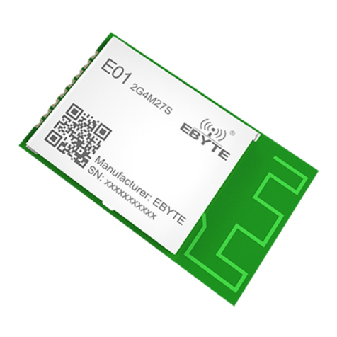
Ebyte E01-2G4M27S User manual

Ebyte
Ebyte E22-900MM22S Installation instructions

Ebyte
Ebyte MBL Series User manual
Popular Network Hardware manuals by other brands

Iomega
Iomega StorCenter ix12 user guide

DPS Telecom
DPS Telecom NetGuardian 16A user manual

HIK VISION
HIK VISION HiWatch Series quick start guide

Data Conversion Systems
Data Conversion Systems DCS Network Bridges user manual

Planet
Planet NVR-401 user manual

Cabletron Systems
Cabletron Systems FLIU-1 installation guide