manuals.online logo
Brands
  1. Home
  2. •
  3. Brands
  4. •
  5. Panasonic
  6. •
  7. Switch
  8. •
  9. Panasonic SW-100 Series User manual

Panasonic SW-100 Series User manual

<In case of Minus Common>
I/O CIRCUIT DIAGRAMS
4
Main Circuit
12 to 24V DC
±10%
+
-
Load
Load
Load
+V
Output 1_1
Output 1_2
Output 2_1
Output 2_2
Output 3_1
Output 3_2
0V
Terminal No.
Internal circuit Users’ circuit
*1
External input
indicator 2
External input
indicator 1
External input
circuit 2
External input
circuit 1
External input 2
External input 1
Switching terminal of
time-out function (IN)
Switching terminal of
time-out function (+V)
<In case of Plus Common>
12 to 24V DC
±10%
+
-
+V
0V
Terminal No.
Main Circuit
Load
Load
Load
Output 1_1
Output 1_2
Output 2_1
Output 2_2
Output 3_1
Output 3_2
Internal circuit Users’ circuit
External input
indicator 2
External input
circuit 2
External input
indicator 1
External input
circuit 1
External input 2
External input 1 *1
Switching terminal of
time-out function (IN)
Switching terminal of
time-out function (+V)
*1
Non-voltage contact or NPN open-collector transistor, PNP open-collector transistor
or or
0 to 1V or 10V to +V: Valid (External input indicator lights up )
4 to 6V or Open: Invalid (External input indicator turns OFF)
<Bottom of the product (Unit: mm)>
M30 × 1.5
80
80
2. Makesuretotamountingpacking(ac-
cessory)totheterminalareaofthemain
bodyrst,thenputthemainbodyintothe
mountingplate.(Note1)
Main body
Mounting packing
(Accessory)
Mounting nut
(Accessory)
Mounting tool
SW-MT1
(Optional)
Mounting
plate
Notes:1)Makesuretousethemountingpacking(accessory),orwaterproofpropertywillbe
invalid.
2) AmountingtoolSW-MT1forfasteningthemountingnutisavailableseparately.
TheshapeoffasteningpartofSW-MT1 is M10 nut.
3) Whenusingtheproductsfortwo-handcontrol, be sure to mount the productsby
complyingwithISO13851(EN574,JISB9712)andANSIB11.1,B11.9. In ad-
dition,besuretouseacontrollerfortwo-handcontrolwhich complies with ISO
13851(EN574,JISB9712).
<Fitting diagram of the mounting packing>
Mounting packing
(Accessory)
3. Fastenamountingnut(accessory)from
the reverse side of the mounting plate.
(Note 2)
The tightening torque should be 2 to
3N·m.
FUNCTIONAL DESCRIPTION
2
1.
Operation indicator
(Green)
1.
Operation indicator
(Green)
3. Fault indicator
(Yellow)
2. Power indicator
(Green)
4.
External input
indicator 1
(Green)
5.
External input
indicator 2
(Orange)
4.
External input
indicator 1
(Green)
5.
External input
indicator 2
(Orange)
4. External input
indicator 1
(Green)
5. External
input
indicator 2
(Orange)
6. Sensing
surface
8.
B side terminal
block
7.
A side terminal
block
Designation Function
1Operation indicator
× 2 (Green) Lightsupwhenanobjectisdetected.
2Powerindicator
(Green) LightsupwhenthepowerisON.
3Fault indicator
(Yellow)
Blinksorlightsupwhenfaultoccurs.
Referto“ TROUBLESHOOTING”fordetailsinblink-
ing operation.
4External input indi-
cator 1 × 3 (Green)
Lightsupwhenexternalinput1isvalid.
Referto“ FUNCTIONS”fordetails.
5
External input indica-
tor 2 × 4 (Orange)
Lightsupwhenexternalinput2isvalid.
Referto“ FUNCTIONS”fordetails.
6Sensingsurface
Thru-beamtypephotoelectricsensorisincorporatedinthesensing
surface.Thus,whenthelightbeamisinterruptedbyngers,thesensor
goesintothebeaminterruptedconditionandoutputturnsONorOFF.
7
Asideterminalblock
Connects +V, output 1, 2 and 0V.
8
Bsideterminalblock
Connectsswitchingterminalsoftime-outfunction,output
3, and external input 1, 2.
● Thisproductisanopticaltouchswitchwhichdetectsahand
byathru-beamtypephotoelectricsensor.
● Whenahandistouchedtothesensingsurface,outputturns
ON or OFF.
OUTLINE
1
● Followtheproceduresbelowwhenmountingthisproductonamountingplate.
MOUNTING
3
1. Drillaholeinamountingplate(thickness:3mmorless.)
Procedures
Dimensions of a mounting hole
to be drilled when mounting on
a metal plate (Unit: mm)
Dimensions of a mounting hole
to be drilled when mounting on
a resin plate (Unit: mm)
4.8+0.2
0
33
+0.5
0
ø30.5
+0.5
0
4.8+0.2
0
ø30.5
+0.5
0
18.4 +0.5
0
33
+0.5
0
10.2 +0.5
0
R4±0.1R4±0.1
WARNING
● Neverusethisproductinadeviceforpersonnelprotection.
● Incaseofusingdevicesforpersonnelprotection,useproductswhichmeetlawsandstandards,
suchasOSHA,ANSIorIECetc.,forpersonnelprotectionapplicableineachregionorcountry.
● Donotusethisproductasadeviceforemergencystop.
● Thisproductisusedtostartupthemachinery.Securingsafetyforthestart-
upofmachineryshouldbeperformedseparately.
● Whenusingtheproductsfortwo-handcontrol,complywiththefollowingcontents.
• Selectamodelofacontroldevicefortwo-handcontrol,basedonresultsofriskassessment.
• Make sure to use a controller for two-hand control which complies with
ISO13851(EN574.)
• Foranotherrequirements suchas mountingof thisproduct, orprevention of
accidentalactuationandofdefeatetc.,complywithISO13851(EN574,JIS
B9712)andANSIB11.1,B11.9.Furthermore,complywiththeregulationses-
tablishedbynationalorregionalsecuritycommittees(OccupationalSafetyand
HealthAdministration:OSHA,theEuropeanStandardizationCommittee,etc.)
INSTRUCTION MANUAL
Optical Touch Switch
SW-101
MJE-SW101No.0055-94V
ThankyouverymuchforpurchasingPanasonicproducts.ReadthisInstruction
Manualcarefullyandthoroughlyforthecorrectandoptimumuseofthisproduct.
Kindlykeepthismanualinaconvenientplaceforquickreference.
Ramco National
www.PanasonicSensors.com
1-800-280-6933
1. Basic operation
● When a hand is touched to the sensing surface, thru-beam
type photoelectric sensor detects the hand, and output turns
ON or OFF.
FUNCTIONS
5
2. Output
● ThreesemiconductorphotoMOSrelaysareincorporated.
Output1 :Whenanobjectisdetected(beamisinterrupted): OFF /
  Whenanobjectisnotdetected(beamisreceived): ON
Output2,3:Whenanobjectisdetected(beamisinterrupted)):ON/
  Whenanobjectisnotdetected(beamisreceived): OFF
Note:Whenthepowerofthethru-beamtypephotoelectricsensorinsidethemainbodyturns
ONinbeaminterruptedcondition,output1turnsON,whileoutputs2and3turnOFF,
thenthefaultindicator(yellow)lightsup.Inthiscase,oncebeamisreceived,thefault
indicatorturnsOFFandthesensorreturnstonormaloperation.
3. Time-out function
● Unintendedbeaminterruptedconditioncausedbydirtonthesensingsurface,
etc.canbemonitored.
• Whenbeaminterruptedcondition(sensingcondition)continuesfor10sec.
ormore,output1turnsON,whileoutput2and3turnOFF(outputcondition
isthesameasnon-sensingcondition.)
• Thisfunctioncanbeinvalidbyshort-circuiting“betweenswitchingterminals
oftime-outfunction(terminalNo.7andNo.8)”asdescribedbelow.
Note:Whentime-outfunctionis operated, the fault indicator (yellow) lightsup.Inthiscase,
oncebeamisreceived,thefaultindicatorturnsOFFandthesensorreturnstonormal
operation.
Short-circuit between the switching
terminals of time-out function
7 8
4. External input function
● External input indicators 1 and 2 of this product light up by the signal from
external input.
External input indicators 1 and 2:
Lightsupwhenexternalinputindicators1and2arevalid(0to1Vor10Vto+V).
TurnsOFFwhenexternalinputindicators1and2areinvalid(4to6Voropen).
Sensing
condition
10 sec.
or more
Sensing
Non-
sensing
Turns OFF
Lights up
OFF
ON
OFF
ON
OFF
ON
Fault
indicator
Output 1
Output 2
Output
3
<Timing Chart (In case time-out function works)>
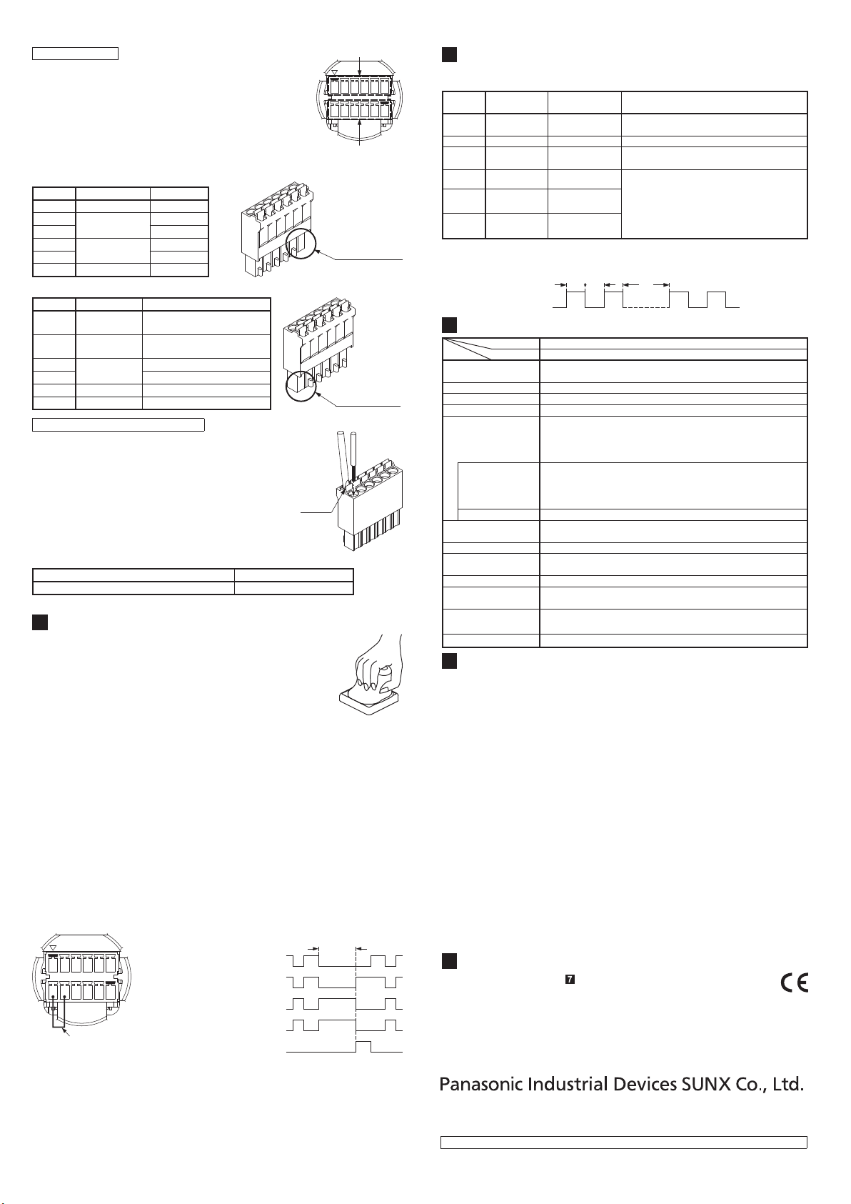
Connecting to the terminal block
● Whenconnectingtotheterminalblock,pushthecable
withferruleterminalintothebackofthemountinghole.
Ifthecableisproperlyinserted,thelockiscompleted
andthecabledoesnotfallifitispulled.
● Incaseofusingtwistedwiredirectly, hold down the
release button and plug the cable into the back as
shownintherightgure.Conformingcablediameter
isshownbelow.
● Incaseofremoving,holddownthereleasebuttonand
pull the cable.
Cablewithnoferruleterminal(Twistedwire) Cablewithferruleterminal
0.2to1.5mm2 (AWG 24 to 16) 0.2to1.5mm2
<Conforming cable>
Release
button
Terminal layout
A side terminal block
B side terminal block
<Bottom view>
1 2 3 4 5 6
789
10 11 12
● AstheshapeisdifferentbetweenAsideterminal(termi-
nalNo.1to6)andBsideterminal(terminalNo.7to12),
makesuretowireproperly.
TerminalNo.
Terminalname Description
1 12 to 24V DC +V
2Output 1 Output 1_1
3 Output 1_2
4Output 2 Output 2_1
5Output 2_2
6 0V 0V
Terminal No.1 has
no projection
<A side terminal block>
TerminalNo.
Terminalname
Description
7Timer(+V) Switchingterminal of time-
outfunction(+V)
8 Timer(IN) Switchingterminaloftime-
outfunction(IN)
9Output 3 Output 3_1
10 Output 3_2
11 IN2 (Orange) External input 2
12 IN1 (Green) External input 1
<B side terminal block>
Terminal No.12 has
no projection
Designation
Opticaltouchswitch
Item
Model No.
SW-101
Applicable standard CSA22.2No.14,CSA22.2No.0.8,ANSI/NFPA79,UL508,
EN60947-5-2(EMConly)
Sensingmethod Thru-beamtypephotoelectricsensor(2beamaxes)
Supplyvoltage 12 to 24V DC±10%, Ripple P-P10% or less
Currentconsumption 100mAorless(Excludingexternalconnectionload)
Output
SemiconductorphotoMOSrelayoutput×3
•Maximumloadcurrent:100mA
•Appliedvoltage:30VDCorless(betweenoutputand+V)
•Residualvoltage:1.5Vorless(at100mAofloadcurrent)
Output operation
Output 1 :
Whenanobjectisdetected(lightisblocked):OFF/
Whenanobjectisnotdetected(lightisreceived):ON
Output2,3:Whenanobjectisdetected(lightisblocked):ON/
Whenanobjectisnotdetected(lightisreceived):OFF
Short-circuitprotection
Incorporated
Responsetime 100msorlesswhenanobjectisdetected
50msorlesswhenanobjectisnotdetected
Protection IP65(IEC)TYPE1(UL50)(Excludingterminalarea)
Ambienttemperature -25to+50°C(Nodewcondensationoricingallowed)
Storage:-30to+70°C
Ambienthumidity 30to85%RH,Storage:30to85%RH
Material
Enclosure: Polycarbonate, Polyester resin
Nut:PBT,Moutingpacking:Siliconerubber
Connection cable
length
Upto20m(cablediameter:0.2tounder0.3mm2)
Upto100m(cablediameter:0.3ormoreto1.5mm2)
Weight Approx. 130g
SPECIFICATIONS
7
● Thisproducthasbeendeveloped/producedforindustrialuseonly.
● Conrmthewiringbeforepowerissupplied,aswrongwiringwilldamagethe
internal circuit.
● Verifythatthesupplyvoltagevariationiswithintherating.
● Ifpowerissuppliedfromacommercialswitchingregulator,ensurethattheframe
ground(F.G.)terminalofthepowersupplyisconnectedtoanactualground.
● UseapowersupplyunitconformingtotheEMCDirectiveandtheLowVoltage
Directive.(OnlyforuseinEurope)
● UseapowersupplyunitconformingtoCLASS2.(OnlyforuseintheUnitedStates)
● Useapowersupplyunitwithanoutputholdingtimeof20msormore.
● Donotuseduring theinitialtransient time(approx.300ms)afterthepower
supplyisswitchedON.
● MakesuretouseanisolationtransformerfortheDCpowersupply.Ifanauto-transformer
(singlewindingtransformer)isused,thisproductorthepowersupplymaygetdamaged.
● Incaseasurgeisgeneratedintheusedpowersupply,connectasurgeab-
sorber to the source and absorb the surge.
● MakesurethatthepowerisOFFwhilewiring.
● Do not run the wires together with high-voltage lines or power lines or put
theminthesameraceway.Thiscancausemalfunctionduetoinduction.
● Inordertoreducenoise,makethewiringasshortaspossible.
●Do not use this product in places having excessive vapor, dust, etc.
● Takecarethattheproductdoesnotcomeincontactwithoil,grease,oror-
ganic solvents such as thinner, etc.
● Donothittheproductbyahammeretc.whenmounting,astheproductgetdamaged.
● Thisproductissuitableforindooruseonly.
CAUTIONS
8
TROUBLESHOOTING
6
● Faultindicator(yellow)blinkswhenanerroroccurs.
● Anerrorcanbeidentiedbythenumberofblinksofthefaultindicator.
Blinking
number Error
Statusofsensor
Countermeasure
1Output
short-circuit Lockout Checkthewiringofoutput.
2 Dirt error
Normaloperation
Wipeoutthesensingsurfacewithasoftcloth.
4Extraneous
light error Lockout Place the product so that extraneous light
isnotreceivedatitssensingsurface.
5Internal error Lockout Check that there is no noise around the
product.Alsochecktheenvironment for
powersupplyandwiring.
Incasetheproductdoesnotoperatenormally
aftercheckingtheabovemeasures,contact
PanasonicIndustrialDevicesSUNXCo.,Ltd.
6Emission
circuit error Lockout
7Reception
circuit error Lockout
● Incaseoflockoutcondition,whenuppercountermeasureisperformed and
thepowerissuppliedagain,theoperationreturnstonormal.
0.3s0.3s
Turns OFF
Lights up 2s
<Blinking cycle of the fault indicator [(e.g.) The number of blinks: 2 times]>
●
Themodelslistedunder“ SPECIFICATIONS”comewithCEMarking.
Asforallothermodels,pleasecontactourofce.
●Contact for CE
PanasonicMarketingEuropeGmbHPanasonicTestingCenter
Winsbergring15,22525Hamburg,Germany
INTENDED PRODUCTS FOR CE MARKING
9
http://panasonic.net/id/pidsx/global
Overseas Sales Division (Head Ofce)
2431-1Ushiyama-cho,Kasugai-shi,Aichi,486-0901,Japan
Phone:+81-568-33-7861FAX:+81-568-33-8591
Forsalesnetwork,pleasevisitourwebsite.
PRINTEDINJAPAN ©PanasonicIndustrialDevicesSUNXCo.,Ltd.2016
Ramco National
www.PanasonicSensors.com
1-800-280-6933

This manual suits for next models

1

Other Panasonic Switch manuals

Panasonic GA-MLD16TPoE+ User manual

Panasonic

Panasonic GA-MLD16TPoE+ User manual

Panasonic AW-HS50N User manual

Panasonic

Panasonic AW-HS50N User manual

Panasonic SW-200 Series User manual

Panasonic

Panasonic SW-200 Series User manual

Panasonic ABJ User manual

Panasonic

Panasonic ABJ User manual

Panasonic AW-SW300 User manual

Panasonic

Panasonic AW-SW300 User manual

Panasonic PN28168 User manual

Panasonic

Panasonic PN28168 User manual

Panasonic AV-HS300 User manual

Panasonic

Panasonic AV-HS300 User manual

Panasonic ZEQUO 2200 User manual

Panasonic

Panasonic ZEQUO 2200 User manual

Panasonic WJMP204C - DATA MULTIPLEX UNIT User manual

Panasonic

Panasonic WJMP204C - DATA MULTIPLEX UNIT User manual

Panasonic AVHS300G - HD SWITCHER User manual

Panasonic

Panasonic AVHS300G - HD SWITCHER User manual

Panasonic CATU7000U - AV CTRL AMP User manual

Panasonic

Panasonic CATU7000U - AV CTRL AMP User manual

Panasonic WJ-SW104 User manual

Panasonic

Panasonic WJ-SW104 User manual

Panasonic PN28080i-TH User manual

Panasonic

Panasonic PN28080i-TH User manual

Panasonic WJ-SW208E User manual

Panasonic

Panasonic WJ-SW208E User manual

Panasonic PN28240i-NZ User manual

Panasonic

Panasonic PN28240i-NZ User manual

Panasonic GA-ML4TWPoE++ Owner's manual

Panasonic

Panasonic GA-ML4TWPoE++ Owner's manual

Panasonic S24GPWR User manual

Panasonic

Panasonic S24GPWR User manual

Panasonic PN28240i User manual

Panasonic

Panasonic PN28240i User manual

Panasonic PN28248 User manual

Panasonic

Panasonic PN28248 User manual

Panasonic GA-ML24TPoE+ User manual

Panasonic

Panasonic GA-ML24TPoE+ User manual

Panasonic WJSQ308 - SEQUENTIAL SWITCHER User manual

Panasonic

Panasonic WJSQ308 - SEQUENTIAL SWITCHER User manual

Panasonic GA-AS12TPoE+ Series User manual

Panasonic

Panasonic GA-AS12TPoE+ Series User manual

Panasonic ABV BV User manual

Panasonic

Panasonic ABV BV User manual

Panasonic AVHSB300G - HD ANALOG BOARD User manual

Panasonic

Panasonic AVHSB300G - HD ANALOG BOARD User manual

Popular Switch manuals by other brands

Qlogic QLogic 12000 Series user guide

Qlogic

Qlogic QLogic 12000 Series user guide

Qlogic SANbox 9100 Frequently asked questions

Qlogic

Qlogic SANbox 9100 Frequently asked questions

Blackmagicdesign Videohub Hardware Control Installation and operation manual

Blackmagicdesign

Blackmagicdesign Videohub Hardware Control Installation and operation manual

Digital Zone Sound Switcher installation guide

Digital Zone

Digital Zone Sound Switcher installation guide

Black Box LPB2848A Cli guide

Black Box

Black Box LPB2848A Cli guide

AVLink VAX-2044 user manual

AVLink

AVLink VAX-2044 user manual

SMART-AVI D2H-4P Quad quick start guide

SMART-AVI

SMART-AVI D2H-4P Quad quick start guide

Planet GSD-804P user manual

Planet

Planet GSD-804P user manual

Planet KVM-U201 user manual

Planet

Planet KVM-U201 user manual

BZB Gear BG-MKVM41R Quick installation guide

BZB Gear

BZB Gear BG-MKVM41R Quick installation guide

CoolGear CG-7PU31HB product manual

CoolGear

CoolGear CG-7PU31HB product manual

3One data IES716-2GS Quick installation guide

3One data

3One data IES716-2GS Quick installation guide

Black Box PI523A Multi-Port Spooler II Installation and operation manual

Black Box

Black Box PI523A Multi-Port Spooler II Installation and operation manual

AirLive IE-541POE Quick setup guide

AirLive

AirLive IE-541POE Quick setup guide

Planet FSP-804P user manual

Planet

Planet FSP-804P user manual

Planet SGSW-24040 Quick installation guide

Planet

Planet SGSW-24040 Quick installation guide

Planet FGSW-2612PVS user manual

Planet

Planet FGSW-2612PVS user manual

SHORE TEL ShoreGear 90BRI Quick install guide

SHORE TEL

SHORE TEL ShoreGear 90BRI Quick install guide

manuals.online logo
manuals.online logoBrands
  • About & Mission
  • Contact us
  • Privacy Policy
  • Terms and Conditions

Copyright 2025 Manuals.Online. All Rights Reserved.