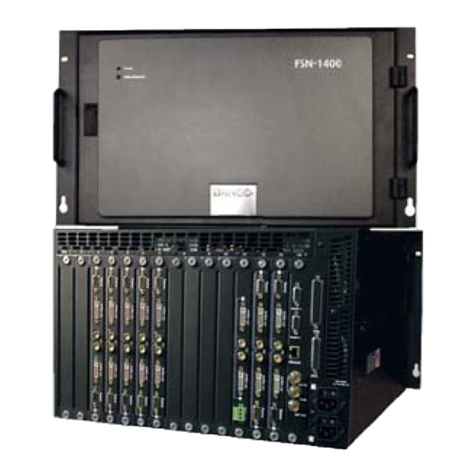
Barco FSN Series User manual

rëÉêÛë=dìáÇÉ
cpk=pÉêáÉë
•Manual #: 26-0702000-00
•Revision: 00

2FSN Series • User’s Guide
cpk=pÉêáÉë==√==rëÉêÛë=dìáÇÉ
`çéóêáÖÜí
© Barco. March 24, 2009
All rights reserved. No part of this document may be copied, reproduced or translated. It
shall not otherwise be recorded, transmitted or stored in a retrieval system without the prior
written consent of Barco.
kçíáÅÉ
Barco provides this manual “as is” without warranty of any kind, either expressed or
implied, including but not limited to the implied warranties or merchantability and fitness for
a particular purpose. Barco may make improvements and/or changes to the product(s) and/
or the program(s) described in this publication at any time without notice.
This publication could contain technical inaccuracies or typographical errors. Changes are
periodically made to the information in this publication; these changes are incorporated in
new editions of this publication.
cÉÇÉê~ä=`çããìåáÅ~íáçåë=`çããáëëáçå=Ec``F=pí~íÉãÉåí
This equipment has been tested and found to comply with the limits for a class A digital
device, pursuant to Part 15 of the FCC rules. These limits are designed to provide
reasonable protection against harmful interference when the equipment is operated in a
commercial environment. This equipment generates, uses, and can radiate radio frequency
energy and, if not installed and used in accordance with the instruction manual, may cause
harmful interference to radio communications. Operation of this equipment in a residential
area may cause harmful interference, in which case the user will be responsible for
correcting any interference.
dì~ê~åíÉÉ=~åÇ=`çãéÉåë~íáçå
Barco provides a guarantee relating to perfect manufacturing as part of the legally
stipulated terms of guarantee. On receipt, the purchaser must immediately inspect all
delivered goods for damage incurred during transport, as well as for material and
manufacturing faults Barco must be informed immediately in writing of any complaints.
The period of guarantee begins on the date of transfer of risks, in the case of special
systems and software on the date of commissioning, at latest 30 days after the transfer of
risks. In the event of justified notice of compliant, Barco can repair the fault or provide a
replacement at its own discretion within an appropriate period. If this measure proves to be
impossible or unsuccessful, the purchaser can demand a reduction in the purchase price or
cancellation of the contract. All other claims, in particular those relating to compensation for
direct or indirect damage, and also damage attributed to the operation of software as well
as to other services provided by Barco, being a component of the system or independent
service, will be deemed invalid provided the damage is not proven to be attributed to the
absence of properties guaranteed in writing or due to the intent or gross negligence or part
of Barco.
If the purchaser or a third party carries out modifications or repairs on goods delivered by
Barco, or if the goods are handled incorrectly, in particular if the systems are commissioned
operated incorrectly or if, after the transfer of risks, the goods are subject to influences not

FSN Series • User’s Guide 3
agreed upon in the contract, all guarantee claims of the purchaser will be rendered invalid.
Not included in the guarantee coverage are system failures which are attributed to
programs or special electronic circuitry provided by the purchaser, e.g. interfaces. Normal
wear as well as normal maintenance are not subject to the guarantee provided by Barco
either.
The environmental conditions as well as the servicing and maintenance regulations
specified in this manual must be complied with by the customer.
qê~ÇÉã~êâë
Brand and product names mentioned in this manual may be trademarks, registered
trademarks or copyrights of their respective holders. All brand and product names
mentioned in this manual serve as comments or examples and are not to be understood as
advertising for the products or their manufactures.
`çãé~åó=^ÇÇêÉëë
Barco, Inc.
11101 Trade Center Drive
Rancho Cordova, California 95670
USA•Phone: (916) 859-2500
•Fax: (916) 859-2515
•Website: www.barco.com
Barco N.V.
Noordlaan 5
8520 Kuurne
BELGIUM
•Phone: +32 56.36.82.11
•Fax: +32 56.35.16.51
•Website: www.barco.com
Technical Support
•Tech Line: (866) 374-7878 — 24 hours per day, 7 days per week
•E-mail: [email protected]m

4FSN Series • User’s Guide
léÉê~íçêë=p~ÑÉíó=pìãã~êó
The general safety information in this summary is for operating personnel.
aç=kçí=oÉãçîÉ=`çîÉêë=çê=m~åÉäë
There are no user-serviceable parts within the unit. Removal of the top cover will expose
dangerous voltages. To avoid personal injury, do not remove the top cover. Do not operate
the unit without the cover installed.
mçïÉê=pçìêÅÉ
This product is intended to operate from a power source that will not apply more than 230
volts rms between the supply conductors or between both supply conductor and ground. A
protective ground connection by way of grounding conductor in the power cord is essential
for safe operation.
dêçìåÇáåÖ=íÜÉ=mêçÇìÅí
This product is grounded through the grounding conductor of the power cord. To avoid
electrical shock, plug the power cord into a properly wired receptacle before connecting to
the product input or output terminals. A protective-ground connection by way of the
grounding conductor in the power cord is essential for safe operation.
rëÉ=íÜÉ=mêçéÉê=mçïÉê=`çêÇ
Use only the power cord and connector specified for your product. Use only a power cord
that is in good condition. Refer cord and connector changes to qualified service personnel.
rëÉ=íÜÉ=mêçéÉê=cìëÉ
To avoid fire hazard, use only the fuse having identical type, voltage rating, and current
rating characteristics. Refer fuse replacement to qualified service personnel.
aç=kçí=léÉê~íÉ=áå=bñéäçëáîÉ=^íãçëéÜÉêÉë
To avoid explosion, do not operate this product in an explosive atmosphere.

FSN Series • User’s Guide 5
qÉêãë=få=qÜáë=j~åì~ä=~åÇ=bèìáéãÉåí=j~êâáåÖ=
t^okfkd
Highlights an operating procedure, practice, condition, statement, etc., which, if not strictly
observed, could result in injury to or death of personnel.
`^rqflk
The exclamation point within an equilateral triangle is intended to alert the user to the
presence of important operating and maintenance (servicing) instructions in the literature
accompanying the appliance.
^sboqfppbjbkq>
Le point d´exclamation dans un triangle equilatéral signale à alerter l´utilisateur qu´il y a
des instructions d´operation et d´entretien tres importantes dans la litérature qui
accompagne l´appareil.
slopf`eq
Ein Ausrufungszeichen innerhalb eines gleichwinkeligen Dreiecks dient dazu, den
Benutzer auf wichtige Bedienungs-und Wartungsanweisungen in der Dem Great
beiliegenden Literatur aufmerksam zu machen.
Note Highlights an essential operating procedure, condition or
statement.

6FSN Series • User’s Guide
`Ü~åÖÉ=eáëíçêó
The table below lists the changes to the FSN Series User’s Guide.
Table 0-1. Change History
Rev Date ECP # Description Approved By
00 3/24/09 567874 FSN Series User’s Guide R. Pellicano

FSN Series • User’s Guide 7
q~ÄäÉ=çÑ=`çåíÉåíë
`Ü~éíÉê=N fåíêçÇìÅíáçå =K=K=K=K=K=K=K=K=K=K=K=K=K=K=K=K=K=K=K=K=K=K=K=K=K=K=K=K=K=K=K=K=K=K=K=K=K=K=K=K=K=NR
In This Chapter. . . . . . . . . . . . . . . . . . . . . . . . . . . . . . . . . . . . . . . . . . . . . . . . 15
Software Version . . . . . . . . . . . . . . . . . . . . . . . . . . . . . . . . . . . . . . . . . . . . . . 16
Chapter Structure. . . . . . . . . . . . . . . . . . . . . . . . . . . . . . . . . . . . . . . . . . . . . . 16
How to Use This Guide. . . . . . . . . . . . . . . . . . . . . . . . . . . . . . . . . . . . . . . . . . 17
Navigating . . . . . . . . . . . . . . . . . . . . . . . . . . . . . . . . . . . . . . . . . . . . . . 17
Table of Contents and Index . . . . . . . . . . . . . . . . . . . . . . . . . . . . . . . . 17
Conventions . . . . . . . . . . . . . . . . . . . . . . . . . . . . . . . . . . . . . . . . . . . . . . . . . . 17
Glossary of Switcher Terms . . . . . . . . . . . . . . . . . . . . . . . . . . . . . . . . . . . . . . 18
About the FSN Series. . . . . . . . . . . . . . . . . . . . . . . . . . . . . . . . . . . . . . . . . . . 21
Overview . . . . . . . . . . . . . . . . . . . . . . . . . . . . . . . . . . . . . . . . . . . . . . . 21
Control Features . . . . . . . . . . . . . . . . . . . . . . . . . . . . . . . . . . . . . . . . . 22
System Configuration . . . . . . . . . . . . . . . . . . . . . . . . . . . . . . . . . . . . . 23
Basic FSN Series System. . . . . . . . . . . . . . . . . . . . . . . . . . . 23
Required and Optional Cards . . . . . . . . . . . . . . . . . . . . . . . . 23
M/E Features. . . . . . . . . . . . . . . . . . . . . . . . . . . . . . . . . . . . . 24
Connectivity Diagrams . . . . . . . . . . . . . . . . . . . . . . . . . . . . . . . . . . . . . . . . . . 25
System 1 — Basic . . . . . . . . . . . . . . . . . . . . . . . . . . . . . . . . . . . . . . . . 25
System 2 — Multiple Destinations. . . . . . . . . . . . . . . . . . . . . . . . . . . . 26
Application Questions. . . . . . . . . . . . . . . . . . . . . . . . . . . . . . . . . . . . . . . . . . . 26
`Ü~éíÉê=O cpkJNQMM=lêáÉåí~íáçå =K=K=K=K=K=K=K=K=K=K=K=K=K=K=K=K=K=K=K=K=K=K=K=K=K=K=K=K=K=K=K=OT
In This Chapter. . . . . . . . . . . . . . . . . . . . . . . . . . . . . . . . . . . . . . . . . . . . . . . . 27
Hardware Description. . . . . . . . . . . . . . . . . . . . . . . . . . . . . . . . . . . . . . . . . . . 28
Chassis Overview . . . . . . . . . . . . . . . . . . . . . . . . . . . . . . . . . . . . . . . . 28
Card Slot Allocation and I/O Flexibility. . . . . . . . . . . . . . . . . . . . . . . . . 29
Input Flexibility. . . . . . . . . . . . . . . . . . . . . . . . . . . . . . . . . . . . 29
Auxiliary Output Flexibility. . . . . . . . . . . . . . . . . . . . . . . . . . . 30
Chassis Front Door . . . . . . . . . . . . . . . . . . . . . . . . . . . . . . . . . . . . . . . 31
Air Filter. . . . . . . . . . . . . . . . . . . . . . . . . . . . . . . . . . . . . . . . . 32
Door Removal and Re-installation. . . . . . . . . . . . . . . . . . . . . 32
Chassis Front. . . . . . . . . . . . . . . . . . . . . . . . . . . . . . . . . . . . . . . . . . . . 33
Chassis Rear. . . . . . . . . . . . . . . . . . . . . . . . . . . . . . . . . . . . . . . . . . . . 35
Card Descriptions. . . . . . . . . . . . . . . . . . . . . . . . . . . . . . . . . . . . . . . . . . . . . . 37
System Card . . . . . . . . . . . . . . . . . . . . . . . . . . . . . . . . . . . . . . . . . . . . 38
FSN Series Ethernet Connections . . . . . . . . . . . . . . . . . . . . 42
M/E Card . . . . . . . . . . . . . . . . . . . . . . . . . . . . . . . . . . . . . . . . . . . . . . . 43
Clean Feed Output Selection . . . . . . . . . . . . . . . . . . . . . . . . 46
Native Input Card. . . . . . . . . . . . . . . . . . . . . . . . . . . . . . . . . . . . . . . . . 47
Universal Input Card . . . . . . . . . . . . . . . . . . . . . . . . . . . . . . . . . . . . . . 49
Digital Video Effects Card . . . . . . . . . . . . . . . . . . . . . . . . . . . . . . . . . . 51
Universal Output Card. . . . . . . . . . . . . . . . . . . . . . . . . . . . . . . . . . . . . 52
Native Aux Output Card. . . . . . . . . . . . . . . . . . . . . . . . . . . . . . . . . . . . 54

8FSN Series • User’s Guide
Table of Contents
Card LEDs . . . . . . . . . . . . . . . . . . . . . . . . . . . . . . . . . . . . . . . . . . . . . . . . . . . 55
Analog Format Connection Table. . . . . . . . . . . . . . . . . . . . . . . . . . . . . . . . . . 56
`Ü~éíÉê=P `çåíêçä=m~åÉä=lêáÉåí~íáçåK=K=K=K=K=K=K=K=K=K=K=K=K=K=K=K=K=K=K=K=K=K=K=K=K=K=K=K=K=RT
In This Chapter. . . . . . . . . . . . . . . . . . . . . . . . . . . . . . . . . . . . . . . . . . . . . . . . 57
Control Panel Descriptions. . . . . . . . . . . . . . . . . . . . . . . . . . . . . . . . . . . . . . . 58
FSN-150 Overview . . . . . . . . . . . . . . . . . . . . . . . . . . . . . . . . . . . . . . . 58
FSN-150 Control Panel Sections. . . . . . . . . . . . . . . . . . . . . . . . . . . . . 59
Functional Control Panel Sections. . . . . . . . . . . . . . . . . . . . . . . . . . . . 61
Display Section . . . . . . . . . . . . . . . . . . . . . . . . . . . . . . . . . . . 62
PGM Bank. . . . . . . . . . . . . . . . . . . . . . . . . . . . . . . . . . . . . . . 63
PGM Transition Section . . . . . . . . . . . . . . . . . . . . . . . . . . . . 65
M/E Bank. . . . . . . . . . . . . . . . . . . . . . . . . . . . . . . . . . . . . . . . 70
M/E Transition Section . . . . . . . . . . . . . . . . . . . . . . . . . . . . . 72
Aux Section. . . . . . . . . . . . . . . . . . . . . . . . . . . . . . . . . . . . . . 78
Custom Control Section . . . . . . . . . . . . . . . . . . . . . . . . . . . . 80
Memory Section . . . . . . . . . . . . . . . . . . . . . . . . . . . . . . . . . . 81
Joystick . . . . . . . . . . . . . . . . . . . . . . . . . . . . . . . . . . . . . . . . . 85
Control Panel Rear . . . . . . . . . . . . . . . . . . . . . . . . . . . . . . . . . . . . . . . . . . . . 86
Control Panel Bottom . . . . . . . . . . . . . . . . . . . . . . . . . . . . . . . . . . . . . . . . . . . 88
Touch Screen Connector Panel . . . . . . . . . . . . . . . . . . . . . . . . . . . . . . . . . . . 89
`Ü~éíÉê=Q fåëí~ää~íáçå =K=K=K=K=K=K=K=K=K=K=K=K=K=K=K=K=K=K=K=K=K=K=K=K=K=K=K=K=K=K=K=K=K=K=K=K=K=K=K=K=K=K=VN
In This Chapter. . . . . . . . . . . . . . . . . . . . . . . . . . . . . . . . . . . . . . . . . . . . . . . . 91
Safety Precautions . . . . . . . . . . . . . . . . . . . . . . . . . . . . . . . . . . . . . . . . . . . . . 92
Shipping Information. . . . . . . . . . . . . . . . . . . . . . . . . . . . . . . . . . . . . . . . . . . . 92
Unpacking and Inspection . . . . . . . . . . . . . . . . . . . . . . . . . . . . . . . . . . . . . . . 92
Site Preparation . . . . . . . . . . . . . . . . . . . . . . . . . . . . . . . . . . . . . . . . . . . . . . . 93
Cable and Adapter Information. . . . . . . . . . . . . . . . . . . . . . . . . . . . . . . . . . . . 93
FSN-1400 Cables . . . . . . . . . . . . . . . . . . . . . . . . . . . . . . . . . . . . . . . . 93
FSN-150 Cables . . . . . . . . . . . . . . . . . . . . . . . . . . . . . . . . . . . . . . . . . 93
Optional Adapters . . . . . . . . . . . . . . . . . . . . . . . . . . . . . . . . . . . . . . . . 93
Control Panel Installation . . . . . . . . . . . . . . . . . . . . . . . . . . . . . . . . . . . . . . . . 94
Touch Screen Installation. . . . . . . . . . . . . . . . . . . . . . . . . . . . . . . . . . . . . . . . 95
Display Mount Options . . . . . . . . . . . . . . . . . . . . . . . . . . . . . . . . . . . . . . . . . . 97
FSN-1400 Rack-Mount Procedure. . . . . . . . . . . . . . . . . . . . . . . . . . . . . . . . . 98
FSN-1400 System Connections. . . . . . . . . . . . . . . . . . . . . . . . . . . . . . . . . . 100
Power Cord/Line Voltage Selection. . . . . . . . . . . . . . . . . . . . . . . . . . 102
Card and I/O Installation. . . . . . . . . . . . . . . . . . . . . . . . . . . . . . . . . . . . . . . . 103
I/O Panel Insertion. . . . . . . . . . . . . . . . . . . . . . . . . . . . . . . . . . . . . . . 104
I/O Panel Removal. . . . . . . . . . . . . . . . . . . . . . . . . . . . . . . . . . . . . . . 104
Card Insertion . . . . . . . . . . . . . . . . . . . . . . . . . . . . . . . . . . . . . . . . . . 105
Card Removal . . . . . . . . . . . . . . . . . . . . . . . . . . . . . . . . . . . . . . . . . . 107
Signal Connections. . . . . . . . . . . . . . . . . . . . . . . . . . . . . . . . . . . . . . . . . . . . 108
Output Connections. . . . . . . . . . . . . . . . . . . . . . . . . . . . . . . . . . . . . . 109
Aux Output Connections . . . . . . . . . . . . . . . . . . . . . . . . . . . . . . . . . . 111
External DSK Input Connections . . . . . . . . . . . . . . . . . . . . . . . . . . . . 112
Native Input Connections. . . . . . . . . . . . . . . . . . . . . . . . . . . . . . . . . . 113
Universal Input Connections . . . . . . . . . . . . . . . . . . . . . . . . . . . . . . . 114
Analog Format Connection Table . . . . . . . . . . . . . . . . . . . . . . . . . . . 116

FSN Series • User’s Guide 9
Table of Contents
`Ü~éíÉê=R jÉåì=lêáÉåí~íáçå=K=K=K=K=K=K=K=K=K=K=K=K=K=K=K=K=K=K=K=K=K=K=K=K=K=K=K=K=K=K=K=K=K=K=KNNT
In This Chapter. . . . . . . . . . . . . . . . . . . . . . . . . . . . . . . . . . . . . . . . . . . . . . . 117
Menu Tree . . . . . . . . . . . . . . . . . . . . . . . . . . . . . . . . . . . . . . . . . . . . . . . . . . 118
High Level Menu Tree . . . . . . . . . . . . . . . . . . . . . . . . . . . . . . . . . . . . 118
System Menu Tree . . . . . . . . . . . . . . . . . . . . . . . . . . . . . . . . . . . . . . 119
Using the Menu System . . . . . . . . . . . . . . . . . . . . . . . . . . . . . . . . . . . . . . . . 120
Buttons, Tables and Matrices. . . . . . . . . . . . . . . . . . . . . . . . . . . . . . . . . . . . 122
Button Categories and Colors . . . . . . . . . . . . . . . . . . . . . . . . . . . . . . 122
Latching, Momentary and Conditional Buttons . . . . . . . . . . . . . . . . . 123
Value Buttons . . . . . . . . . . . . . . . . . . . . . . . . . . . . . . . . . . . . . . . . . . 124
Toggle Buttons. . . . . . . . . . . . . . . . . . . . . . . . . . . . . . . . . . . . . . . . . . 124
Pop-up Buttons . . . . . . . . . . . . . . . . . . . . . . . . . . . . . . . . . . . . . . . . . 125
Location Buttons . . . . . . . . . . . . . . . . . . . . . . . . . . . . . . . . . . . . . . . . 125
Summary of Button Types. . . . . . . . . . . . . . . . . . . . . . . . . . . . . . . . . 127
Tables . . . . . . . . . . . . . . . . . . . . . . . . . . . . . . . . . . . . . . . . . . . . . . . . 128
Matrices. . . . . . . . . . . . . . . . . . . . . . . . . . . . . . . . . . . . . . . . . . . . . . . 129
Notes and Error Messages . . . . . . . . . . . . . . . . . . . . . . . . . . . . . . . . 129
Using the Keypad. . . . . . . . . . . . . . . . . . . . . . . . . . . . . . . . . . . . . . . . . . . . . 130
Using the Pop-up Keyboard . . . . . . . . . . . . . . . . . . . . . . . . . . . . . . . . . . . . . 133
Transition Menu . . . . . . . . . . . . . . . . . . . . . . . . . . . . . . . . . . . . . . . . . . . . . . 134
Transition Menu Access . . . . . . . . . . . . . . . . . . . . . . . . . . . . . . . . . . 135
Transition Rate Adjustment . . . . . . . . . . . . . . . . . . . . . . . . . . . . . . . . 135
Transition Curve Adjustment . . . . . . . . . . . . . . . . . . . . . . . . . . . . . . . 136
Wipe Menu . . . . . . . . . . . . . . . . . . . . . . . . . . . . . . . . . . . . . . . . . . . . . . . . . . 137
Wipe Menu Access . . . . . . . . . . . . . . . . . . . . . . . . . . . . . . . . . . . . . . 138
Wipe Patterns . . . . . . . . . . . . . . . . . . . . . . . . . . . . . . . . . . . . . . . . . . 138
Wipe Functions and Modifiers . . . . . . . . . . . . . . . . . . . . . . . . . . . . . . 138
Bank . . . . . . . . . . . . . . . . . . . . . . . . . . . . . . . . . . . . . . . . . . 139
Direction . . . . . . . . . . . . . . . . . . . . . . . . . . . . . . . . . . . . . . . 139
Edge . . . . . . . . . . . . . . . . . . . . . . . . . . . . . . . . . . . . . . . . . . 141
Edge Color . . . . . . . . . . . . . . . . . . . . . . . . . . . . . . . . . . . . . 142
Keyer Menu . . . . . . . . . . . . . . . . . . . . . . . . . . . . . . . . . . . . . . . . . . . . . . . . . 143
Keyer Menu Access. . . . . . . . . . . . . . . . . . . . . . . . . . . . . . . . . . . . . . 144
Keyer Status Table . . . . . . . . . . . . . . . . . . . . . . . . . . . . . . . . . . . . . . 144
Keyer Functions and Modifiers . . . . . . . . . . . . . . . . . . . . . . . . . . . . . 145
Keyer Selection. . . . . . . . . . . . . . . . . . . . . . . . . . . . . . . . . . 145
Type . . . . . . . . . . . . . . . . . . . . . . . . . . . . . . . . . . . . . . . . . . 146
Clip, Gain, Opacity . . . . . . . . . . . . . . . . . . . . . . . . . . . . . . . 147
Key Fill. . . . . . . . . . . . . . . . . . . . . . . . . . . . . . . . . . . . . . . . . 148
Swap Key Settings . . . . . . . . . . . . . . . . . . . . . . . . . . . . . . . 150
External Key . . . . . . . . . . . . . . . . . . . . . . . . . . . . . . . . . . . . 151
Copy Key Settings. . . . . . . . . . . . . . . . . . . . . . . . . . . . . . . . 152
Advanced Key Functions. . . . . . . . . . . . . . . . . . . . . . . . . . . . . . . . . . 153
Color Background Menu. . . . . . . . . . . . . . . . . . . . . . . . . . . . . . . . . . . . . . . . 154
Color Background Menu Access . . . . . . . . . . . . . . . . . . . . . . . . . . . . 155
Color Background Functions . . . . . . . . . . . . . . . . . . . . . . . . . . . . . . . 155
Color Background Selection . . . . . . . . . . . . . . . . . . . . . . . . 155
Color Chips . . . . . . . . . . . . . . . . . . . . . . . . . . . . . . . . . . . . . 155
Color Wheel. . . . . . . . . . . . . . . . . . . . . . . . . . . . . . . . . . . . . 156
Fine Tuning . . . . . . . . . . . . . . . . . . . . . . . . . . . . . . . . . . . . . 156
Memory Menu. . . . . . . . . . . . . . . . . . . . . . . . . . . . . . . . . . . . . . . . . . . . . . . . 157
Memory Menu Access. . . . . . . . . . . . . . . . . . . . . . . . . . . . . . . . . . . . 158
10 FSN Series • User’s Guide
Table of Contents
Memory Menu Description. . . . . . . . . . . . . . . . . . . . . . . . . . . . . . . . . 159
Enables Menu Description. . . . . . . . . . . . . . . . . . . . . . . . . . . . . . . . . 161
Enable Descriptions . . . . . . . . . . . . . . . . . . . . . . . . . . . . . . 163
M/E 1 Enables. . . . . . . . . . . . . . . . . . . . . . . . . . . . 163
PGM Enables . . . . . . . . . . . . . . . . . . . . . . . . . . . . 164
System Enables . . . . . . . . . . . . . . . . . . . . . . . . . . 165
Aux Enables . . . . . . . . . . . . . . . . . . . . . . . . . . . . . 165
Selecting Registers . . . . . . . . . . . . . . . . . . . . . . . . . . . . . . . . . . . . . . 166
Naming Registers . . . . . . . . . . . . . . . . . . . . . . . . . . . . . . . . . . . . . . . 167
Advanced Memory Functions . . . . . . . . . . . . . . . . . . . . . . . . . . . . . . 168
Locking and Unlocking Registers . . . . . . . . . . . . . . . . . . . . 168
Deleting Registers. . . . . . . . . . . . . . . . . . . . . . . . . . . . . . . . 168
System Menu . . . . . . . . . . . . . . . . . . . . . . . . . . . . . . . . . . . . . . . . . . . . . . . . 169
System Menu Description . . . . . . . . . . . . . . . . . . . . . . . . . . . . . . . . . 170
System Menu Access . . . . . . . . . . . . . . . . . . . . . . . . . . . . . 170
System Menu Functions . . . . . . . . . . . . . . . . . . . . . . . . . . . 171
Status Tables . . . . . . . . . . . . . . . . . . . . . . . . . . . . . . . . . . . 173
Lock/Unlock Panel. . . . . . . . . . . . . . . . . . . . . . . . . . . . . . . . 174
Communications Setup Menu . . . . . . . . . . . . . . . . . . . . . . . . . . . . . . 175
Reference and Output Setup Menu. . . . . . . . . . . . . . . . . . . . . . . . . . 178
Output Test Patterns Menu . . . . . . . . . . . . . . . . . . . . . . . . . . . . . . . . 182
Clean Feed Setup Menu . . . . . . . . . . . . . . . . . . . . . . . . . . . . . . . . . . 184
Clean Feed Outputs . . . . . . . . . . . . . . . . . . . . . . . . . . . . . . 184
Assign Button . . . . . . . . . . . . . . . . . . . . . . . . . . . . . . . . . . . 185
Input Menu. . . . . . . . . . . . . . . . . . . . . . . . . . . . . . . . . . . . . . . . . . . . . 187
Rear I/O View Description. . . . . . . . . . . . . . . . . . . . . . . . . . 188
Connector Colors . . . . . . . . . . . . . . . . . . . . . . . . . . . . . . . . 189
Input Table Description . . . . . . . . . . . . . . . . . . . . . . . . . . . . 190
Input Menu Functions . . . . . . . . . . . . . . . . . . . . . . . . . . . . . 191
Default Naming Conventions . . . . . . . . . . . . . . . . 193
Input Setup Menu for Native Inputs. . . . . . . . . . . . . . . . . . . 194
Color Correction Section. . . . . . . . . . . . . . . . . . . . 195
Sync Section. . . . . . . . . . . . . . . . . . . . . . . . . . . . . 196
Mask Section . . . . . . . . . . . . . . . . . . . . . . . . . . . . 197
Input Setup Menu for Universal Inputs . . . . . . . . . . . . . . . . 199
Capture and Process Panel . . . . . . . . . . . . . . . . . 200
Capture and Timing Section. . . . . . . . . . 200
Processing Section. . . . . . . . . . . . . . . . . 203
Sizing and Scaling Panel . . . . . . . . . . . . . . . . . . . 204
Color Correction Panel . . . . . . . . . . . . . . . . . . . . . 206
Input Setup Menu Tool Bar Functions. . . . . . . . . . . . . . . . . 207
Input Setup Notes . . . . . . . . . . . . . . . . . . . . . . . . . . . . . . . . 207
External DSK Setup Menu. . . . . . . . . . . . . . . . . . . . . . . . . . . . . . . . . 208
External DSK Table. . . . . . . . . . . . . . . . . . . . . . . . . . . . . . . 209
DSK Fill Setup. . . . . . . . . . . . . . . . . . . . . . . . . . . . . . . . . . . 209
Map Buttons Menu. . . . . . . . . . . . . . . . . . . . . . . . . . . . . . . . . . . . . . . 210
Button Map Table . . . . . . . . . . . . . . . . . . . . . . . . . . . . . . . . 211
Map Buttons Menu Functions . . . . . . . . . . . . . . . . . . . . . . . 211
Map Buttons Keypad. . . . . . . . . . . . . . . . . . . . . . . . . . . . . . 212
Mapping Luma Keys and Linear Keys. . . . . . . . . . . . . . . . . 213
Tally Setup Menu. . . . . . . . . . . . . . . . . . . . . . . . . . . . . . . . . . . . . . . . 214
Tally Table. . . . . . . . . . . . . . . . . . . . . . . . . . . . . . . . . . . . . . 215
Tally Setup Menu Functions . . . . . . . . . . . . . . . . . . . . . . . . 216

FSN Series • User’s Guide 11
Table of Contents
User Preferences Menu. . . . . . . . . . . . . . . . . . . . . . . . . . . . . . . . . . . 217
User Preferences Table . . . . . . . . . . . . . . . . . . . . . . . . . . . 218
User Preferences Functions . . . . . . . . . . . . . . . . . . . . . . . . 218
Save All . . . . . . . . . . . . . . . . . . . . . . . . . . . . . . . . . . . . . . . . . . . . . . . 220
Software Menu. . . . . . . . . . . . . . . . . . . . . . . . . . . . . . . . . . . . . . . . . . 221
Software Table . . . . . . . . . . . . . . . . . . . . . . . . . . . . . . . . . . 222
Software Functions . . . . . . . . . . . . . . . . . . . . . . . . . . . . . . . 222
Diagnostics Menu . . . . . . . . . . . . . . . . . . . . . . . . . . . . . . . . . . . . . . . 223
T-Bar, Joystick and Knobs . . . . . . . . . . . . . . . . . . . . . . . . . 224
Calibrate Touch Screen. . . . . . . . . . . . . . . . . . . . . . . . . . . . 225
LEDs, Buttons and Displays . . . . . . . . . . . . . . . . . . . . . . . . 226
Tallies . . . . . . . . . . . . . . . . . . . . . . . . . . . . . . . . . . . . . . . . . 228
GPIO . . . . . . . . . . . . . . . . . . . . . . . . . . . . . . . . . . . . . . . . . . 229
View Errors . . . . . . . . . . . . . . . . . . . . . . . . . . . . . . . . . . . . . 230
View Log . . . . . . . . . . . . . . . . . . . . . . . . . . . . . . . . . . . . . . . 232
Backup and Restore Menu . . . . . . . . . . . . . . . . . . . . . . . . . . . . . . . . 234
Reset Menu . . . . . . . . . . . . . . . . . . . . . . . . . . . . . . . . . . . . . . . . . . . . 235
Factory Default Settings . . . . . . . . . . . . . . . . . . . . . . . . . . . 236
System Shutdown . . . . . . . . . . . . . . . . . . . . . . . . . . . . . . . . . . . . . . . 237
Help Menu . . . . . . . . . . . . . . . . . . . . . . . . . . . . . . . . . . . . . . . . . . . . . . . . . . 238
`Ü~éíÉê=S póëíÉã=pÉíìéK=K=K=K=K=K=K=K=K=K=K=K=K=K=K=K=K=K=K=K=K=K=K=K=K=K=K=K=K=K=K=K=K=K=K=K=K=K=KOQN
In This Chapter. . . . . . . . . . . . . . . . . . . . . . . . . . . . . . . . . . . . . . . . . . . . . . . 241
Setup Prerequisites . . . . . . . . . . . . . . . . . . . . . . . . . . . . . . . . . . . . . . . . . . . 242
System Setup Sequence . . . . . . . . . . . . . . . . . . . . . . . . . . . . . . . . . . . . . . . 243
Power Up and Status Check . . . . . . . . . . . . . . . . . . . . . . . . . . . . . . . . . . . . 244
Return to Factory Default . . . . . . . . . . . . . . . . . . . . . . . . . . . . . . . . . . . . . . . 245
Touch Screen Calibration. . . . . . . . . . . . . . . . . . . . . . . . . . . . . . . . . . . . . . . 246
Restoring the System. . . . . . . . . . . . . . . . . . . . . . . . . . . . . . . . . . . . . . . . . . 246
Communications Setup . . . . . . . . . . . . . . . . . . . . . . . . . . . . . . . . . . . . . . . . 247
Reference Video and Output Setup . . . . . . . . . . . . . . . . . . . . . . . . . . . . . . . 248
Output Test Patterns . . . . . . . . . . . . . . . . . . . . . . . . . . . . . . . . . . . . . . . . . . 250
Clean Feed Setup. . . . . . . . . . . . . . . . . . . . . . . . . . . . . . . . . . . . . . . . . . . . . 251
Native Input Setup . . . . . . . . . . . . . . . . . . . . . . . . . . . . . . . . . . . . . . . . . . . . 252
Universal Input Setup. . . . . . . . . . . . . . . . . . . . . . . . . . . . . . . . . . . . . . . . . . 254
External DSK Input Setup. . . . . . . . . . . . . . . . . . . . . . . . . . . . . . . . . . . . . . . 257
Button Mapping . . . . . . . . . . . . . . . . . . . . . . . . . . . . . . . . . . . . . . . . . . . . . . 258
Tally Setup . . . . . . . . . . . . . . . . . . . . . . . . . . . . . . . . . . . . . . . . . . . . . . . . . . 259
User Preference Setup. . . . . . . . . . . . . . . . . . . . . . . . . . . . . . . . . . . . . . . . . 260
Saving the Setup . . . . . . . . . . . . . . . . . . . . . . . . . . . . . . . . . . . . . . . . . . . . . 261
Backing up the System. . . . . . . . . . . . . . . . . . . . . . . . . . . . . . . . . . . . . . . . . 262
`Ü~éíÉê=T léÉê~íáçåë =K=K=K=K=K=K=K=K=K=K=K=K=K=K=K=K=K=K=K=K=K=K=K=K=K=K=K=K=K=K=K=K=K=K=K=K=K=K=K=K=KOSP
In This Chapter. . . . . . . . . . . . . . . . . . . . . . . . . . . . . . . . . . . . . . . . . . . . . . . 263
Quick Setup and Operations . . . . . . . . . . . . . . . . . . . . . . . . . . . . . . . . . . . . 264
Quick Function Reference . . . . . . . . . . . . . . . . . . . . . . . . . . . . . . . . . . . . . . 266
Understanding Button Color. . . . . . . . . . . . . . . . . . . . . . . . . . . . . . . . . . . . . 267
Understanding Switcher Layers . . . . . . . . . . . . . . . . . . . . . . . . . . . . . . . . . . 268
Understanding Flip-flop Mode . . . . . . . . . . . . . . . . . . . . . . . . . . . . . . . . . . . 269
Understanding Tally . . . . . . . . . . . . . . . . . . . . . . . . . . . . . . . . . . . . . . . . . . . 270

12 FSN Series • User’s Guide
Table of Contents
Understanding Error Messages . . . . . . . . . . . . . . . . . . . . . . . . . . . . . . . . . . 271
Working with Pop-ups. . . . . . . . . . . . . . . . . . . . . . . . . . . . . . . . . . . . . . . . . . 272
Using the Keypad. . . . . . . . . . . . . . . . . . . . . . . . . . . . . . . . . . . . . . . . . . . . . 272
Understanding Press and Hold. . . . . . . . . . . . . . . . . . . . . . . . . . . . . . . . . . . 273
Understanding Lookahead Preview . . . . . . . . . . . . . . . . . . . . . . . . . . . . . . . 274
Lookahead Preview Overview . . . . . . . . . . . . . . . . . . . . . . . . . . . . . . 274
Lookahead Preview Tutorial . . . . . . . . . . . . . . . . . . . . . . . . . . . . . . . 275
Example 1: BG Lookahead . . . . . . . . . . . . . . . . . . . . . . . . 275
Example 2: KEY 1 Lookahead . . . . . . . . . . . . . . . . . . . . . . 276
Example 3: KEY 2 Lookahead . . . . . . . . . . . . . . . . . . . . . . 277
Example 4: BG Lookahead, Transition Under Key. . . . . . . 278
Example 5: Combined Lookahead. . . . . . . . . . . . . . . . . . . 279
Example 6: Continued Practice . . . . . . . . . . . . . . . . . . . . . 279
Understanding the T-Bar and Transition LEDs. . . . . . . . . . . . . . . . . . . . . . . 280
Manual Transitions . . . . . . . . . . . . . . . . . . . . . . . . . . . . . . . . . . . . . . 280
Automatic Transitions . . . . . . . . . . . . . . . . . . . . . . . . . . . . . . . . . . . . 280
Physical and Virtual T-Bar Position . . . . . . . . . . . . . . . . . . . . . . . . . . 281
Example 1: Normal T-Bar movement. . . . . . . . . . . . . . . . . 281
Example 2: T-Bar movement with memory registers . . . . . 282
Transition LED Notes. . . . . . . . . . . . . . . . . . . . . . . . . . . . . . . . . . . . . 282
Using Re-entry . . . . . . . . . . . . . . . . . . . . . . . . . . . . . . . . . . . . . . . . . . . . . . . 283
Working with Cuts. . . . . . . . . . . . . . . . . . . . . . . . . . . . . . . . . . . . . . . . . . . . . 283
Setting Transition Rates and Curves . . . . . . . . . . . . . . . . . . . . . . . . . . . . . . 284
Working with Mixes. . . . . . . . . . . . . . . . . . . . . . . . . . . . . . . . . . . . . . . . . . . . 285
Manual Mix . . . . . . . . . . . . . . . . . . . . . . . . . . . . . . . . . . . . . . . . . . . . 285
Automatic Mix . . . . . . . . . . . . . . . . . . . . . . . . . . . . . . . . . . . . . . . . . . 285
Working with Wipes . . . . . . . . . . . . . . . . . . . . . . . . . . . . . . . . . . . . . . . . . . . 286
Wipe Setup . . . . . . . . . . . . . . . . . . . . . . . . . . . . . . . . . . . . . . . . . . . . 286
Manual Wipe . . . . . . . . . . . . . . . . . . . . . . . . . . . . . . . . . . . . . . . . . . . 286
Automatic Wipe . . . . . . . . . . . . . . . . . . . . . . . . . . . . . . . . . . . . . . . . . 287
Working with Keys . . . . . . . . . . . . . . . . . . . . . . . . . . . . . . . . . . . . . . . . . . . . 287
Key Setup . . . . . . . . . . . . . . . . . . . . . . . . . . . . . . . . . . . . . . . . . . . . . 288
Manual Mix Key. . . . . . . . . . . . . . . . . . . . . . . . . . . . . . . . . . . . . . . . . 288
Automatic Mix Key. . . . . . . . . . . . . . . . . . . . . . . . . . . . . . . . . . . . . . . 289
Manual Wipe Key. . . . . . . . . . . . . . . . . . . . . . . . . . . . . . . . . . . . . . . . 289
Automatic Wipe Key . . . . . . . . . . . . . . . . . . . . . . . . . . . . . . . . . . . . . 289
Direct Control Keys . . . . . . . . . . . . . . . . . . . . . . . . . . . . . . . . . . . . . . 290
Working with Memory Registers. . . . . . . . . . . . . . . . . . . . . . . . . . . . . . . . . . 291
Memory Register Overview . . . . . . . . . . . . . . . . . . . . . . . . . . . . . . . . 291
Storing Memory Registers . . . . . . . . . . . . . . . . . . . . . . . . . . . . . . . . . 293
Store, Bypass Enables, Use Default Name. . . . . . . . . . . . . 293
Store, Bypass Enables, Enter Custom Name . . . . . . . . . . . 293
Store, Set Enables, Enter Custom Name . . . . . . . . . . . . . . 294
Memory Store Notes . . . . . . . . . . . . . . . . . . . . . . . . . . . . . . 294
Recalling Memory Registers . . . . . . . . . . . . . . . . . . . . . . . . . . . . . . . 295
Recall, Bypass Enables. . . . . . . . . . . . . . . . . . . . . . . . . . . . 295
Recall, Adjust Enables . . . . . . . . . . . . . . . . . . . . . . . . . . . . 296
Memory Recall Notes . . . . . . . . . . . . . . . . . . . . . . . . . . . . . 296
Viewing Memory Registers . . . . . . . . . . . . . . . . . . . . . . . . . . . . . . . . 297
Locking and Unlocking Memory Registers . . . . . . . . . . . . . . . . . . . . 298
Deleting Memory Registers . . . . . . . . . . . . . . . . . . . . . . . . . . . . . . . . 298
Working with Aux Buses. . . . . . . . . . . . . . . . . . . . . . . . . . . . . . . . . . . . . . . . 299

FSN Series • User’s Guide 13
Table of Contents
Selecting Clean Feed Outputs . . . . . . . . . . . . . . . . . . . . . . . . . . . . . . . . . . . 299
Using Custom Control Functions . . . . . . . . . . . . . . . . . . . . . . . . . . . . . . . . . 300
`Ü~éíÉê=U réÇ~íáåÖ=pçÑíï~êÉ K=K=K=K=K=K=K=K=K=K=K=K=K=K=K=K=K=K=K=K=K=K=K=K=K=K=K=K=K=K=K=K=K=KPMN
In This Chapter. . . . . . . . . . . . . . . . . . . . . . . . . . . . . . . . . . . . . . . . . . . . . . . 301
Software Update Overview. . . . . . . . . . . . . . . . . . . . . . . . . . . . . . . . . . . . . . 302
Hardware Requirements. . . . . . . . . . . . . . . . . . . . . . . . . . . . . . . . . . . . . . . . 302
Downloading Software . . . . . . . . . . . . . . . . . . . . . . . . . . . . . . . . . . . . . . . . . 303
Via FTP Site. . . . . . . . . . . . . . . . . . . . . . . . . . . . . . . . . . . . . . . . . . . . 303
Via Web Site . . . . . . . . . . . . . . . . . . . . . . . . . . . . . . . . . . . . . . . . . . . 303
Updating Control Panel Software . . . . . . . . . . . . . . . . . . . . . . . . . . . . . . . . . 305
Updating FSN-1400 Software. . . . . . . . . . . . . . . . . . . . . . . . . . . . . . . . . . . . 306
Conditional Updates . . . . . . . . . . . . . . . . . . . . . . . . . . . . . . . . . . . . . . . . . . . 306
^ééÉåÇáñ=^= péÉÅáÑáÅ~íáçåëK=K=K=K=K=K=K=K=K=K=K=K=K=K=K=K=K=K=K=K=K=K=K=K=K=K=K=K=K=K=K=K=K=K=K=K=K=K=KPMT
In This Appendix. . . . . . . . . . . . . . . . . . . . . . . . . . . . . . . . . . . . . . . . . . . . . . 307
System Specifications Overview . . . . . . . . . . . . . . . . . . . . . . . . . . . . . . . . . 308
Reference Video Input Specifications. . . . . . . . . . . . . . . . . . . . . . . . . . . . . . 309
Physical and Electrical Specifications . . . . . . . . . . . . . . . . . . . . . . . . . . . . . 310
FSN-1400 . . . . . . . . . . . . . . . . . . . . . . . . . . . . . . . . . . . . . . . . . . . . . 310
FSN-150 . . . . . . . . . . . . . . . . . . . . . . . . . . . . . . . . . . . . . . . . . . . . . . 310
Touch Screen Display . . . . . . . . . . . . . . . . . . . . . . . . . . . . . . . . . . . . 311
Touch Screen Display Stand . . . . . . . . . . . . . . . . . . . . . . . . . . . . . . . 311
Communications Specifications . . . . . . . . . . . . . . . . . . . . . . . . . . . . . . . . . . 312
Agency Specifications . . . . . . . . . . . . . . . . . . . . . . . . . . . . . . . . . . . . . . . . . 312
Cable Specifications. . . . . . . . . . . . . . . . . . . . . . . . . . . . . . . . . . . . . . . . . . . 312
Delay Specifications. . . . . . . . . . . . . . . . . . . . . . . . . . . . . . . . . . . . . . . . . . . 313
NIC Delay . . . . . . . . . . . . . . . . . . . . . . . . . . . . . . . . . . . . . . . . . . . . . 313
UIC Delay . . . . . . . . . . . . . . . . . . . . . . . . . . . . . . . . . . . . . . . . . . . . . 313
Pinouts . . . . . . . . . . . . . . . . . . . . . . . . . . . . . . . . . . . . . . . . . . . . . . . . . . . . . 314
Analog 15-pin D Connector . . . . . . . . . . . . . . . . . . . . . . . . . . . . . . . . 314
DVI-I Connector. . . . . . . . . . . . . . . . . . . . . . . . . . . . . . . . . . . . . . . . . 315
Ethernet Connector . . . . . . . . . . . . . . . . . . . . . . . . . . . . . . . . . . . . . . 316
Serial Connectors . . . . . . . . . . . . . . . . . . . . . . . . . . . . . . . . . . . . . . . 317
Tally Connector . . . . . . . . . . . . . . . . . . . . . . . . . . . . . . . . . . . . . . . . . 318
GPIO Connector . . . . . . . . . . . . . . . . . . . . . . . . . . . . . . . . . . . . . . . . 319
Input and Output Format Tables. . . . . . . . . . . . . . . . . . . . . . . . . . . . . . . . . . 320
UIC Input Formats . . . . . . . . . . . . . . . . . . . . . . . . . . . . . . . . . . . . . . . 320
NIC Input Formats, UIC Input Formats (BNC). . . . . . . . . . . . . . . . . . 324
Output Formats . . . . . . . . . . . . . . . . . . . . . . . . . . . . . . . . . . . . . . . . . 324
^ééÉåÇáñ=_= `çåí~Åí=fåÑçêã~íáçå=K=K=K=K=K=K=K=K=K=K=K=K=K=K=K=K=K=K=K=K=K=K=K=K=K=K=K=K=K=K=K=K=KPOR
In This Appendix. . . . . . . . . . . . . . . . . . . . . . . . . . . . . . . . . . . . . . . . . . . . . . 325
Warranty. . . . . . . . . . . . . . . . . . . . . . . . . . . . . . . . . . . . . . . . . . . . . . . . . . . . 325
Return Material Authorization (RMA) . . . . . . . . . . . . . . . . . . . . . . . . . . . . . . 325
Contact Information . . . . . . . . . . . . . . . . . . . . . . . . . . . . . . . . . . . . . . . . . . . 326

FSN Series • User’s Guide 15
NK==fåíêçÇìÅíáçå
få=qÜáë=`Ü~éíÉê
This chapter is designed to introduce you to the FSN Series User’s Guide. Areas to be
covered are:
•Software Version
•Chapter Structure
•How to Use This Guide
•Conventions
•Glossary of Switcher Terms
•About the FSN Series
•Connectivity Diagrams
•Application Questions

16 FSN Series • User’s Guide
NK==fåíêçÇìÅíáçå
Software Version
pçÑíï~êÉ=sÉêëáçå
This version of the FSN Series User’s Guide is based on software version 1.00.
`Ü~éíÉê=píêìÅíìêÉ
The following chapters provide instructions for all aspects of FSN Series operations:
•Chapter 1, “Introduction” provides a system overview, a list of features, and
system connectivity diagrams.
•Chapter 2, “FSN-1400 Orientation” on page 27 provides detailed explanations of
the system’s chassis and internal cards.
•Chapter 3, “Control Panel Orientation” on page 57 provides detailed
explanations of each control panel’s sections and functions.
•Chapter 4, “Installation” on page 91 provides comprehensive system installation
instructions.
•Chapter 5, “Menu Orientation” on page 117 provides menu trees, plus
comprehensive explanations of each menu and function.
•Chapter 6, “System Setup” on page 241 provides detailed instructions for setting
up system inputs, outputs and communications.
•Chapter 7, “Operations” on page 263 provides comprehensive system operating
instructions.
•Chapter 8, “Updating Software” on page 301 outlines procedures for upgrading
system software components.
•Appendix A, “Specifications” on page 307 lists the FSN Series’ specifications.
•Appendix B, “Contact Information” on page 325 lists important Barco contact,
RMA, warranty and technical support details.

FSN Series • User’s Guide 17
NK==fåíêçÇìÅíáçå
How to Use This Guide
eçï=íç=rëÉ=qÜáë=dìáÇÉ
This section provides important tips for streamlining your use of this User’s Guide in its
electronic “PDF” form.
k~îáÖ~íáåÖ
Use Acrobat Reader’s “bookmarks” to navigate to the desired location. All chapter files
have the same bookmark structure for instant navigation to any section. Please note:
•Extensive hyperlinks are provided within the chapters.
•Use Acrobat’s “Go to Previous View” and “Return to Next View” buttons to trace
your complete navigational path.
•Use the “Previous Page” and “Next Page” buttons to go to the previous or next
page within a file.
•Use Acrobat’s extensive search capabilities, such as the “Find” tool and “Search
Index” tool to perform comprehensive searches as required.
q~ÄäÉ=çÑ=`çåíÉåíë=~åÇ=fåÇÉñ
Use the Table of Contents bookmarks to navigate a desired topic. Click any item to
instantly jump to that section of the guide. You can also use the Index to jump to specific
topics within a chapter. Each page number in the Index is a hyperlink.
`çåîÉåíáçåë=
The following conventions are used throughout this guide:
•The symbol denotes an operations procedure.
•The symbol Sdenotes an example.
•Entries written in bold-face letters denote physical buttons, chassis connectors
and “sections” on the control panel.
SPress DSK to ...
•Entries written between braces denote buttons on the Touch Screen.
SPress {Edge Color} to ...
•A sequence of button presses on the control panel is denoted by the button
names, separated by commas.
SPress STORE, M/E 1, #, ENTER to ...
•A sequence of button presses on the Touch Screen is denoted by the button
names, separated by arrows.
SPress {System} > {Input Setup} to ...

18 FSN Series • User’s Guide
NK==fåíêçÇìÅíáçå
Glossary of Switcher Terms
däçëë~êó=çÑ=pïáíÅÜÉê=qÉêãë=
The following terms and abbreviations are used throughout this guide:
•3G — A 3 Gbit/s serial digital 10-bit or 12-bit video interface (SMPTE 424M and
425M).
•AUX (Auxiliary) Bus — AUX buses are extra switching buses that allow video
signals connected to the switcher to be routed to external equipment such as
VTRs, monitors, projectors, etc.
•Bank — a name for the three combined individual buses in an M/E, including the
PGM bus, the PST bus and the KEY bus.
•BG (Background) — The switcher bus on an M/E bank that selects the on-line (or
on-air) output signal.
•Chroma Key — A type of key where the hole-cutting information is derived from a
color rather than from a video level. An common example on television, is when
the weatherman appears to be standing in front of a map. The map itself is a
video signal, and the weatherman is in fact standing in front of a green (or blue)
screen. On the switcher, the Chroma Key process electronically subtracts the
color from the foreground image, and replaces it with video from the background
image to form a composite image.
•Clip, Gain, Opacity — In switcher terminology, the process of fine-tuning a key of
any type (luminance, linear, or chroma). Clipping sets the threshold for the hole-
cutting circuitry, while "gain" defines the range and sensitivity of adjustment. The
"opacity" is the transparency or density of the key, as revealed over a background.
•Chassis Cards — In addition to the required M/E and System cards, the
following cards that can be installed in the chassis, enabling you to configure the
switcher in many flexible ways. These cards are abbreviated as follows:
~NIC (Native Input Card) — provides eight native video inputs.
~UIC (Universal Input Card) — provides two universal scaler inputs.
~UOC (Universal Output Card) — provides two universal auxiliary outputs.
~NAC (Native Aux Output Card) — provides eight native auxiliary outputs.
~DVE (Digital Video Effects) — provides two “2D” DVE channels.
•CLN (Clean Feed) — An output of an M/E that originates upstream of the M/E’s
keyers. For example, if the output of M/E 1 is Camera 1 plus a key, the “clean”
output is Camera 1 only, minus the key.
•Computer Video — A generic term indicating video that originates from a
computer platform. A progressive scan signal that follows VESA (Video
Electronics Standards Association) standards, with typical resolutions of 800 x
600, 1024 x 768, 1280 x 1024, etc.
•Crosspoint — The video switch (or button) that selects the input required on a
particular switcher bus.
•Cut — an instantaneous switch from one video source to another.
•DA (Distribution Amplifier) — A video device that inputs one video signal, and
outputs multiple “identical” signals.
•DSK (Downstream Keyer) — A DSK is a key that is electronically located after all
other switcher functions — visually on top of all other layers and buses. Any
operations performed “upstream” on the switcher M/Es will not affect the
downstream key video.

FSN Series • User’s Guide 19
NK==fåíêçÇìÅíáçå
Glossary of Switcher Terms
•EXT (External) — A digital key input that is dedicated to the DSK.
•Fader — see T-Bar.
•FTB (Fade to Black) — The button which enables the TD (Technical Director) to
fade everything on Program, including the DSK, to or from black.
•GPIO (General Purpose Input/Output) — One or more communications ports that
control input and output "triggering." For example, with a GPI (input) trigger, an
external peripheral device can trigger a specified switcher function. With a GPO
(output) trigger, the switcher can trigger an external device.
•GUI (Graphical User Interface) — A term that describes a status display based on
graphics and icons, rather than strictly on numbers and letters.
•HD-SDI (High Definition Serial Digital Interface) — a high definition SDI signal
(SMPTE 292M). Example formats are 720p, 1080i, and 1080p.
•Keyframe — In a PIP “move,” a keyframe is a point where an action or change
occurs. For example, when a PIP moves from the upper right corner to full
screen, keyframe 1 is the upper right position, and keyframe 2 is the full screen
position of the PIP.
•Keying — The process of superimposing video from one source (the foreground)
on top of another source (the background).
•Key Fill — The video which fills the hole cut by the keying circuitry. Typically,
switchers provide a variety of choices for the fill source — internal mattes, external
video, or "self" fill are several examples.
•Key Mask — A key modification system that protects a portion of the foreground
video from being keyed, using the switcher’s internal pattern system.
•Key Signal — also known as Key Source. The signal that electronically cuts the
hole in the background video signal. Key signals typically originate from external
inputs such as character generators or cameras.
•Linear Key — a keying mode in which the edges of anti-aliased key sources
(such as character generators) are reproduced clearly. Typically, two separate
signals are required from a linear key source: a cut and a fill.
•M/E (Mix/Effects) — The section (or "bank") of a video switcher where video
signals are processed to select inputs and create mixes, wipes, keys and other
effects. An M/E is essentially a video layer that can be combined with other M/Es
(layers) to form the entire output of the switcher.
•Menu — A term used to describe buttons and functions on the high-resolution
color LCD touch screen.
•Mix — also known as a Dissolve. A transition between two video sources in
which one source fades out as the other fades in.
•Native Resolution — The resolution to which all processing is set within the
switcher frame, e.g., SD-SDI (SMPTE 259M, Level C) or HD-SDI (SMPTE 292M).
•NTSC — National Television Standards Committee. The oldest standard for color
picture broadcasting. NTSC is a standard definition format that operates at a
frequency of 60Hz, with 525 lines, 60 fields and 30 frames per second.
•PAL — Phase Alternating Line. PAL is the predominant TV standard in Europe.
PAL is a standard definition format that operates at a frequency of 50Hz, with 625
lines, 50 fields, and 25 frames per second.
•PGM (Program) — The switcher bus on the Program bank that selects the on-line
(or on-air) output signal from that bank.

20 FSN Series • User’s Guide
NK==fåíêçÇìÅíáçå
Glossary of Switcher Terms
•PGM Bank — The entire PGM bank, including the PGM bus, PST bus, DSK, the
PGM transition section and FTB.
•PIP (Picture-in-Picture) — An on-screen “look” in which one picture (typically of
reduced size) is positioned or keyed over another background image — or
another PIP. PIPs can overlap each other, depending on their visual priority.
•PST (Preset) — The switcher bus that selects the video that will appear next on-
line (or on-air).
•RGB — The red, green and blue color signal components.
•RGBHV — Defines a connection scheme with five lines: one for red, one for
green, one for blue, one for the horizontal sync and one for the vertical sync. This
is the standard used in VGA and other analog PC computer monitors.
•RGBS — Defines a connection with four signals, to transmit video and sync
information. Vertical and horizontal sync are combined on a single channel
•RGsB — Defines a connection with three signals, to transmit video and sync
information. Here, the sync information is transmitted on the green channel.
•SD-SDI — (Standard Definition Serial Digital Interface) — a standard definition
SDI signal with a data rate of 270 Mbit/s only (SMPTE 259M). Example formats
are 480i and 525i.
•SDI (Serial Digital Video) — A digital representation of the video signal that is
distributed via a single coaxial cable with BNC connectors.
•T-Bar — Also known as a Fader, the T-Bar is the lever on a switcher that manually
controls the progress of an effect. The position of the fader controls the amount of
the BG (Background) Bus signal and the PST (Preset) Bus signal that contributes
to the mix, wipe or key.
•TD (Technical Director) — the person who operates the FSN Series switcher.
•Wipe — a transition between two video sources that uses a selected pattern to
determine the edge between the two sources.
•Y/C — A video signal in which color and brightness information is transmitted
separately (luminance Y, chrominance C).
Table of contents
Other Barco Switch manuals

Barco
Barco PresentationPRO-II User manual

Barco
Barco DCS-200 User manual

Barco
Barco PDS Series User manual

Barco
Barco MatrixPRO 8x8 DVI User manual

Barco
Barco DCS-200 User manual

Barco
Barco ScreenPRO-II User manual

Barco
Barco FSN-150 User manual

Barco
Barco SDI-DMX Mixer Pro User manual

Barco
Barco MVSP10 User manual

Barco
Barco ACS-2048 User manual

Barco
Barco ACS-2048 User manual

Barco
Barco ScreenPRO-II User manual

Barco
Barco ImagePRO-4K Installation and operating manual

Barco
Barco PDS User manual

Barco
Barco DCS-100 User manual

Barco
Barco SMV-116 User manual

Barco
Barco DCS-100 User manual

Barco
Barco DCS-200 User manual

Barco
Barco FSN-1004 User manual

Barco
Barco VSE 60 User manual