EchoMaster Pro SA-US4 User manual

User Manual
Side Alert System for Commercial Vehicles
SA-US4

W: EchomasterEurope.co.uk
T: +44(0)1420 487110
User Manual SIDE ALERT SENSORS I SA-US4
Introduction
Box Contents
u4 Matt Black sensor heads
u4 Black Rubber Sleeves
u4 Metal Brackets
uSensor Harness Extensions
(1m and 3m)
uControl Module
uSpeaker with Volume Control
uActivation Switch
u24.5mm Hole Saw
uAccessory Pack
uUser Manual
This ultrasonic detection system is designed to provide an additional
alert for driver awareness of a hazard present within the drivers
blindspot area when the vehicle is turning. This system is primarily
used for commercial vehicles.
Care must be taken when installing this accessory to ensure damage does not occur to the
vehicle. The installation of this accessory should follow approved guidelines to ensure proper
installation. Read entire instructions thoroughly before starting. EchoMaster is in no way
responsible for any damage that may occur during installation.
Note: Under no circumstances should you attempt to open the control box or any other
component. Doing so will void all manufacturer’s warranties.
This manual covers products:
SA-US4 Side Alert Ultrasonic Alert System with audible and visual warnings
uDip switch settings for detection zone
distance and warning adjustment
uVisual & audible in cab warnings
uActivation upon turn signal
uConcentrated warning zone when brake
pedal is depressed
uLow prole, paintable sensors
uFlush mount or underslung tment
uDaisy chained sensor heads
uWide detection angle with minimal
blind area
uTriangulation technology
uOE sounding buzzer
Key Features
3
W: EchomasterEurope.co.uk
T: +44(0)1420 487110
SIDE ALERT SENSORS I SA-US4 User Manual
Fitting Instructions
Recommended Tools for Installation
u High torque drill.
Use on Slow Speed (approx 400 rpm)
u Marker Pen for marking holes prior to drilling
u 1/8” carbide tipped drill bit for starting pilot hole
u Hole Saw 24mm (included)
u Pliers, Crimpers & Soldering Iron
u Multi-Meter
u Zinc galvaniser or a rust inhibitor for metal
u Safety goggles
Optional Tools
u Panel tool (for situations requiring
plastic, inner panels to be removed)
u Phillips screwdriver
u Wire pulling tool (for routing wires)
u Semi-circular metal le (for smoothing
hole edges when necessary)
DO NOT use ngers to test holes
for burrs or smoothness.
PLEASE NOTE
For vehicles with metal panels, it is recommended to install with rubber sleeves using the 24mm hole saw
provided. If installing without the rubber sleeves, use a 22mm hole saw, which is not included.
Determining Sensor Position: Measure Twice, Cut Once!
Inspect behind the panel in the approximate mounting area to check for any possible
obstructions.
A proper installation will take into consideration two factors:
(1) Placement: height and distance.
(2) Angle: accurate detection depends on the correct sensor angle.
Each sensor head requires a 50mm clearance space behind the panel to be completely inserted.
Some areas have an outside cover or fascia and a metal backing. You may have to drill through
both layers to ensure you have enough clearance in order to t the sensors.
PLEASE NOTE
When routing cables be careful of hot engine parts and/or sharp edges under vehicle.
uDip switch settings for detection zone
distance and warning adjustment
uVisual & audible in cab warnings
uActivation upon turn signal
uConcentrated warning zone when brake
pedal is depressed
uLow prole, paintable sensors
uFlush mount or underslung tment
uDaisy chained sensor heads
uWide detection angle with minimal
blind area
uTriangulation technology
uOE sounding buzzer

W: EchomasterEurope.co.uk
T: +44(0)1420 487110
User Manual SIDE ALERT SENSORS I SA-US4
Fitting Instructions (continued)
u The Sensor heads can be mounted onto or into the body of the vehicle by two methods,
either drilling and ush mounting or by using the supplied bracket.
u If the sensor heads are to be ush mounted in a metal panel, then the supplied rubber sleeve
must be used.
u If installing with the metal bracket then the supplied rubber sleeve must be used.
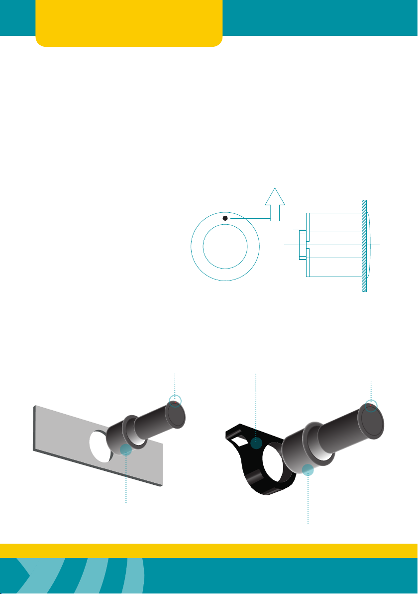
u Please mount the sensors at right angle to the ground, or slightly angled upwards.
- Note the top of the sensor head - it is marked with a small dot on the front face.
u Sensor heads should be spaced between 1m and 2m max distance, with the rst sensor
on the front corner of the vehicle all sensors should have a height of 0.6m to 1.1m.
Right Hand Drive
Left Hand Drive
Sensor 4
Sensor 3
Sensor 2
Sensor 1
Sensor 4
Sensor 3
Sensor 2
Sensor 1
5
W: EchomasterEurope.co.uk
T: +44(0)1420 487110
SIDE ALERT SENSORS I SA-US4 User Manual
Fitting Instructions (continued)
The Sensor Holes
Using the provided hole saw, drill the sensor holes. Always wear approved safety glasses when
drilling. If drilling a metal panel, coat edges of holes with Zinc galvaniser or rust inhibitor.
UP
Positioning Mark
Rubber Sleeve
Rubber Sleeve
Positioning Mark
Mounting Bracket
Mounting the Sensors
Sensors must be orientated with
‘UP’ notation mounted up
W: EchomasterEurope.co.uk
T: +44(0)1420 487110
User Manual SIDE ALERT SENSORS I SA-US4
Fitting Instructions (continued)
Connecting the Power Harness
You will need to nd and connect the following inputs
u Switched ignition live – RED
u Turn signal – Orange (labelled)
(Left or Right depending on tment),
u Footbrake – Red (labelled)
PLEASE NOTE
It is recommended that all connections are soldered.
NEVER USE A TEST LIGHT TO PROBE WIRES
Once the pickup point wires are found, connect the red wire to the Ignition, orange wire to the
appropriate turn signal wire, red wire to the footbrake wire and the black to a suitable earth point.
Running Sensors to Control Module
Many vehicles will have factory grommets to allow routing of wires from the outside to the inside
of the vehicle. If you are drilling a hole through a metal body panel to route the sensor harness
into the passenger compartment, use a suitable rubber grommet, protect any bare metal with a
zinc galvaniser or rust inhibitor and route to the control module.
Mounting the Buzzer, Warning LED & Push Button Switch
The buzzer has 3 adjustment positions: Hi, Low, and Off. You usually want to keep the buzzer on
the same side of the vehicle as the control module for ease.
The Warning LED should be placed within the drivers eye-line, it has a self adhesive backing for
mounting, route the cable behind an adjacent trim panel.
The Illuminated push button switch is designed to be panel mounted, nd a suitable mounting
position or an unused switch blank and drill a 8mm hole.
7
W: EchomasterEurope.co.uk
T: +44(0)1420 487110
SIDE ALERT SENSORS I SA-US4 User Manual
Fitting Instructions (continued)
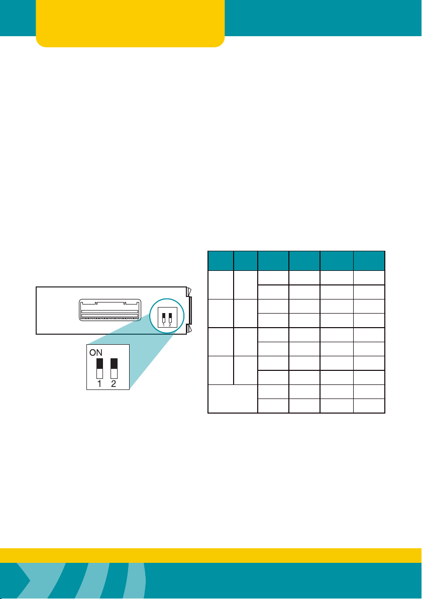
Connecting the Correct Dip Switch Conguration
1. With DIP SW1 & SW2 ON detection range is 0-0.5m the alert range for LED is 0 -2m
2. With DIP SW1 ON & SW2 OFF, detection range and alert range is set to 0 – 2m.
3. With DIP SW1 & SW2 OFF, detection range and alert range is set to 0 – 1m.
4. With DIP SW1 OFF & SW2 ON, detection range is 0 -0.5m and alert LED range is 0 – 1m.
5. With a footbrake signal present on the red wire, there will be no audible warning.
The alert LED range is 0 – 1m.
SW1 SW2 BZ/LED Zone 1
0-0.5m
Zone 2
0.5m-1m
Zone 3
1m-2m
ON ON
Buzzer ü
LED üüü
ON OFF
Buzzer üüü
LED üüü
OFF OFF
Buzzer ü ü
LED ü ü
OFF ON
Buzzer ü
LED ü ü
Brake Pedal
Input
Buzzer û û
LED ü ü
ON
Mounting Control Module
Plug in all the wires, adjust dip switches, then mount securely using the mounting bracket
provided. Finish by securing any loose and/or excess wiring. Before reassembling any panels
that might have been removed from the vehicle, test the system.

W: EchomasterEurope.co.uk
T: +44(0)1420 487110
User Manual SIDE ALERT SENSORS I SA-US4
Wiring Diagram
9
W: EchomasterEurope.co.uk
T: +44(0)1420 487110
SIDE ALERT SENSORS I SA-US4 User Manual
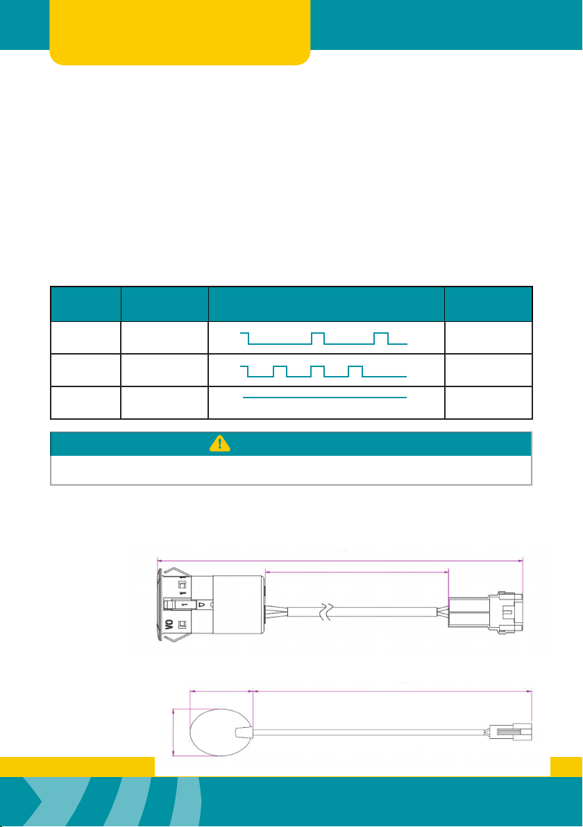
Operating Guide
Zone Distance
to object
The timing of
audio warning and LED light
Sound
code
Zone 3 100-200cm Bi....Bi
Zone 2 50-100cm Bi..Bi
Zone 1 0-50cm B...............i
100ms 100ms
ON
OFF 900ms 900ms
ON
OFF
50ms 50ms 50ms
150ms 50ms 150ms
ON
OFF
The Side Alert System will turn on with the ignition and enter standby mode this is depicted by
the LED ashing once and the Green LED on the activation switch illuminating. The Side Alert will
become fully active when an input trigger has been detected.
Once an object is detected within the range, the system will alert the driver via audible tone or
visual indicator. The Side Alert system can be temporarily deactivated by pushing the illuminated
push button switch. When deactivated the Green LED will extinguish. To reactivate the system,
press and hold the push button for 2 seconds
PLEASE NOTE
The chart reects the default zone range. Performance may be affected by the following: Heavy rain, Ice or
Snow. Please keep sensor heads clean from dirt and debris.
Dimensions
200 +/- 20mm
120 +/- 15mm
2000 +/- 30mm24.5mm
19mm
Sensor Head
LED Indicator (Visual Indication)

10 E: [email protected]
W: EchomasterEurope.co.uk
T: +44(0)1420 487110
User Manual SIDE ALERT SENSORS I SA-US4
Dimensions
100mm +/- 10mm
25mm +/- 5mm
1.0mm
20mm
R 20mm
R 20mm
R 5mm
R 6.5mm
R 5.5mm
R 2.5mm
R 1.2mm
R 1.2mm
R 0.3mm
R 2.0mm
R 6.0mm
70.0mm
56.0mm
21.0mm
R 20.0mm
Ø 25.0mm
Ø 29.5mm
Push Button (Override Switch)
Underslung Sensor Mounts
11
W: EchomasterEurope.co.uk
T: +44(0)1420 487110
SIDE ALERT SENSORS I SA-US4 User Manual
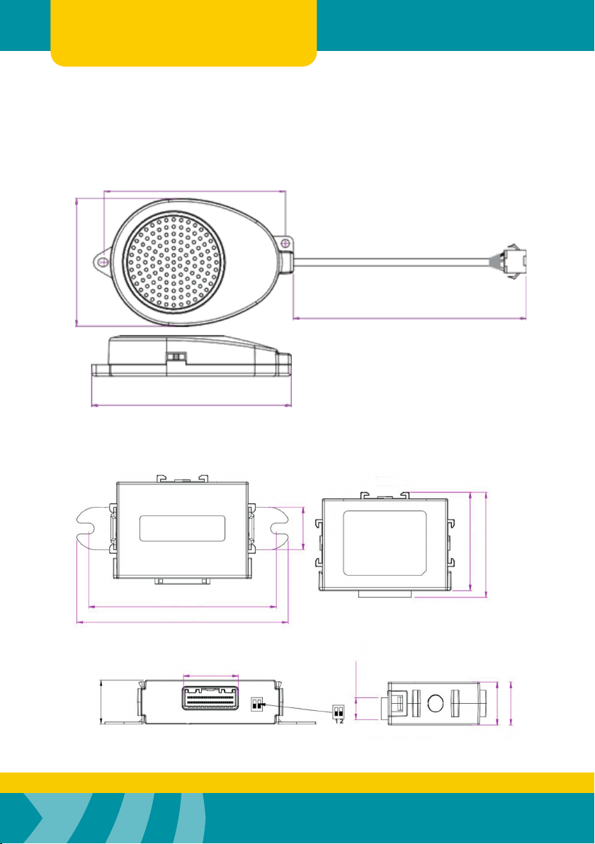
Dimensions
63.7mm
44.8mm
2000 +/- 20mm
108 +/- 0.3mm
121.6mm
32.7mm
65.2 +/- 0.2mm
61.3 +/- 0.2mm
13.3 +/1 0.1mm
26.0 +/- 0.2mm
26.0 +/- 0.2mm
Warning Buzzer (Audible Indicator)
Main Control Module

12 E: [email protected]
W: EchomasterEurope.co.uk
T: +44(0)1420 487110
User Manual SIDE ALERT SENSORS I SA-US4
Troubleshooting
PROBLEM REASON SOLUTION
System doesn’t react when a
trigger wire is activated
System is not powered up or
wrong connection of power cable
Check the power and ground
connections
Invalid connection between
speaker/display and control
module
Check the connection between
speaker/display and control
module
False Alarms Sensors rotated Note ‘UP’ marking on sensor and
adjust accordingly
Specication
SA-US4
Operating Voltage Range 16 – 28 V DC
Rated Voltage 24V DC
Rated Current 50mA (230mA max)
Operating Temperature -20C - +70C
Waterproof Grade (Sensors & Module) IP67 - Sensors
Detection Range 0-2m
Sensor Quantity 4 pcs
Hole Saw 24.5mm
Sound Range 1.0Khz

13
W: EchomasterEurope.co.uk
T: +44(0)1420 487110
SIDE ALERT SENSORS I SA-US4 User Manual
NOTES:

14 E: [email protected]
W: EchomasterEurope.co.uk
T: +44(0)1420 487110
User Manual SIDE ALERT SENSORS I SA-US4
NOTES:

15
W: EchomasterEurope.co.uk
T: +44(0)1420 487110
SIDE ALERT SENSORS I SA-US4 User Manual
NOTES:

T: +44(0)1420 487110
W: EchomasterEurope.co.uk
EchoMaster is a brand of AAMP Global
Woolmer Way, Bordon, Hampshire, GU35 9QE
aampglobal-eu.com
Other EchoMaster Pro Automobile Electronic manuals

Popular Automobile Electronic manuals by other brands


Waeco
Waeco MagicWatch MW650 Installation and operating manual

Betec
Betec CWZ2S Installation and operation

Torqeedo
Torqeedo Cruise 10 FP TorqLink Translation of the original operating instructions

Echomaster
Echomaster SSM-RBP user manual

Bully Dog
Bully Dog 40417 owner's manual

Polaroid
Polaroid C207 user guide