Eckold KRAFTFORMER KF 800 User manual
Operating Instructions
ECKOLD KRAFTFORMER
KF 800
Date of issue: 2021-09-21 English
Illustrations and measurements unbinding. Subject to change without notice.
Translation of the original instructions

22021-09-21 | ECKOLD AGKraftformer KF 800
1 General information
Dear valued customer,
You have purchased an ECKOLD product, which is characterised by its high quality and durability. We would like
to congratulate on making this purchase. is product is sure to bring you plenty of joy and provide great service
during your day-to-day work. Our customer services and sales staare always happy to help if you have any tech-
nical questions.
ECKOLD Kraformer buyback: If, one day, you no longer use your ECKOLD Kraformer, we would be willing to
buy it back. Contact us for more information.Telefon-Number 0041 81 354 12 70 or under [email protected].
1. General information
1.1 Preface
ese operating instructions are designed to familiarize the user with the machine/plant and its designated use. e
instruction manual contains important information on how to operate the machine/plant safely, properly and most
eciently. Observing these instructions helps to avoid danger , to reduce repair costs and downtimes and to increase
the reliability and life of the machine/plant.
e operating instructions must always be available wherever the machine/plant is in use. ese operating instruc-
tions must be read and applied by any person in charge of carrying out work with and on the machine/plant.
–operation, including setting up, troubleshooting in the course of work, evacuation of production waste, care and
disposal of fuels and consumables.
–maintenance (servicing, inspection, repair) and/or
–transport
In addition to the operating instructions and to the mandatory rules and regulations for accident prevention and
environmental protection in the country and place of use of the machine/plant, the generally recognized technical
rules for safe and proper working must also be observed.
1.2 Copyright
Copying as well as handing over of this document, and the use or communication of the contents thereof, is forbid-
den unless expressively authorized. Contraventions are liable to the payment of damages. All rights are reserved in
the event of the grant of a patent or the registration of a design.
© Copyright - ECKOLD AG, CH-7203 Trimmis
1.3 Validity of the operating instructions
ese operating instructions are only valid for ECKOLD Kraformer type KF 800.
1.4 CE-mark
is machine/plant has been designed, constructed and manufactured according to the EG machine guidelines and
the there to folloed alterations. Corresponding to the accordance of the machine/plant with the valid guidelines, the
CE symbol is axed to the housing of the machine and the declaration of conformity is enclosed in the delivery
contents.
K

32021-09-21 | ECKOLD AGKraftformer KF 800
1. General information
1.5 Table of contents
Chapter
Designation
Page
1 General information .............................................................................................................................. 2
1.1 Preface ............................................................................................................................................................. 2
1.2 Copyright ........................................................................................................................................................ 2
1.3 Validity of the operating instructions .......................................................................................................... 2
1.4 CE mark .......................................................................................................................................................... 2
1.5 Table of contents ............................................................................................................................................. 3
1.6 Application of the operating instructions .................................................................................................... 6
1.7 Warranty .......................................................................................................................................................... 6
2 Technical data ........................................................................................................................................ 7
2.1 Characteristic data .................................................................................................................................... ..... 7
2.2 Type plate . ....................................................................................................................................................... 7
2.3 Short Description ........................................................................................................................................... 8
2.3.1 Purpose of use ................................................................................................................................................ 8
2.3.2 Forming capacity of the Kraformer KF 800 .............................................................................................. 8
2.4 Drive ................................................................................................................................................................ 8
2.5 Mechanics ....................................................................................................................................................... 9
2.5.1 Dimensions and weight ................................................................................................................................. 9
2.5.2 Noise emissions .............................................................................................................................................. 9
2.5.3 Ram postion .................................................................................................................................................. 10
2.5.4 Working stroke ............................................................................................................................................. 10
2.6 Painting ......................................................................................................................................................... 10
2.7 Ambient temperature range ........................................................................................................................10
3 Fundamental safety instructions.......................................................................................................... 11
3.1 Warnings and symbols ................................................................................................................................ 11
3.2 Basic operation and designated use of the machine/plant ...................................................................... 12
3.3 Possible misuse ............................................................................................................................................ 13
3.4 Selecting personnel and personnel qualications ................................................................................... 13
3.5 Protective measures .................................................................................................................................... 14
3.5.1 Danger zone ................................................................................................................................................. 14
3.5.2 Required protective equipment (provided by the customer) ................................................................. 16
4 Transport / Set up ............................................................................................................................... 17
4.1 Required personnel ..................................................................................................................................... 17
4.2 Sensivity ....................................................................................................................................................... 17
4.3 Intermediate storage ................................................................................................................................... 17
4.4 Packing ......................................................................................................................................................... 17
4.5 Transport ...................................................................................................................................................... 18
4.6 Delivery contents ......................................................................................................................................... 19
4.7 Degree of Disassembly ................................................................................................................................ 19
4.8 Unpacking / Setup of the machine............................................................................................................. 20
4.8.1 Height adjustment of the machine ............................................................................................................ 21
4.8.2 Alignment of the machine ......................................................................................................................... 23
4.9 Internal transport......................................................................................................................................... 23
4.10 Workplace illumination .............................................................................................................................. 24
4.11 Disassembly ................................................................................................................................................. 24
4.12 Disposal ........................................................................................................................................................ 24

42021-09-21 | ECKOLD AGKraftformer KF 800
1. General information
Chapter
Designation
Page
5 Construction and Operation .............................................................................................................. 25
5.1 General Description .................................................................................................................................... 25
5.2 Working method ......................................................................................................................................... 25
5.3 Application areas ......................................................................................................................................... 26
5.4 Tool Overview ............................................................................................................................................. 26
5.5 Control elements ......................................................................................................................................... 27
5.5.1 Lever for single- or continuous stroke ...................................................................................................... 27
5.5.2 Foot switch for single- or continuous stroke ............................................................................................ 28
5.5.3 Safety device "EMERGENCY STOP impact button" ............................................................................... 28
6 Connection / Installation ................................................................................................................... 29
6.1 Required personnel ..................................................................................................................................... 29
6.2 Pneumatic connection ................................................................................................................................ 29
6.3 Mounting / Dismantling of the forming tools ......................................................................................... 30
7 Operation ............................................................................................................................................ 31
7.1 Required Personnel ..................................................................................................................................... 31
7.2 Setting into operation ................................................................................................................................. 31
7.3 Standard operation ...................................................................................................................................... 32
7.4 Processing of components .......................................................................................................................... 33
7.4.1 Forming Procedure ..................................................................................................................................... 34
7.5 Adjustable ram position ............................................................................................................................. 35
7.6 Adjustment of ram ...................................................................................................................................... 35
7.7 Ram stroke adjustment ............................................................................................................................... 36
8 Maintenance ........................................................................................................................................ 37
8.1 Required personnel ..................................................................................................................................... 37
8.2 General maintenance .................................................................................................................................. 37
8.3 Inspection list .............................................................................................................................................. 38
8.3.1 Mechanical components ............................................................................................................................. 39
8.3.1.1 Dirt accumulation (visual check) .............................................................................................................. 39
8.3.1.2 Damage (visual check) ................................................................................................................................ 40
8.3.1.3 Observe excessively noises ......................................................................................................................... 40
8.3.1.4 Check the tools for damage ........................................................................................................................ 40
8.3.1.5 Check the tools for secure t ...................................................................................................................... 40
8.3.1.6 Type plate and information sign existant and legible .............................................................................. 41
8.3.2 Pneumatic components .............................................................................................................................. 43
8.3.2.1 Check pneumatic connectors and cables for visible damages ................................................................ 43
8.3.2.2 Check pneumatic switch- and control elements for visible damages .................................................... 43
8.4 Maintenance ................................................................................................................................................ 44
8.4.1 General information about maintenance ................................................................................................. 44
8.4.2 Maintenance list .......................................................................................................................................... 44
8.4.3 Mechanical components ............................................................................................................................. 45
8.4.3.1 Maintenance of standard forming tools ................................................................................................... 45
8.4.3.2 Air servicing unit ........................................................................................................................................ 46
8.4.3.3 Change of battery of the ram position display ........................................................................................ 47

52021-09-21 | ECKOLD AGKraftformer KF 800
1. General information
Chapter
Designation
Page
9 Appendix ............................................................................................................................................. 49
9.1 Index of abbreviations ................................................................................................................................. 49
9.2 Directory of changes.................................................................................................................................... 49
9.3 Symbols and pictograms ............................................................................................................................ 50
9.4 Registration sheet for the operating hours................................................................................................ 51
9.5 EC declaration of conformity KF 800 ....................................................................................................... 52
10 Spare Parts Stock / Order of Spare Parts ........................................................................................... 53
10.1 Spare Parts Stock ......................................................................................................................................... 53
10.2 Order Information ...................................................................................................................................... 53
10.2.1 Example order .............................................................................................................................................. 54
10.2.2 Order form ................................................................................................................................................... 55
10.3 Customer Service Adress ............................................................................................................................ 56
11 Machine Spare Parts List .................................................................................................................... 57
11.0 Kraformer KF 800 .................................................................................................................................... 57
11.1 Housing with substructure ........................................................................................................................ 58
11.1.1 Base compl. .................................................................................................................................................. 59
11.2 Housing head ............................................................................................................................................... 60
11.3 Stroke adjustment ........................................................................................................................................ 61
11.4 Drive ............................................................................................................................................................. 62
11.5 Ram ............................................................................................................................................................... 63
11.6 Adjustable spindlescrew ............................................................................................................................. 64
11.7 Anvil ............................................................................................................................................................. 65
11.8 Tool holder ................................................................................................................................................... 66
11.9 Machine - nal equipment ......................................................................................................................... 67
11.10 Pneumatic equipment ................................................................................................................................. 68
Pneumatics scheme ............................................................................................................................. 70

62021-09-21 | ECKOLD AGKraftformer KF 800
1. General information
1.6 Application of the operating instructions
is operating instruction have been written with a view to provide information in all aspects for all persons com-
missioned to work with/on ECKOLD Kraformer KF 800.
e provided operating instructions:
• Operating instructions
• Safety directives
• Maintenance instructions
• Trouble Shooting
• Machine Spare Parts List KF 800
• Declaration of Conformity KF 800
e operating instructions have been written with a view to provide information for the operator and the mainte-
nance personnel in production. e use and observance of the operating instructions
— facilitates the proper and safe operation of the machine/plant
— makes it easy to get to know the machine/plant
— avoids interference through improper operation
— increases the reliability during use
— increases the service lifetime of the machine/plant
— reduces downtimes and repair costs
e operating instructions must always be at hand in the vicinity of the machine/plant. Operate the machine/plant
only with exact knowledge of these operating instruction.
1.7 Warranty
ECKOLD experience as well as modern production procedures and highest demands on quality guarantee a high
reliability of the machine/plant.
ECKOLD is not liable for proper functioning of the machine/plant
• when operation does not correspond to the usual application
• when applications, other than described within the terms of contract, are done
e customer has no warranty claims:
• for faulty operation
• inadequate maintenance
• the use of wrong operating materials
ECKOLD guarantee and liability conditions of the general terms of trade will not be extended in the foregoing direc-
tives. e safety regulations have to be observed unconditionally.
Use only original ECKOLD forming tools! Only ECKOLD spare parts should be used.
We reserve the right to alterations without prior notice in the course of the technical developments.
For all inquiries please state the ECKOLD contract No./Serial No.
We wish you a lot of success with the ECKOLD Kraformer type KF 800.

72021-09-21 | ECKOLD AGKraftformer KF 800
2 Technical data
2. Technical data
2.1 Characteristic data
Product data
Designation Kraformer
Type KF 800
Article-No. 021.200.2570
Serial no.
Order-No.
Year of manufactures see on the type plate
2.2 Type plate
Manufacturer data
Company ECKOLD AG
Street / No. Rheinstrasse 8
ZIP code / City CH-7203 Trimmis
Country Schweiz
Phone ++41– 81 354 12 70
Telefax ++41– 81 354 12 01
eMail [email protected]
Net www.eckold.com
Customer data
Company
Street / No.
ZIP code / City
Country
Phone
eMail

82021-09-21 | ECKOLD AGKraftformer KF 800
2. Technical data
2.3 Short Description
With its huge horizontal reach of 800 mm, the Kraformer KF 800 allows new possibilities to fabricate large-scale
sheet metal parts. e machine is air driven and released by a foot pedal, either in single or continuous stroke mode.
e single stroke function combined with the big reach is especially useful for correction jobs. Depending on the
need of forming force, the machine has two stroke settings. A digital display shows the ram position with a 0.1 mm
precision which results in a high repeatability of the forming force. e machine is adjustable in height, allowing the
operator an ergonomic working position.
2.3.2 Forming capacity of the Kraftformer KF 800
Mild steel 400 N/mm22,0 mm
Stainless steel 600 N/mm21,5 mm
Aluminium 250 N/mm22,0 mm
Copper 250 N/mm22,0 mm
Please take into account the maximum forming capacity of each tool in the accompanying tool catalogue.
2.4 Drive
Drive Compressed air cylinder
Release Pedal
Working pressure ~ 100 kN
Input pressure ~ 5,5 bar
Air requirement (QN):
- single stroke
- continuous stroke
8.0 l/stroke
~ 800 l/min.
Working stroke ~ 100 - 180 stroke/min.
2.3.1 Purpose of use
e machine ECKOLD Kraformer type KF 800 is to be used for cold forming of sheet metal and prole sections up
to the max. plate thickness mentionned under item 2.3.2.
Do not use the KF 800 Kraformer machine for any other purpose!
Original ECKOLD forming tools are available for reforming work.
Use only original ECKOLD forming tools!
e machine must NOT be used or modied for other work!
92021-09-21 | ECKOLD AGKraftformer KF 800
2.5 Mechanics
2. Technical data
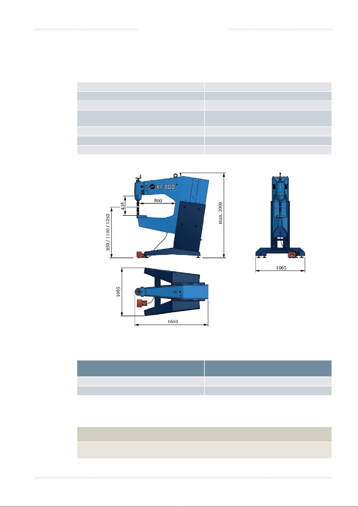
2.5.1 Dimensions and weight
Length 1610 mm
Width 1065 mm
Height max. 2000 mm
roat, horizontal
(to the front edge of tool holder) 800 mm
roat, vertical 438 mm
3 working heights with standard tools FWA/FWR 950 /1100 / 1250 mm
Weight ca. 850 kg
2.5.2 Noise emissions
Operating condition Measured A-rated sound pressure level LPA
in decibels with regard to 20 μP
Idle state 150 strokes/min (without tool) ~ 80 dB (A)
150 strokes/min - WZ FWA60K, St 300/40/30x1.5 ~ 87 dB (A)
Note: e values are determined based on the noise emission standards EN ISO 3746: 2010
and EN ISO 11202: 2010, accuracy class 3.
H IMPORTANT
• When working at 150 strokes/min or with noise emissions higher than 85 dB (A) ear
protectors must be worn, as the limit of 85 dB (A) will be exceeded.
3 working heights *)
*) Crane needed to change the height
102021-09-21 | ECKOLD AGKraftformer KF 800
2. Technical data
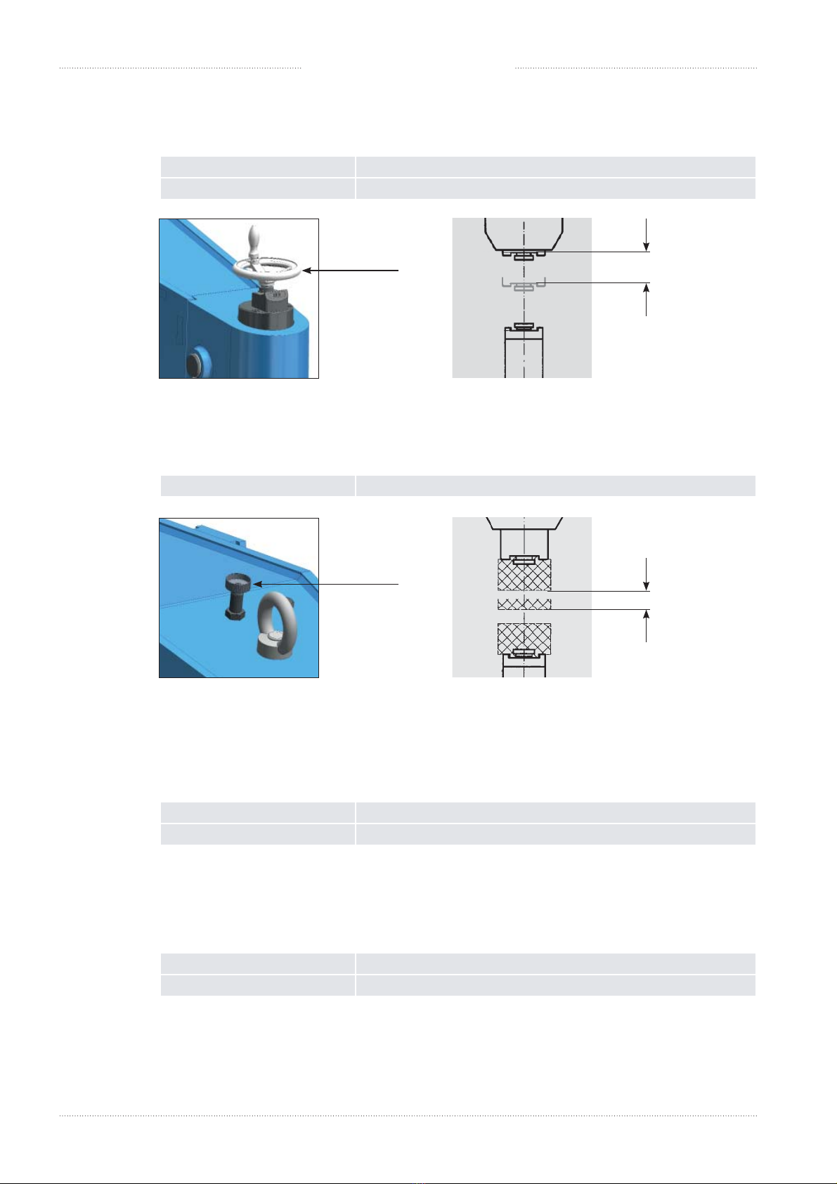
2.5.3 Ram postion
2.6 Painting
Apparatus head light blue , RAL 5012 textured coating (without silicon)
Pedestal sapphire , RAL 5003 textured coating (without silicon)
2.7 Ambient temperature range
Operating ambient temperature -20°C ..... +55°C
Storage and transport temperature -25°C ..... +70°C
Area of the ram adjustment 20 mm (by Handwheel)
Steps of the ram adjustment 0.1 mm
2.5.4 Working stroke
Adjustable stroke length 3 - 6 mm (by knurled nut )
20 mm
Handwheel
3 -6 mm
Knurled nut

112021-09-21 | ECKOLD AGKraftformer KF 800
3 Fundamental safety instructions
3. Fundamental safety instructions
3.1 Warnings and symbols
e following signs and designations are used in the manual to designate instructions of particular importance.
DANGER
WARNING
CAUTION
ATTENTION
HIndicates tips and other instructions that are particularly useful.
Indicates a potentially dangerous situation. If it is not avoided, minor
injuries might be the consequences.
—Cause: e "Cause" column contains information regarding the type of danger and its source.
—> Consequence: e "Consequences" row lists the possible consequences if the instructions
are not adhered to.
• Protective measures: e lines that are marked with a dot contain mandatory instructions that must
be strictly adhered to in order to prevent the above consequences.
Indicates a potentially dangerous situation. If it is not avoided, death or
serious injury might be the consequences..
—Cause: e "Cause" column contains information regarding the type of danger and its source.
—> Consequence: e "Consequences" row lists the possible consequences if the instructions
are not adhered to.
• Protective measures: e lines that are marked with a dot contain mandatory instructions that must
be strictly adhered to in order to prevent the above consequences.
Indicates an imminent potential danger. If no suitable measures are
taken, death or serious injuries will occur.
—Cause: e "Cause" column contains information regarding the type of danger and its source.
—> Consequence: e "Consequences" row lists the possible consequences if the instructions
are not adhered to.
• Protective measures: e lines that are marked with a dot contain mandatory instructions that must
be strictly adhered to in order to prevent the above consequences.
Indicates a potentially damaging situation. If it is not avoided, the
machine or property close to it might be damaged.
—Cause: e "Cause" column contains information regarding the type of danger and its source.
—> Consequence: e "Consequences" row lists the possible consequences if the instructions
are not adhered to.
• Protective measures: e lines that are marked with a dot contain mandatory instructions that must
be strictly adhered to in order to prevent the above consequences.

122021-09-21 | ECKOLD AGKraftformer KF 800
3. Fundamental safety instructions
3.2 Basic operation and designated use of the machine/plant
e product has the following type designation:
— KF 800 (Kraformer)
e product was designed for the following production processes:
— Reforming sheets and proles made of steel, stainless steel, aluminium or similar materials
e product is a complete machine.
e following accessoires are required for the operation:
— Tools
e machine/plant has been built in accordance with state-of-the-art standards and the recognized safety rules.
Nevertheless, its use may constitute a risk to life and limb of the user or of third parties, or cause damage to the
machine and to other material property. e machine/plant must only be used in technically perfect condition in
accordance with its designated use and the instructions set out in the operating manual, and only by safety-con-
scious persons who are fully aware of the risks involved in operating the machine/plant. Any functional disorders,
especially those aecting the safety of the machine/plant, should therefore be rectied immediately!
e ECKOLD-Kraformer KF 800 has been designed exclusively for the driving of ECKOLD-tools for the non-
cutting cold shaping of sheet metals and proles.
Applications other than those described here are not regarded as proper use. e manufacturer/supplier is not lia-
ble for damages resulting from a use in this way. e user is solely responsible for this risk. Operating the machine
within the limits of its designated use also involves observing the instructions set out in the operating manual and
complying with the inspection and maintenance directives.
Change to the normal use by the operator is forbidden!
Changes to the technical data (see chapter «Technical Data» on page 7) by the operator are forbidden!
e operating instructions must always be at hand in the vicinity of the machine/plant!
Operate the machine/plant only with exact knowledge of these operating instruction.
WARNING
— Change to the normal use by the operate
—> Risk of injury to personnel and damage to the product
• Please contact the product manufacturer if you would like to change the normal use.

132021-09-21 | ECKOLD AGKraftformer KF 800
3. Fundamental safety instructions
3.3 Possible misuse
e machine must be installed and serviced only by authorized personnel.
e machine must not be modied or altered in any way without authorization.
e operation and preventive maintenance of the machine as described in the operation manual must be performed
only by authorized and trained personnel.
As a general rule, the machine may be operated in Normal mode only if all safety features are present, properly
installed and fully functional.
e machine may be operated in other operating modes (Maintenance mode) requiring the removal of certain
safety features only while the personnel pays extra attention and if it is ensured that all safety features are properly
replaced and their function checked immediately aer the work has nished.
All problems and damages indicated by the system or detected otherwise must be reported and eliminated imme-
diately.
None of the conditions dened for the intended use, such as performance data (pressures, dimensions, weight, etc.)
or materials, may be altered.
e machine must not be operated by personnel that does not meet the requirements dened in this operation ma-
nual (see chapter 3.4 „Selecting personnel and personnel qualications“ on page 13).
Bypassing valves and other control components is prohibited
3.4 Selecting personnel and personnel qualifications
e owner of the machine (Machine) is responsible for correctly selecting personnel and qualication of personnel
for working on/with the machine.
WARNING
—Personnel who have not been trained, or who have not read the operating manual,
work on/with the product
—> Life-threatening hazards for personnel, injury hazards for personnel, Damage to the product
• Owner: Only assign personnel to work with/on the machine who have been trained
in the tasks of the relevant operating phase and/or have read the operating manual.
Provide training for your personnel for the handling of the machine so that all
instructions in the operating manual are observed. Ensure that the operating manual is
available to your personnel so that they can familiarize themselves with the content.
• Personnel: Follow all instructions listed in the operating manual.
142021-09-21 | ECKOLD AGKraftformer KF 800
3.5 Protective measures
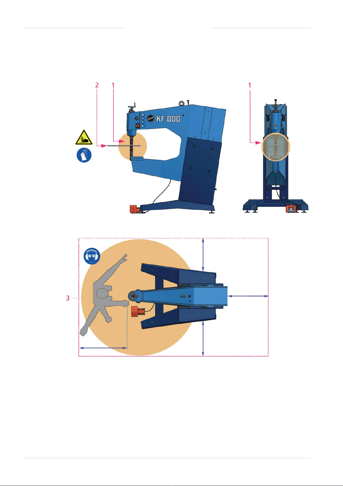
3.5.1 Danger zone
3. Fundamental safety instructions
e following areas are danger zones of the product:
1 In the working range of the ram, in particular between the tools
2 On the component (metal sheet) which is to be processed
3 In the whole access area around the product
Danger area
(Operator work station)
< 1,5 m
500 mm
500 mm
500 mm
500 mm

152021-09-21 | ECKOLD AGKraftformer KF 800
3. Fundamental safety instructions
e following dangers exist:
Danger zone 1
— Crushed upper extremities (e.g. ngers, hands, arms)
WARNING
— Reaching into the danger zone during working movements. In the working ange of the ram,
in particular between the tools
—> Crushed upper extremities (e.g. ngers, hands, arms)
• Do not reach into danger zone during working movements.
• During working movements, prevent others from reaching into the danger zone
Danger zone 2
— Cuts to upper extremities
CAUTION
—Sharp edges on component (sheet metal) which is to be processed
—> Cuts to upper extremities
• Always wear protective gloves when processing components on the Kraformer
Danger zone 3
— Hearing damage, long-term hearing loss
— Damage to vision
WARNING
—Noise during the operation of the product, in particular when components are being processed
by the product
—Flying splinters while components are being processed, particularly at high machining forces
—> Hearing damage, long-term hearing loss
—> Damage to vision, injury to personnel
• Always wear sight and hearing protection when processing components on the Kraformer.
Persons in jeopardy
Persons in jeopardy include all those who are wholly or partially located in the hazard area.
Operating personnel
Operating personnel include the following people:
— Personnel who have been assigned with operation, including charging, malfunction resolution in the work
process, disposal of production wastes, care, disposal of operating materials and auxiliary materials.
— Personnel who have been assigned with maintenance (service, inspection, repair).
— Personnel who have been assigned with transport.

162021-09-21 | ECKOLD AGKraftformer KF 800
3. Fundamental safety instructions
3.5.2 Required protective equipment (provided by the customer)
HAs the owner, it is your duty to ensure that operators are provided with the following protective
equipment in order to use the product safely.
Protective gloves
Always wear protective gloves when processing components on the Kraformer.
Sight and hearing protection
Always wear sight and hearing protection when processing components on the Kraformer.
Safety boots
Always wear safety shoes when processing components or when changing tools.

172021-09-21 | ECKOLD AGKraftformer KF 800
ATTENTION
— Carefree transport of the product (KF 800)
—> Damage to the product
• During the transport avoid condensation of water due to temperature uctuations and
vibrations due to force or careless loading and unloading.
4 Transport / Set up
4. Transport / Set up
4.1 Required personnel
Well trained and qualied personnel with the following knowledge must be used.
Training: Transport / Set up
Training and / or read of the chapter of the manual:
03 Fundamental safety instructions, 04 Transport / Set up
4.2 Sensivity
4.3 Intermediate storage
If the machine/plant is not operated immediately aer delivery, then it must be stored in a protected area dust-free
and dry. A special preservation should be undertaken, if an intermediate storage time of more than two months is
foreseen.
4.4 Packing
e way of transport is decisive for the type of packing.
• Observe the appropriate transport notes on the packing.
H IMPORTANT
• Inspect the package for visible damage and journalize them at the acceptance othe
delivery by the carrier.
• In sever damage inform immediately your transport insurance to secure your claim on
compensation for damages..
Limiting stop for
hoists
Set forklihere keep dry this side up Centre of cravity
182021-09-21 | ECKOLD AGKraftformer KF 800
4. Transport / Set up
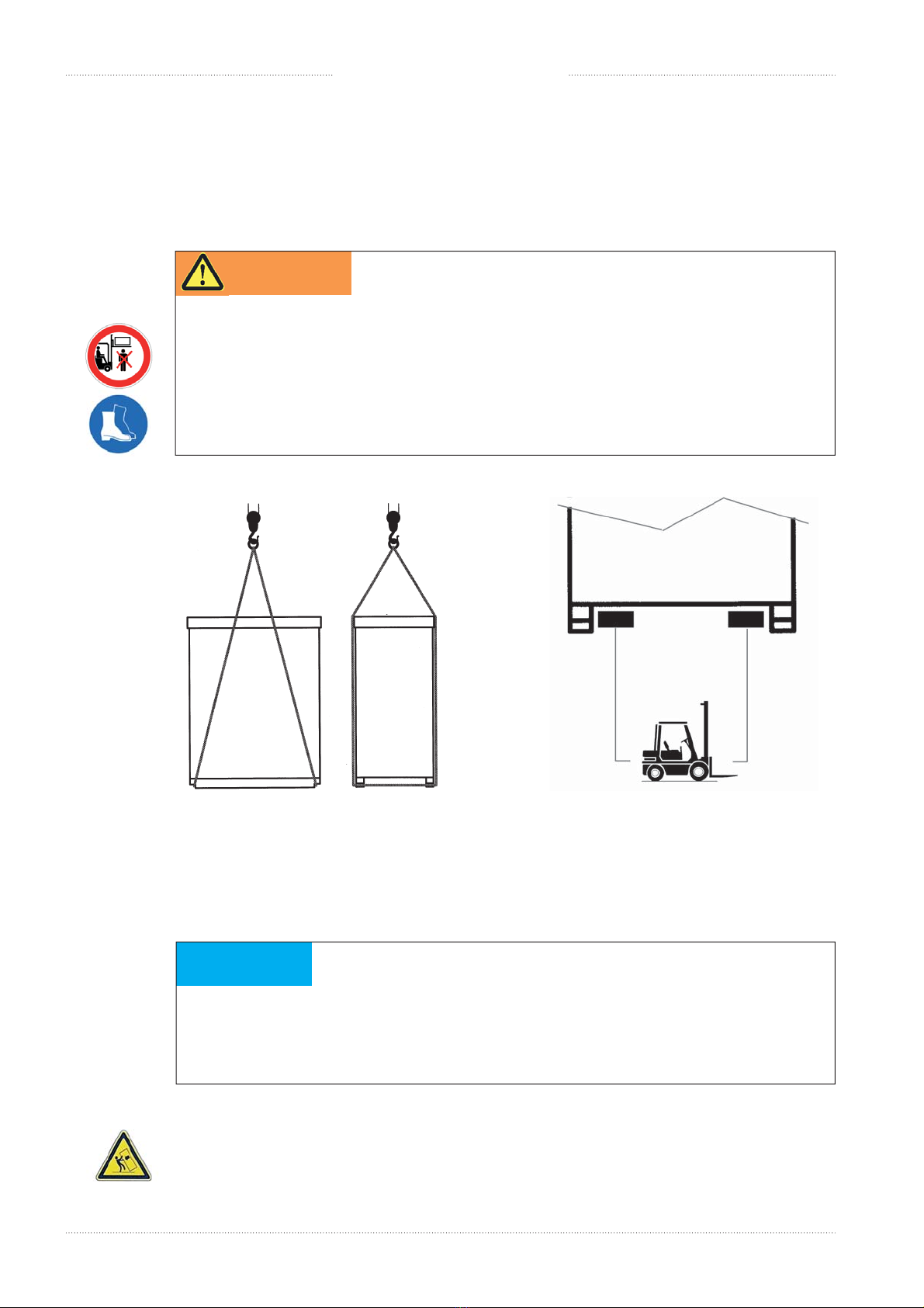
4.5 Transport
• Transport the product to its installation site using appropriate means of transportation.
• Do not lithe product with a forklior crane if the packaging is damaged.
WARNING
—Liing the product with a forkliwithout sucient carrying capacity
— Staying underneath the suspended product
—> If the product falls: Risk of death or injury to personnel, damage to the product
• Only use a forkliwith sucient carrying capacity to lithe product.
• Do not hang around near or underneath the product during transportation.
• Wear protective boots to protect your feet.
Transportation with the crane:
• Fasten the suspension ropes to the marked positions on the case.
ATTENTION
— ere is a danger of the product falling when being carried by a forkliup and down ramps.
—> Damages on the product
• Drive up and down ramps with extra caution. Only drive along routes released for for klis.
Transport with a fork litruck:
• Adjust the forks of the forklito the maximum possible width!
e centre of gravity of this unit is quite high. Danger of tilting!
Transportation with the crane Transportation with a fork litruck
approx. 920 kg

192021-09-21 | ECKOLD AGKraftformer KF 800
4. Transport / Set up
4.6 Delivery contents
H IMPORTANT
Tools are not part of the product's delivery scope. However, tools can be part of the
delivery scope of the delivery order.
• Immediately check the completeness of the delivery upon receipt. Compare the range of
delivery with the enclosed delivery documents. Possible transport damages and/or missing
parts must be reported immediately in writing.
Operating instructions
and tool catalogue
1 piece Long-Arm Hex Key
ISO 2936-L, SW14
4.7 Degree of Disassembly
e following work must be carried out in order to create operational conditions:
1. Set up of the machine (see page 20)
2. Connection / Assembly (see page 29)
• Follow all instructions in the respective sectors.
Kraformer KF 800
202021-09-21 | ECKOLD AGKraftformer KF 800
4. Transport / Set up
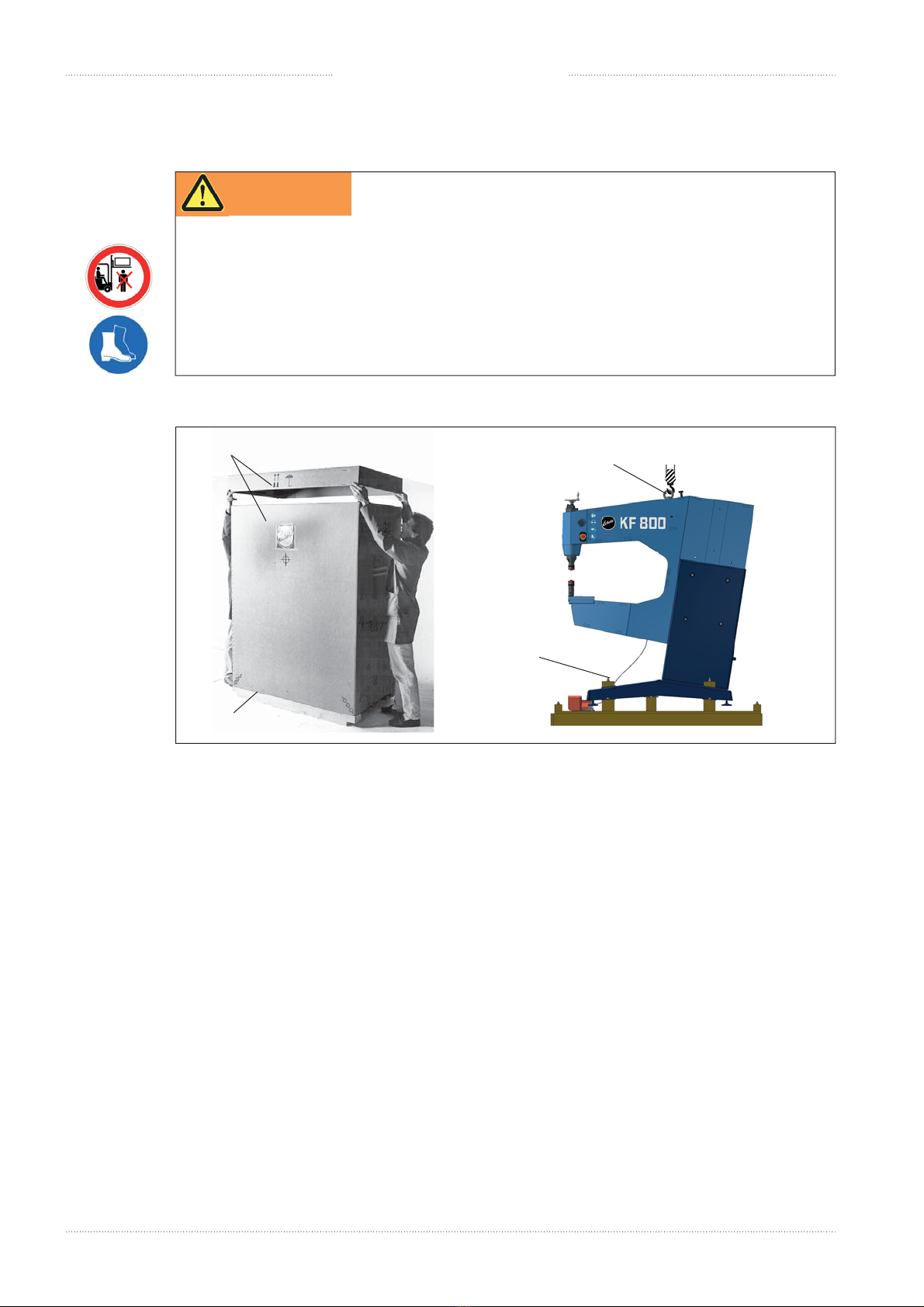
4.8 Unpacking / Setup of the machine
approx. 850 kg
Upon delivery the product is mounted on a shipping pallet.
1. Remove band and pins at the bottom edge of the box.
2. Remove the cover and the cardboard sleeve.
3. Hang the load hook in the liing screw on the top side of the machine (without liing the machine).
4. Remove the four xation nuts.
5. Lithe machine out of the sledge, using the eyebolt (3) and set it down carefully on a level industrial oor.
No anchoring of the machine is necessary!
Make sure that the product does not turn when it is lied!
Only use a crane with a rotating crane hook.
Clean the Kraformer from possible soiling such as packing residue, dust, and the similar.
WARNING
—Liing the product with a forkliwithout sucient carrying capacity
— Staying underneath the suspended product
—> If the product falls: Risk of death or injury to personnel, damage to the product
• Only use a forkliwith sucient carrying capacity to lithe product.
• Do not hang around near or underneath the product during transportation.
• Wear protective boots to protect your feet.
2
1
3
4
Table of contents
Popular Industrial Equipment manuals by other brands


Siemens
Siemens 3VL9100-4TD.0 operating instructions

Grundfos
Grundfos NBE Series Installation and operating instructions

Northline Express
Northline Express Smart-Holder instruction manual

Eaton
Eaton Char-Lynn HP30 instruction manual

ABB
ABB A140-M65 Operation manual

Salda
Salda RIS 700VE/VW EKO 3.0 Technical manual