Ecler IC3BK User manual

50-0130-0107 IC Series EN
IC Series
LOUDSPEAKERS
In-ceiling / In-wall Loudspeaker
USER MANUAL

2
INDEX
1. IMPORTANT REMARK .................................................................................... 3
2. IMPORTANT SAFETY INSTRUCTIONS .......................................................3
3. IMPORTANT NOTE .......................................................................................... 5
4. INTRODUCTION ...............................................................................................5
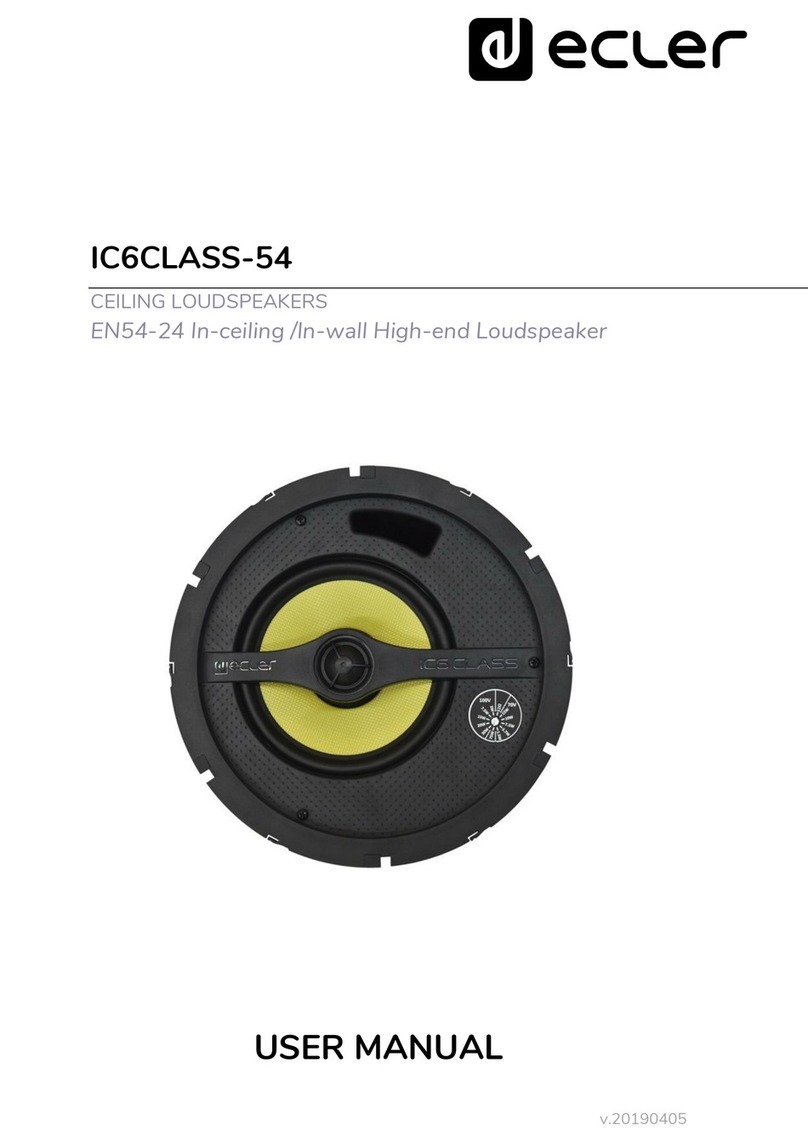
4.1 IC3............................................................................................................................5
4.2 IC6............................................................................................................................6
4.3 IC8............................................................................................................................6
5. CONNECTIONS .................................................................................................7
6. LOCATION AND ASSEMBLY.........................................................................8
7. PAINTING ...........................................................................................................9
8. TECHNICAL CHARACTERISTICS ...............................................................10

3
1. IMPORTANT REMARK
The lightning flash with arrowhead symbol, within an equilateral triangle, is
intended to alert the user to the presence of uninsulated “dangerous
voltage” within the product’s enclosure that may be of sufficient magnitude
to constitute a risk of electric shock to persons.
The exclamation point within an equilateral triangle is intended to alert the
user to the presence of important operating and maintenance (servicing)
instructions in the literature accompanying the appliance.
WARNING (If applicable): The terminals marked with symbol of “ ” may be of
sufficient magnitude to constitute a risk of electric shock. The external wiring
connected to the terminals requires installation by an instructed person or the use of
ready-made leads or cords.
WARNING: To prevent fire or shock hazard, do not expose this equipment to rain or
moisture.
WARNING: An apparatus with Class I construction shall be connected to a mains
socket-outlet with a protective earthing connection.
2. IMPORTANT SAFETY INSTRUCTIONS
1. Read these instructions.
2. Keep these instructions.
3. Heed all warnings.
4. Follow all instructions.
5. Do not use this apparatus near water.
6. Clean only with dry cloth.
7. Do not block any ventilation openings. Install in accordance with the
manufacturer’s instructions.
8. Do not install near any heat sources such as radiators, heat registers, stoves, or
other apparatus (including amplifiers) that produce heat.

4
9. Do not defeat the safety purpose of the polarized or grounding type plug. A
polarized plug has two blades with one wider than the other. A grounding
type plug has two blades and a third grounding prong. The wide blade or the
third prong are provided for your safety. If the provided plug does not fit into
your outlet, consult an electrician for replacement of the obsolete outlet.
10. Protect the power cord from being walked on or pinched particularly at the
plugs, convenience receptacles, and at the point where they exit from the
apparatus.
11. Only use attachments/accessories specified by the manufacturer.
12. Unplug the apparatus during lightening sorts or when unused for long periods
of time.
13. Refer all servicing to qualified personnel. Servicing is required when the
apparatus has been damaged in any way, such as power supply cord or plug is
damaged, liquid has been spilled or objects have fallen into the apparatus, the
apparatus has been exposed to rain or moisture, does not operate normally, or
has been dropped.
14. Disconnecting from mains: Switching off the POWER switch all the functions
and light indicators of the amplifier will be stopped, but fully disconnecting the
device from mains is done unplugging the power cord from the mains input
socket. For this reason, it always shall remain readily operable.
15. Equipment is connected to a socket-outlet with earthing connection by means
of a power cord.
16. The marking information is located at the bottom of apparatus.
17. The apparatus shall not be exposed to dripping or splashing and that no
objects filled with liquids, such as vases, shall be placed on apparatus.
NOTE: This equipment has been tested and found to comply with the limits for a
Class A digital device, pursuant to part 15 of the FCC Rules. These limits are designed
to provide reasonable protection against harmful interference when the equipment is
operated in a commercial environment. This equipment generates, uses, and can
radiate radio frequency energy and, if not installed and used in accordance with the
instruction manual, may cause harmful interference to radio communications.
Operation of this equipment in a residential area is likely to cause harmful interference
in which case the user will be required to correct the interference at his own expense.
WARNING: This product must not be discarded, under any circumstance, as
unsorted urban waste. Take to the nearest electrical and electronic waste
treatment centre.
NEEC AUDIO BARCELONA, S.L. accepts no liability for any damage that may be
caused to people, animal or objects due to failure to comply with the warnings above.
5
3. IMPORTANT NOTE
Congratulations! You are the owner of a carefully designed and manufactured
equipment. We thank you for trusting in us and choosing our IC-series speaker for
false ceilings.
In order to get the optimum operation and efficiency from this unit, it is VERY
IMPORTANT - before you plug anything - to read this manual very carefully and bear
in mind all considerations specified within it. We strongly recommend that its
maintenance be carried out by our Authorized Technical services.
All ECLER products are covered by warranty, please refer to www.ecler.com or the warranty
card included with this product for the period of validity and conditions.
4. INTRODUCTION
ECLER's line of IC speakers for false ceilings incorporates carefully selected
components in an easy-to-use design that is quick to install. They also provide
excellent sound quality for high and low thanks to our infinite speaker philosophy and
to top-performance high frequency transducer.
Because we have included a transformer in the whole series, our units are extremely
versatile and are easy to use both in applications with low impedance and in
applications running at 100V/70V. All you have to do is shift the position of the built-
in selector.
The transducers used to play low and medium frequencies are made of
polypropylene, giving them maximum, long-term stability and protecting them from
environmental factors like heat and humidity.
There are three models in the IC series: IC3, IC6 and IC8. Here, we will describe the
technical specifications of each of these models:
4.1 IC3
•1 way speaker for false ceilings
•3” polypropylene woofer
•Power: 25W RMS@8
•Sensitivity (1W/1m): 90 dB SPL
•Built-in transformer.
•External diameter: 105mm

6
•Cut out diameter: 90mm
•Available in black (RAL9004) or white (RAL9003) finish
•Installation system: spring clips (installation without tools)
4.2 IC6
•2 way speaker for false ceilings
•6” polypropylene woofer
•25mm tweeter
•Power: 40W RMS@8
•Sensitivity (1W/1m): 88 dB SPL
•Built-in transformer.
•External diameter: 204mm
•Cut out diameter: 180mm
•Available in black (RAL9005) or white (RAL9010) finish
•Installation system: Three revolving fasteners
4.3 IC8
•2 way speaker for false ceilings
•8” polypropylene woofer
•25mm tweeter
•Power: 60W RMS@8
•Sensitivity (1W/1m): 89 dB SPL
•Built-in transformer.
•External diameter: 245mm
•Cut out diameter: 222mm
•Available in white (RAL9010) finish
•Installation system: Three revolving fasteners
Note: If you use the speaker for false ceiling in 70V installations, the power for the
100V position will be half the amount shown on the switch. When used in 50V
installations, it will be a fourth of the amount.
Each model in the series comes with a protective grill that can be removed with a
hook included in the package. Be careful not to damage the speaker when removing
the grill.

7
5. CONNECTIONS
The connection terminals for models IC6 and IC8 are of the pressure clamp type for
bare cable. Once connected, just select the mode and working power of the unit with
a simple screwdriver. Always respect the polarity.
IC6 Connection plate
In the IC3 model, the connection terminals are screw-type terminal blocks. Connect
the cables as follows:
•Between "0" and "8 / 10W" terminals (negative and positive, respectively) if
your amplifier is of low impedance
•Between the "COM" terminals and "6W or 3W or 1.5W @ 100V" (negative and
positive, respectively) if your amplifier is of high impedance, thus directly
selecting a working power for the IC3 unit
The IC series are shipped from factory with the switch in 100V/70V position. If it is
connected to a low-impedance amplifier, the speaker will not be damaged, but will
perform way below its full potential. If the speaker is accidentally connected to a
100V/70V line in the 8position, it will be severely damaged.
The installation of each unit is easily carried out using the 3 rotating tabs incorporated
in models IC6 and IC8, and spring clamps in model IC3. For more information on the
installation method, see section 5 of this manual.

8
6. LOCATION AND ASSEMBLY
To install this product correctly, you must be prepared to cut circular holes where you
would like to place the speakers and have the wiring necessary for each unit.
In order to install the speakers correctly:
1. Remove the protective grating from the speaker using the hook provided in the
packaging.
2. Cut a circular hole in the false ceiling: A template for cutting/painting is
included with each unit to simplify this process. Once the unit is separated into
two parts, the outside part can be used as a template to make the hole in the
ceiling, and the inner disk can be used to protect the speaker cone if you would
like to paint the plastic another colour.
3. Use the clamps to connect the unit to the wiring of the system where the
speaker is being installed.
4. Place the speaker in the newly cut hole. Hold it in place with your hand and
push it into place, all the while making sure that the three revolving fasteners
are drawn back.
5. Press each of the three screws that are accessible from the front side of the
speaker. The speaker is now fixed in its final position.
6. Reattach the protective grille.

9
7. PAINTING
The IC series is designed to be painted, meaning it can be installed anywhere,
regardless of the aesthetic criteria of the place where it will be used.
In order to paint any of the models in the product line:
1. Remove the protective grating from the speaker using the hook provided in the
packaging.
2. Once the cut/paint template has been separated into two parts, use the inside
disk to protect the speaker cone. Place it tight on the cone. The points still on
disk after it has been separated help to fix it tight into place. The outside part
of the template can be put on the back part of the speaker, lining it up with the
plastic circle, to protect the back part from splattering if you are using spray
paint.
3. Paint the protective grating and the speaker separately. Make sure that the
small holes in the grating are not blocked by paint. Use an appropriate air-dry
paint.
4. When the paint is dry, remove the protectors. The unit is ready to be installed.

10
8. TECHNICAL CHARACTERISTICS
IC3
System
Effective frequency range1
110 Hz –20 kHz (-10dB)
Coverage angle2
147°
Power handling
10W RMS / 40W Peak
Sensitivity3
86dB (1W/1m)
Maximum SPL4
96dB continuous / 102dB peak
Power options
100V: 1,5 / 3 / 6 W and 8 ohm
70V: 0,75 / 1,5 / 3 W and 8 ohm
Recommended amplifier
20W
Transducers
Driver
3’’ woofer
Nominal impedance
8Ω
Physical
Connection type
Terminal block
Installation options
In-ceiling, in-wall
Grille material
Aluminium rust proof
Mounting system
Spring clips (installation without tools)
Finished color
Black (RAL 9004) or White (RAL 9003)
External diameter
100mm / 3.94”
Internal diameter
85mm / 3.35”
Recommended cut out diameter
85mm / 3.35”
Required depth
95mm / 3.74”
Ceiling thickness
No limit min
50mm / 1.96” max
Weight
0,5 kg. / 1.10 lb.
Pieces per box
2 units
Shipping dimensions(WxHxD)
120 x 130 x 230mm / 4.7” x 5.1” x 9.0”
Shipping weight
0,6 kg. / 4.18 lb

11
IC6
System
Effective frequency range1
75 Hz –20 kHz (-10dB)
Coverage angle2
145°
Power handling
40W RMS / 160W Peak
Sensitivity3
93dB (1W/1m)
Maximum SPL4
109dB continuous / 115dB peak
Power options
100V: 2,5 / 5 / 7,5 / 15W
70V: 1,25 / 2,5 / 3,75 / 7,5W
Recommended amplifier
80W
Transducers
Ways
2-way, full range
Low Frequency Driver
6.5’’ woofer
High Frequency Driver
1” tweeter
Nominal impedance
8Ω
Physical
Connection type
Clip-type input terminals
Installation options
In-ceiling, in-wall
Grille material
Aluminium rust proof
Mounting system
3 rotating tabs
Finished color
Black (RAL 9005) or White (RAL 9010)
External diameter
204mm / 8.03”
Internal diameter
178mm / 7.00”
Recommended cut out diameter
180mm / 7.40”
Required depth
>73mm / 2.87”
Ceiling thickness
5mm / 0.19” min
20mm / 0.78” max
Weight
1,5 kg. / 3.30 lb.
Pieces per box
2 units
Shipping dimensions(WxHxD)
240 x 250 x 220mm / 9.4” x 9.8” x 8.66”
Shipping weight
1,90 kg. / 4.18 lb.

12
IC8
System
Effective frequency range1
65 Hz - 20 kHz (-10dB)
Coverage angle2
136°
Power handling
60W RMS / 240W Peak
Sensitivity3
94dB (1W/1m)
Maximum SPL4
112dB continuous / 118dB peak
Power options
100V: 5 / 7,5 / 15 / 30W
70V: 2,5 / 3,75 / 7,5 / 15W
Recommended amplifier
120W
Transducers
Ways
2-way, full range
Low Frequency Driver
8’’ woofer
High Frequency Driver
1” tweeter
Nominal impedance
8Ω
Physical
Connection type
Clip-type input terminals
Installation options
In-ceiling, in-wall
Grille material
Aluminium rust proof
Mounting system
3 rotating tabs
Finished color
White (RAL 9010)
External diameter
245mm / 9.64”
Internal diameter
219mm / 8.62”
Recommended cut out diameter
222mm / 8.74”
Required depth
91mm / 3.58”
Ceiling thickness
5mm / 0.19” min
20mm / 0.78” max
Weight
2,3 kg. / 5.07 lb.
Pieces per box
2 units
Shipping dimensions(WxHxD)
290 x 290 x 260mm / 11.41” x 11.41” x 10.23”
Shipping weight
2,60 kg. / 5.73 lb.
110dB below the sound pressure level at specified sensitivity
26dB below the sound pressure level than that at the direction of maximum level, Max. angle
between 1 kHz and 4 kHz.
3Measured on-axis, far field and referenced to 1 meter by inverse square law. Average from
100 Hz to 10 kHz.
4Calculated from sensitivity and power handling specifications, exclusive of power
compression

13
All product characteristics are subject to variation due to production tolerances.
NEEC AUDIO BARCELONA S.L. reserves the right to make changes or improvements in the design or
manufacturing that may affect these product specifications.
For technical queries contact your supplier, distributor or complete the contact form on our website,
in Support / Technical requests.
Motors, 166‐168 08038 Barcelona ‐ Spain ‐ (+34) 932238403 | [email protected] | www.ecler.com
This manual suits for next models
5
Table of contents
Other Ecler Speakers manuals

Ecler
Ecler IW103 User manual

Ecler
Ecler TRAIL103 User manual

Ecler
Ecler IC6CLASSI User manual

Ecler
Ecler ARQISi Series User manual

Ecler
Ecler ePHS20T User manual

Ecler
Ecler TRAIL103 User manual

Ecler
Ecler eAM106WH User manual

Ecler
Ecler ARQSB10SATB User guide

Ecler
Ecler AUDEO103 User manual

Ecler
Ecler DACORD SB210 User manual

Ecler
Ecler IW103 User manual

Ecler
Ecler eAMBIT103 User manual

Ecler
Ecler LABI1 Series User manual

Ecler
Ecler ARQIS 108BK User manual

Ecler
Ecler DROP6 User manual

Ecler
Ecler PHS20T User manual

Ecler
Ecler ARQIS Series User manual

Ecler
Ecler ARQISi SB6TiWH User manual

Ecler
Ecler AUDEOSB110P User manual

Ecler
Ecler ARQIS105 User manual