EcoFasten Clickfit User manual

RAPID
INSTALLATION,
HIGH-QUALITY SOLAR
MOUNTING SYSTEM
FOR SHINGLE AND
TILE ROOFS

2
REV DATE: 07/16/2020VERSION: 2.0
Subject Page #
Introduction 3
Product Description 4
Ratings 5
System Components 6
Required Tools 7
Array Layout 8
Installing ClickFit 9
Flashing and L feet 10
Installing Tile Hooks 11
Tile Hook Sub-Flashing 12
Installing the Rail 13
Module Installation 14 - 17
Bonding and Grounding 18 - 19
MLPE Clip Intallation 20
UL2703 Certied Modules 21-29
Clamp Tables 30
TABLE OF CONTENTS

3
REV DATE: 07/16/2020VERSION: 2.0
1.0 Introduction
This manual describes the installation of the ClickFit mounting system for photovoltaic modules on steep-
slope roofs. Described within are details for composition shingle and tile, attachments for ClickFit for other
roof types are available at www.EcoFastenSolar.com.
All installation manuals are available for download at www.EcoFastenSolar.com.
2.0 General Installation Conditions
2.1 General
Failure to observe the requirements in this document can lead to the exclusion of all guarantees and
product liability. EcoFasten Solar reserves the right to amend this document without prior notice.
2.2 Stability and Condition of the Roof
The roof must be in good condition and strong enough to support the weight of the modules, including the
additional equipment, wind and snow loads. When in doubt, consult with the engineer of record, and/or the
local building inspector.
2.3 Application Range of ClickFit
• Refer to Compatibility module list on page 21.
• Please refer to the Ecofasten ClickFit span tables for system structural certication
and allowable spans.
2.4 Warranty
Guarantee according to the warranty conditions and general terms and conditions of EcoFasten Solar. These
conditions can be found on the website at www.EcoFastenSolar.com.
2.5 Liability
EcoFasten Solar cannot accept any liability whatsoever for damage or injury caused by not taking adequate
safety precautions or (accurately) following the instructions given, or resulting from negligence during the
installation of the product and any corresponding accessories specied in this document.
*Printing errors reserved
INTRODUCTION

4
REV DATE: 07/16/2020VERSION: 2.0
The ClickFit mounting system consists of patented adjustable tile hooks and L feet, rails,
and the installation materials required for the mounting of photovoltaic modules on
composition shingle or tile roofs. For simplicity, tile hooks and L feet will be referred to as
“attachments”.
3.1 Attaching to the Roof
The attachments are fastened to the rafters. Attachments are height-adjustable to level
the system on uneven roof surfaces.
3.2 Attaching the Rail
The rail assembles to the attachments with a click-connector, or Clicker. The rail simply
clicks into place without the use of any tools.
3.3 Attaching the modules
The modules are attached to the rails by means of mid clamps and end clamps.
Installer must review the module manufacturer’s installation manual to conrm
compliance to the warranty terms and conditions.
PRODUCT DESCRIPTION

5
REV DATE: 07/16/2020VERSION: 2.0
Torque Specications
UL 2703 Marking Example:
Fire Rating** Class A System Fire Rating
Max System Voltage 1500 VDC
Max Fuse Rating 30A
Certication Conforms to UL STD 2703
Warranty 20 Year Material and Workmanship
UL 2703 Markings Product listing label is located on the rail end-caps
Roof Pitch 2:12 – 12:12
UL 2703 Allowable Design Load Rating 10 psf downward, 5 psf upward, and 5 psf lateral
Max Module Size 24 sqft
Module Orientation: Portrait or Landscape
Component Torque (in-lb) Notes
Lag Screw N/A Fully Seat. Use visual indicator of the black EPDM ring around the bonded
washer for torquing.
Mid-Clamp 144
End-Clamp 96
Rail Clicker Leveling Bolt 142 Pre-torqued upon delivery. Applies to Tile Hook and L-Foot/Clicker
Hook Height Bolt N/A Lightly clamp hook to ush with top of next tile row
Ground Lug N/A Refer to specic ground lug manufacturer’s installation manual
MLPE Clip 144
MLPE Mount 144
CLICKFIT
SYSTEM
MFG ID CODE: XXX-MM-YYYY
Conforms to UL STD 2703
1234567
TM
**Class A System re rating with Type 1 & 2 PV modules. Any module-to-roof gap is permitted, with no skirt required. This
rating is applicable with any roof attachment.
NOTE: Mid Clamp, MLPE Clip, and MLPE Bracket have been evaluated for multiple use, position independent.
RATINGS

6
REV DATE: 07/16/2020VERSION: 2.0
1) ClickFit Rail
1500033 (2130mm)
1500034 (3166mm)
1500035 (4202mm)
8) MLPE Clip (RockIt Clip 2.0)
9) Module Jumper
1500028
7) MLPE Mount
1510057
2) Rail Splice
1008061
4) CF End Clamp
See Section 10
5) CF End Cap
1510041 (Black)
1510042 (Grey)
3) CF Tile Hook and L foot
1500005 - Tile Hook
1500004 - L foot
6) CF Mid Clamp
See Section 10
SYSTEM COMPONENTS
7
REV DATE: 07/16/2020VERSION: 2.0
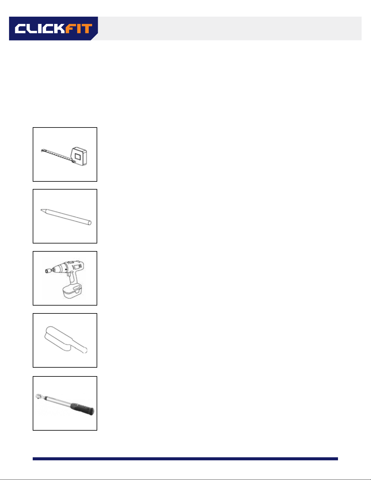
Checklist of tools and accessories
Note: *Proper PPE shall be worn at all times*
Tape measure
Roof crayon or chalk (a chalk line can be helpful as well)
Cordless drill with torque adjustment and the following bits:
• 1/2” Hex socket
• 1/4” diameter drill bit. (Drilling length no less than lag bolt depth)
Brush for clearing debris from roof surface. Hint: Leaf blowers
work well to remove any leftover moisture prior to installation.
Torque wrench capable of 0-150 in-lbs
REQUIRED TOOLS

8
REV DATE: 07/16/2020VERSION: 2.0
• Refer to span tables, local jurisdiction, or engineer of record specications when determining setbacks
from roof edges, attachment spans, etc.
• Mark the perimeter and corners of the array on the roof surface.
*Add 3/4” to account for the gap between modules in each direction*
• Draw or snap chalk lines where the rails will be installed,(refer to module manufacturer specs to
determine allowable mounting locations).
• Locate rafters within the area of the array. It may be necessary to shift the array East or West on the roof
in order to fall within the rail cantilever specs (l/3) of span).
• Stagger rafters every row if required by the local jurisdiction, engineer of record, or company policy.
ARRAY LAYOUT

9
REV DATE: 07/16/2020VERSION: 2.0
Pre-installing rail splices
1. Determine the number of rails required per row of modules.
2. Insert a rail splice into one rail. *Do not push it past the center bump.*
3. Slide the next rail onto the rail splice until the two rail ends meet.
4. Repeat steps 2 and 3 until the desired length is achieved. *This is usually easiest to do from the
ground.*
INSTALLING CLICKFIT

10
REV DATE: 07/16/2020VERSION: 2.0
Installation of flashing and L feet
• ClickFit for comp shingle roofs uses EcoFasten Solar’s GFl watertight ashing system
• Other roof types may use dierent EcoFasten Solar attachments, see www.EcoFastenSolar.com for more
information.
Installation Steps:
1. Locate rafter lines from section 5.2.
2. Drill l/4” pilot holes at all attachment points and back ll using roof-compatible sealant.
3. Separate shingles where ashing is to be installed. Insert the ashing so the top portion is under the
next row of shingles North. Ensure the ashing is pushed to the third-course of shingle to prevent water
inltration through the vertical joints between shingles.
4. Align GFl ashing hole with pilot hole. Insert the lag bolt with pre-installed bonded washer through the L
foot and EPDM grommet. Tighten the lag bolt until a ring of EPDM is visible around the circumference of
the bonded washer.
Tighten the lag until fully seated. The EPDM Ring visual indicator is the most eective way to ensure a watertight seal.
*Note the orientation of the L foot and Clicker. The two
Clicker “arms” should be facing downslope*
FLASHING AND L FEET

11
REV DATE: 07/16/2020VERSION: 2.0
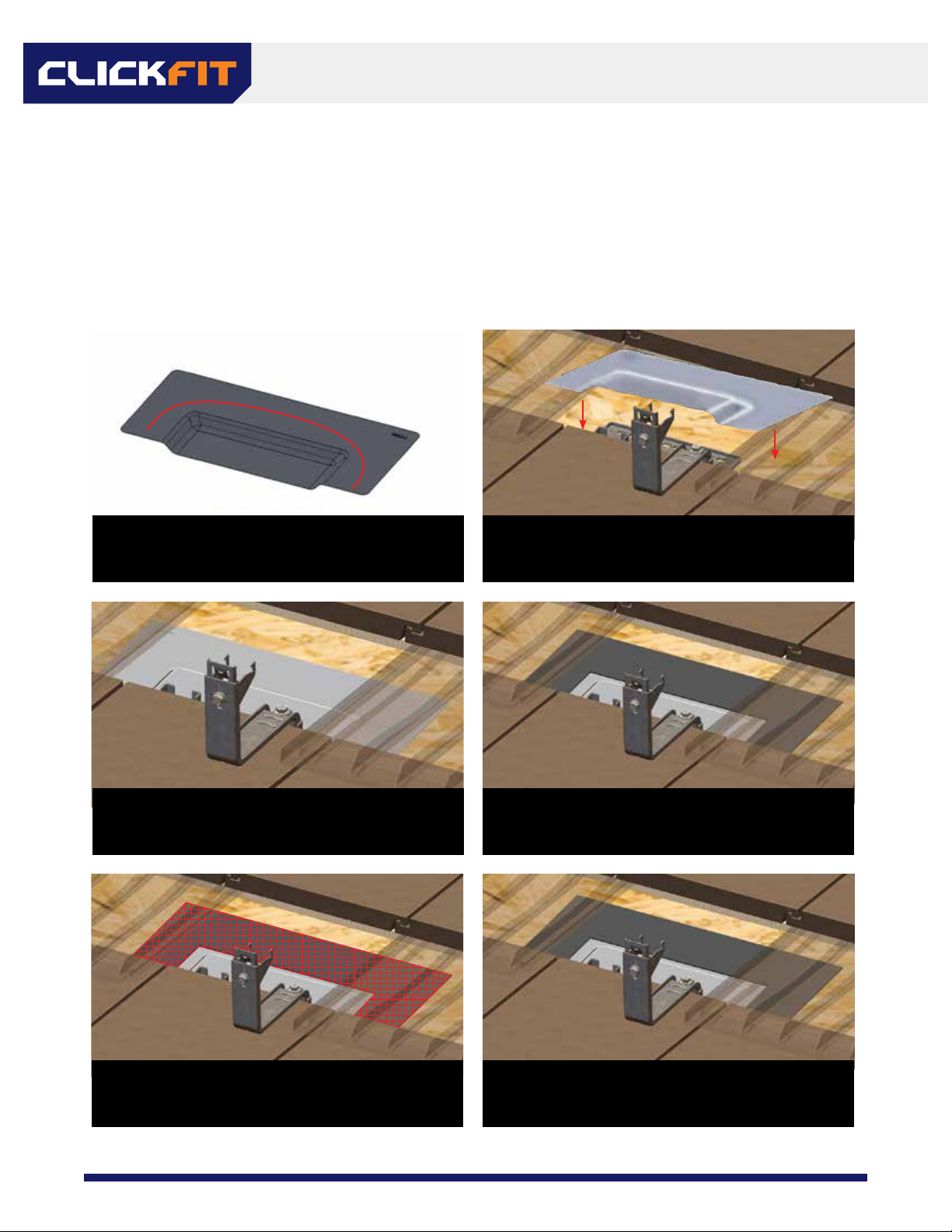
1. Locate rafters on the roof, mark the tiles to be removed. Hint: In some cases rafter tails are visible at the
eaves of the roof, making it easy to nd the rough location of the rafters. In other cases, the fascia board
may have nail heads visible where it was attached to the rafters. In the worst-case a row of tiles may
need to be moved to determine the rafter locations.
2. Slide the tile at the desired location upward to expose the roof sub surface. If the tile is to be notched,
or if using a replacement ashing, remove it entirely. Clean the sub surface with a brush to remove any
debris that could aect the sealing.
3. Locate the rafter center and mark it.
4. Place the tile hook with the hook itself in the valley of the next tile below. Drill one l/4” pilot hole in the
rafter center, taking care to keep the hook in the valley of the tile below. Backll this hole with a roof-
compatible sealant. For at tiles, try to avoid having the hook land directly under a joint between tiles,
this will create a larger gap or more notching than necessary.
5. Install one 5/16” x 4” lag screw on the row of holes closest to the tile hook arm. If possible, install the
screw in one of the three holes directly next to the arm. If the lag screw must be installed in one of the
seven holes furthest from the arm (denoted by the red rectangle below), install three deck screws in the
pattern shown by the green circles below.
6. Adjust the height of the tile hook as necessary using the bolt shown in the fourth image.
7. Flash the surrounding area and lag screw head with roof-compatible sealant as necessary. Refer to Tile
Hook Subashing Installation guide on the next page.
8. Replace the tile that was moved and/or removed, or install the tile replacement ashing. If it is to be
notched, mark the tile for notching. Notching can be done with a grinding wheel or by using a chisel.
5.
6.
INSTALLING TILE HOOKS
12
REV DATE: 07/16/2020VERSION: 2.0
CLICKFIT TILE HOOK SUB-FLASHING INSTALLATION STEPS:
Tools Required: Caulking gun, roong mastic applicator
Materials Required: Roong mastic, reinforcing fabric, roof sealant
Lower the sub-ashing over the tile hook base. It may
be necessary to move adjacent tiles to easily lower the
sub-ashing onto the roof deck.
Apply a continuous line of the roong
manufacturer’s approved sealant on the
underside of the ClickFit tile hook sub-ashing
to form a U-shape around the raised edges.
EcoFasten recommends following the TRI guidelines
three-course sealing method. Start the three-course
sealing method by applying a layer of roong mastic
over the edges of the tile hook sub-ashing.
Place the sub-ashing over the base of the tile hook so
the ashing covers the entire base.
Apply a nal layer of mastic to completely cover
the reinforcing fabric. The ashing is now installed
and sealed.
Place strips of reinforcing fabric over mastic to
cover approximately 2” from the edge of the
sub-ashing in both directions. Place strips on
the side rst, then the top edge.
Jan-2020, Rev 1
TILE HOOK SUB-FLASHING
13
REV DATE: 07/16/2020VERSION: 2.0
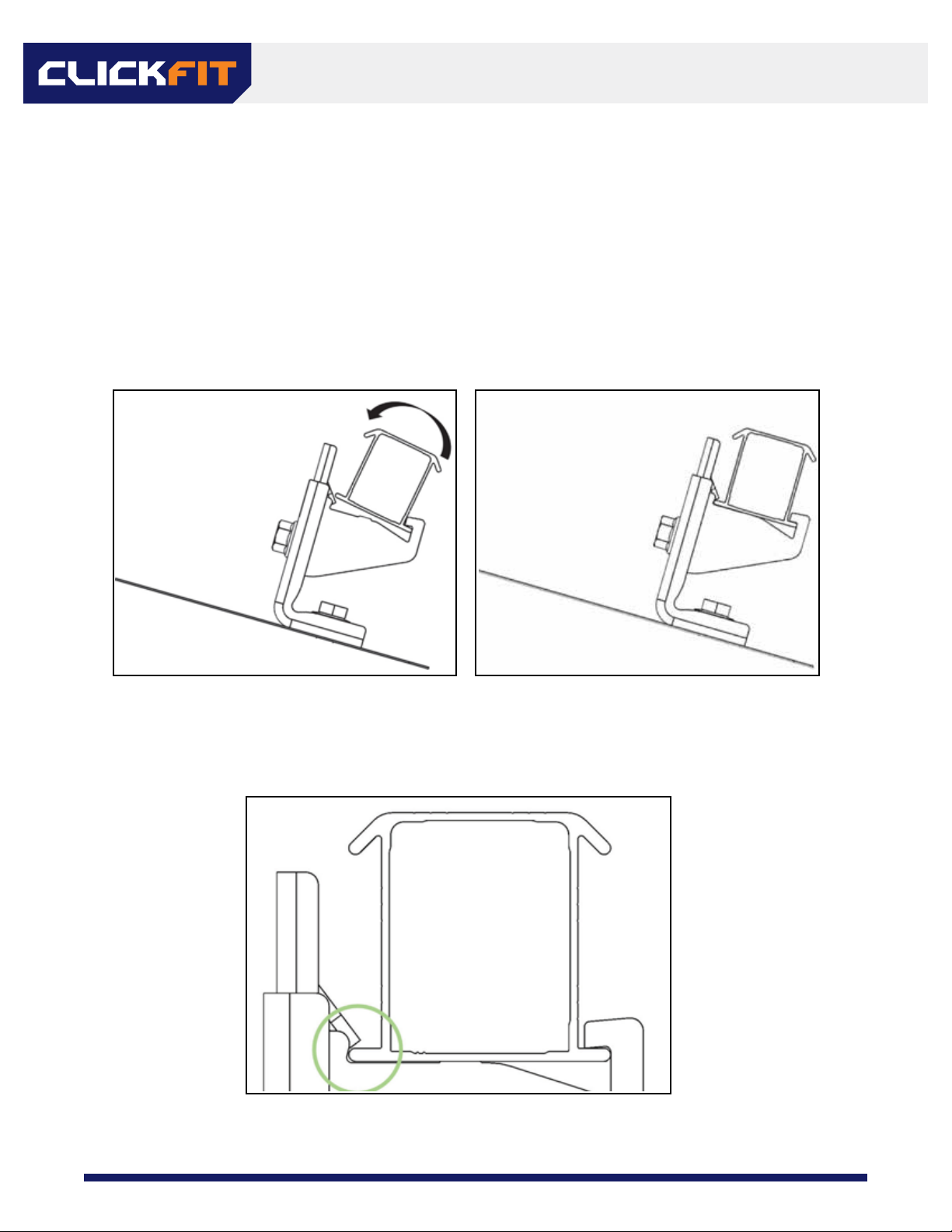
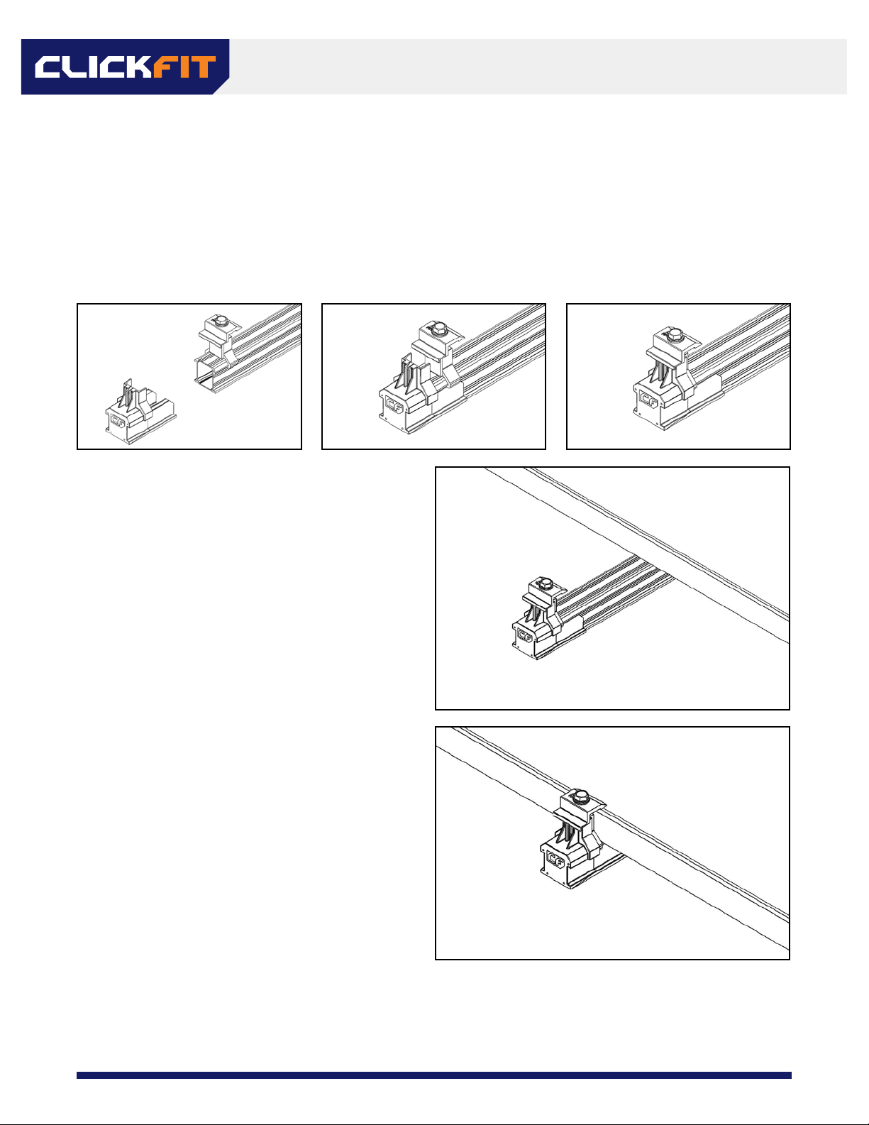
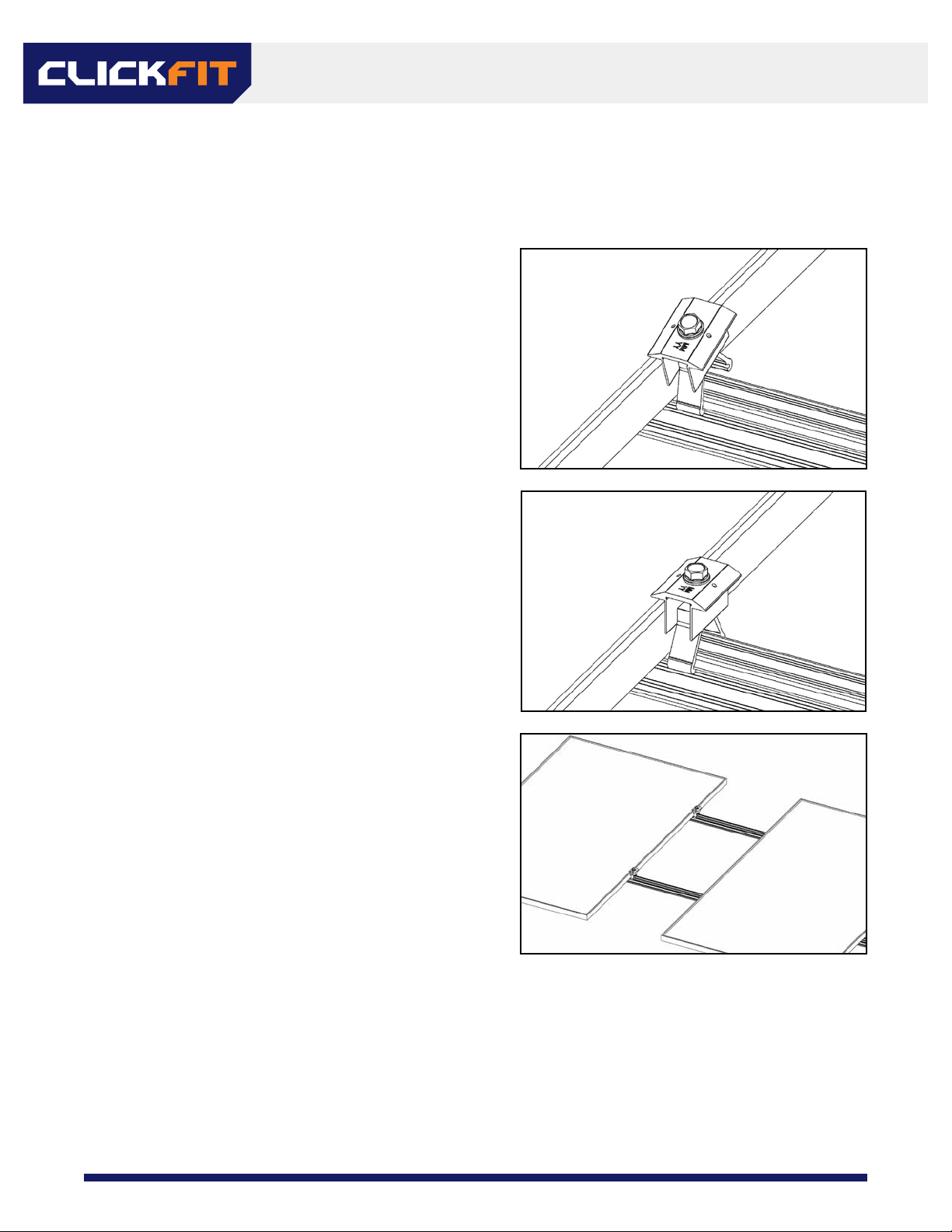
1. Place the rail in the Clickers.
2. Ensure the rails extend a minimum of 2” past the last attachments in each row and that each rail is
aligned with the next row North and/or South.
3. Roll the rail into each Clicker, an audible “click” should be heard. If attachments are extremely misaligned
it may be necessary to loosen the leveling bolt, snap the Clicker onto the rail, then re-tighten the leveling
bolt to 142 in-lbs.
4. Level the rail if necessary by loosening the bolt attaching the Clicker to the L foot or tile hook.
*Ensure the tab on the Clicker is aligned with the rail edge as shown below*
INSTALLING THE RAIL
14
REV DATE: 07/16/2020VERSION: 2.0
1. Install the end clamps on each rail on whatever end you are starting with.
• Snap the end clamp onto the rail.
• Slide the end cap onto the rail.
• Turn the leg of the end clamp around the cap.
2. Place the module on the rail.
*Ensure module junction box is up-slope.*
3. Slide the module to the end clamp and align
it with the array corners. Tighten the end
clamp to 96 in-lb.
MODULE INSTALLATION
15
REV DATE: 07/16/2020VERSION: 2.0
6.6 Installing additional modules on the rail
1. Click a mid clamp onto each rail.
2. Slide the mid clamps until they are ush with the
side of the existing module.
3. Place and slide the next module rmly against
the mid clamps. Align the bottom edges of the
modules. Tighten mid clamps to 144 in-lb.
MODULE INSTALLATION

16
REV DATE: 07/16/2020VERSION: 2.0
6.7 INSTALLING END CLAMPS AT THE END OF A ROW
1. Install the last mid clamps in the row.
2. Measure the rails from the last mid clamp to the module width plus l”.
3. Cut the rails at this mark. There is some adjustment in the end cap/clamp so it does not need to be a
perfect cut.
4. Install end clamps and end caps, tighten to 96 in-lb
Alternative method:
1. Install the last module in the row, tighten the mid clamps.
2. Using a circular saw with a metal blade, or carefully with a reciprocating saw, cut the rail approximately
l” past the edge of the last module.
3. Install end clamps and end caps, tighten to 96 in-lb
MODULE INSTALLATION
17
REV DATE: 07/16/2020VERSION: 2.0
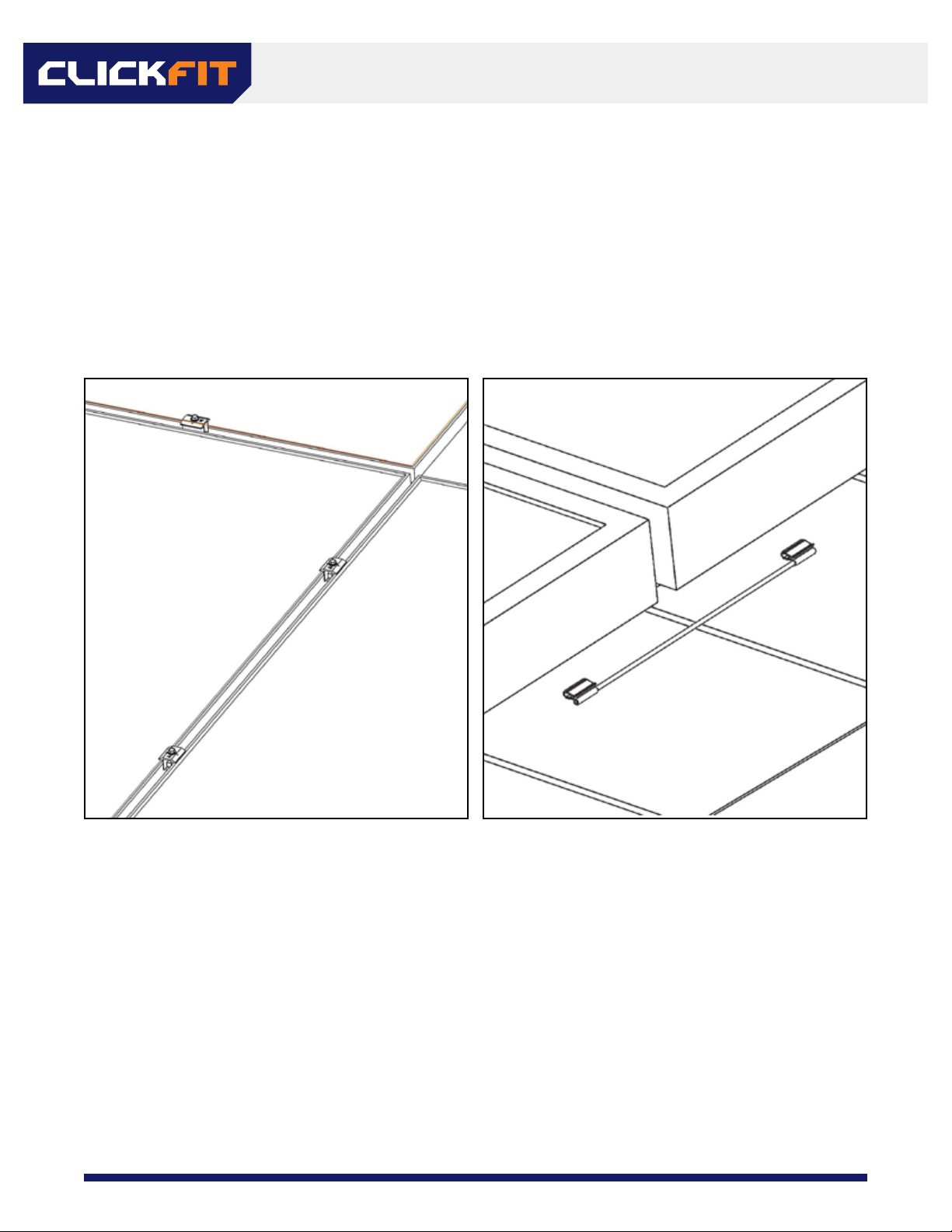
6.8 Installing additional rows of modules
1. Place the rst module of the next row against the end clamps.
2. Temporarily place a mid clamp in the N-S gap between rows of modules, slide the modules up to the
mid clamp as shown below.
3. Once the modules are aligned tighten the end clamps.
4. Install Dynobond clip on the bottom lip of the module frames to bond rows together.
5. Repeat steps 6.5-6.7 until the array is complete.
MODULE INSTALLATION

18
REV DATE: 07/16/2020VERSION: 2.0
Bonding Paths
All bond paths are carried either module-to-module through the mid clamp, or module-to- module through
the module jumper shown below (bond paths shown in green):
1 ground lug per
continuous array
BONDING AND GROUNDING
19
REV DATE: 07/16/2020VERSION: 2.0
Install ground lug on the module per ground lug and module manufacturer’s instructions
NECESSARY COMPONENTS:
On of the following ground lugs (or any UL 2703 compliant ground lug):
• BurndyCL50-1TN Ground Lug (UL 2703 - E3514343 / UL 467-E9999)
• ILSCO SGB-4 Ground Lug (UL 2703 - E354420 I UL 467 - E34440)
• ILSCOGBL-40BT(UL2703 - E354420 I UL467 - E34440l
• ILSCO GBL-4DBTH (UL 2703 - E354420 / UL 467 - E34440)
• ILSCO GBL-455 (UL 2703 - E354420 I UL 467 - E34440)
This system needs to be grounded in accordance with the National Electrical Code, ANSI/NFPA 70.
*Copper wire should not come in direct contact with aluminum at any point on the array*
7.3 MLPE Clip Installation (Optional)
7.2 Grounding
GROUNDING LUG INSTALL
INSTALL MLPE CLIP ACCESSORY
• Determine mounting location of the MLPE and MLPE Clip
on the module frame. Take care not to block drainage
holes on the frame.
• Push the nut/bolt of the MLPE Clip so the carriage bolt
head is furthest away from the stainless plate.
• Slide the bolt shaft into the slot on the MLPE mounting
ange.
• Place the assembly onto the module ange, MLPE
mounting ange on the far face (upper side) of the
module frame ange, stainless plate on the closer face
(bottom side) of the module frame ange.
• Hold the carriage bolt into the MLPE mounting ange
slot with your nger, this will keep the carriage bolt from
spinning in the slot. Tighten the nut to 144 in-lbs using a
1/2” hex socket.
MLPE CLIP IS COMPATIBLE WITH:
• Enphase Products: M250-72, 250-60, M215-60, C250-72, S230, S280, IQ
6, IQ 6+, IQ, IQ7, IQ 7A, IQ 7+, IQ 7X, Q Aggregator
• SolarEdge Products: P300, P320, P340, P370, P400, P405, P485, P505,
P600, P700, P730, P800p, P800s, P850, P860
• See page 21 for compatible module list with MLPE Clip
BONDING AND GROUNDING

20
REV DATE: 07/16/2020VERSION: 2.0
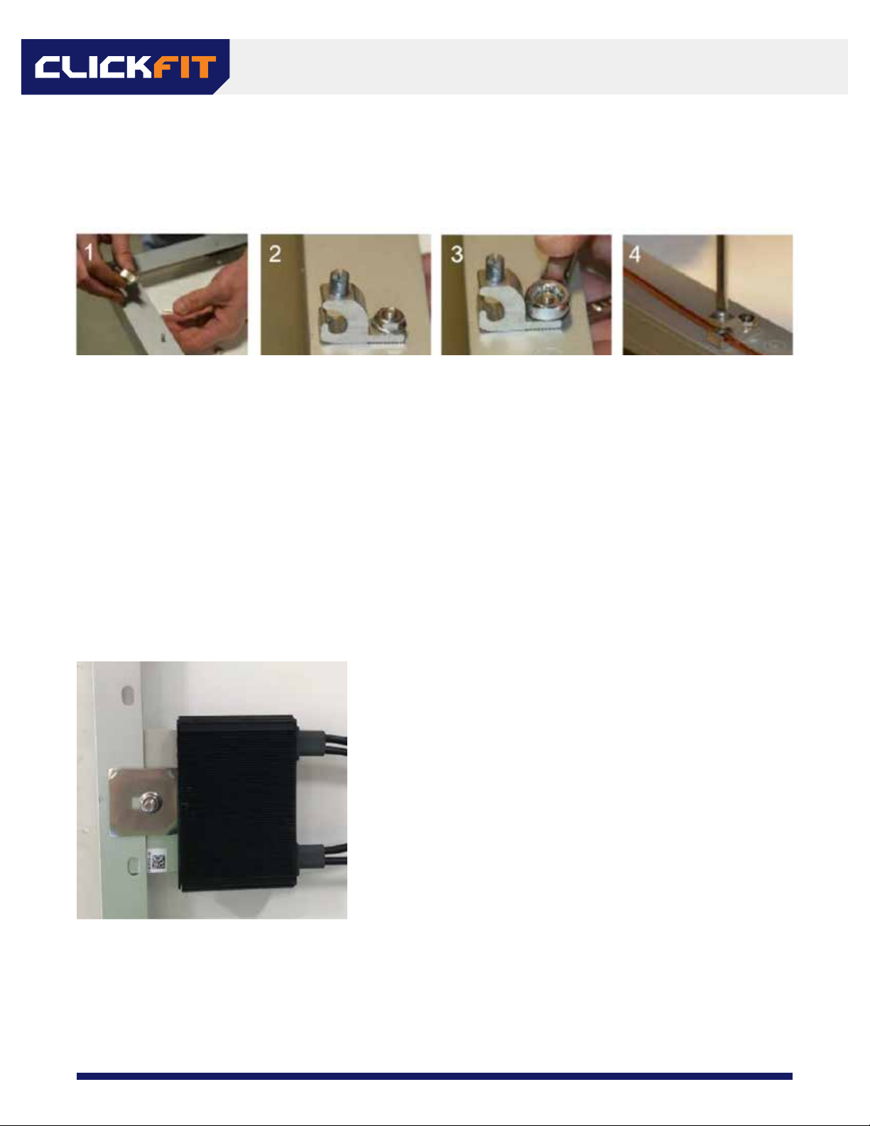
MLPE MOUNT INTALLATION
Lower the MLPE Mount to the rail
Set the MLPE Mount ush with the top of the rail
Tighten the bolt to 144 in-lbs
Tilt and hook the mount around
the top “dog ear” of the rail
Slide the microinverter ange between the
MLPE Mount and the serrated bolt ange
Repeat this process for all other microinverter
and/or optimizer installations
MLPE MOUNT IS COMPATIBLE WITH:
Enphase Products: M250-72, 250-60, M215-60, C250-72, S230, S280, IQ 6, IQ 6+, IQ, IQ7, IQ 7A, IQ 7+, IQ 7X, Q Aggregator
SolarEdge Products: P300, P320, P340, P370, P400, P405, P485, P505, P600, P700, P730, P800p, P800s, P850, P860
Other manuals for Clickfit
1
Table of contents
Popular Inverter manuals by other brands


Manitou Systems
Manitou Systems PB-3 SERIES owner's manual

Kaco
Kaco blueplanet 50.0 TL3 Basic operation instruction

Western Co
Western Co W-HPT-3000 Quick installation guide

Huawei
Huawei SUN2000-196KTL-H0 quick guide

TRU Components
TRU Components 1570889 operating instructions

Ingersoll-Rand
Ingersoll-Rand 4TXK2309A1 installation manual