Ecolab Advanced Laundry User manual

Advanced Laundry Control System
Installation & Operation Manual
Retain this manual for installation, operation,
programming, and servicing information.
37179/0404/0707 Copyright Ecolab Inc. 2007 9258-2021
Advanced Laundry Control System Installation & Operation Manual 1

Advanced Laundry Control System Installation & Operation Manual 2
This page intentionally left blank.

Advanced Laundry Control System Installation & Operation Manual 3
Contents
1.0 System Introduction ............................................................................................. 5
1.1 Preface ............................................................................................................. 5
1.2 System Features .............................................................................................. 6
1.3 Principle of Operation ....................................................................................... 6
1.4 Controller Description ....................................................................................... 9
2.0 Specifications ..................................................................................................... 10
2.1 Pump Module Assembly ................................................................................. 10
2.2 Controller ........................................................................................................ 10
2.3 Machine Interface ........................................................................................... 11
2.4 Utilities ............................................................................................................ 11
2.4.1 Electrical Supply...................................................................................... 11
2.5 Communication Cables................................................................................... 11
2.6 General and Environmental Specifications ..................................................... 12
3.0 Installation .......................................................................................................... 12
3.1 Preplanning the Installation ............................................................................ 12
3.2 Materials Ordered Separately......................................................................... 12
3.3 Pump Module Installation ............................................................................... 13
3.4 Controller Installation...................................................................................... 14
3.4.1 Mounting on Vertical Surfaces (Preferred) .............................................. 14
3.4.2 Mounting on Horizontal Surfaces ............................................................ 14
3.4.3 Mounting to Machine Wall ....................................................................... 15
3.5 Machine Interface Installation ......................................................................... 16
3.5.1 Mounting Machine Interface .................................................................... 16
3.5.2 Signal Voltage ......................................................................................... 16
3.5.3 Supply Trigger Wiring .............................................................................. 16
3.5.4 Chart Stop Wiring .................................................................................... 17
3.5.5 Event Mode Wiring .................................................................................. 17
3.5.6 MicroMode Signal Wiring......................................................................... 18
3.6 Communication Cables................................................................................... 18
3.7 Supply Tubing Installation............................................................................... 18
4.0 Programming...................................................................................................... 19
4.1 General Information........................................................................................ 19
4.1.1 Definitions and Conventions.................................................................... 19
4.1.2 Icon Descriptions ..................................................................................... 19
4.1.3 Pump Lockout ......................................................................................... 20
4.1.4 Flush Logic .............................................................................................. 20
4.1.5 Formula Load Counter............................................................................. 21
4.2 Program Mode................................................................................................ 21
4.2.1 Enter Program Mode ............................................................................... 21
4.2.2 Program Mode Navigation....................................................................... 21
4.3 QUICKSTART – See Figure 4 – 2 .................................................................. 23
4.4 ACCT SETUP – See Figure 4 – 3 .................................................................. 25
4.5 WASHER SETUP – See Figure 4 – 4 ............................................................ 27

Advanced Laundry Control System Installation & Operation Manual 4
4.6 FORMULA PROG – See Figure 4 – 5 ............................................................ 29
4.7 EVENT MODE – See Figure 4 – 6 ................................................................. 32
4.8 RECORDS – See Figure 4 – 7 ....................................................................... 33
4.9 PRIME MODE – See Figure 4 – 8 .................................................................. 35
4.10 TIME CALIB – See Figure 4 – 9 ..................................................................... 36
4.11 DIAGNOSTIC – See Figure 4 – 10................................................................. 38
4.12 Exit Program Mode......................................................................................... 40
5.0 Optional Equipment............................................................................................ 41
5.1 50' (15.24 meter) Communication Cable ........................................................ 41
5.2 Flush Manifold ................................................................................................ 41
6.0 Account Features ............................................................................................... 42
6.1 Idle Screen / Formula Selection...................................................................... 42
6.2 Total Load Counts .......................................................................................... 42
6.3 Pumps Running .............................................................................................. 43
6.4 User Prime...................................................................................................... 43
7.0 Set-Up and Operation ........................................................................................ 44
7.1 Product/Wash Signal Check ........................................................................... 44
7.2 Dispensed Quantity Check ............................................................................. 44
8.0 Troubleshooting ................................................................................................. 45
9.0 Replacement Parts............................................................................................. 47
9.1 Pump Module ................................................................................................. 47
9.2 Controller ........................................................................................................ 48
9.3 Machine Interface ........................................................................................... 48
9.4 Optional Parts................................................................................................. 49
10.0 Maintenance....................................................................................................... 49
10.1 Periodic Cleaning ........................................................................................... 49
10.2 Pump Tube Replacement ............................................................................... 49
10.3 Tube Lubrication............................................................................................. 49
10.4 Service............................................................................................................ 50
10.4.1 Pump Module Disassembly ..................................................................... 50
10.4.2 Pump Module Disassembly ..................................................................... 50
10.4.3 Power Wiring ........................................................................................... 51

1.0 System Introduction
1.1 Preface
This manual has been written and illustrated to present the basic installation, operation and servicing
instructions of the Advanced Laundry Control System. This manual applies to current units. Future
versions may have additional features; check unit packing for the latest revision.
Guidelines will be suggested in reference to the preferred method of installation. However, the variety of
equipment and the surrounding environment will dictate the actual installation of the Advanced Laundry
Control System.
All safety instructions and important remarks must be followed at all times!
Important Remarks
The remarks WARNING, CAUTION and NOTE have the following meanings in this
manual.
Advanced Laundry Control System Installation & Operation Manual 5

Advanced Laundry Control System Installation & Operation Manual 6
•ifferent product levels may be programmed for each product within
C signals.
•sed with all washers.
6 - 414 mls/minute) for fast
and efficient transfer of the chemical product dosage. Actual delivery rate depends on product
d tees, etc.
optional Flush Manifold.
1.3
ndry Control System “Controller” is connected to the “Machine Interface”. The
y weight). Products are pumped by the dispenser from their shipping containers to
ndry
ection has
1.2 System Features
The Advanced Laundry Control System consists of three components. The Machine Interface module
accepts the washer signals and converts them to safe low-voltage inputs. The Controller provides a
timesaving menu display system to aid program setup. The Pump Module provides heavy duty, high
capacity peristaltic pumps for product transfer. An optional Flush Manifold is available for water flush
chemical transfer applications.
•Front-mounted keypad for adjusting all functions.
•LCD readout provides clear menus and advice on status.
•Formula programming allows programming/selecting up to 16 different chemical formulas.
Product levels – up to three d
each formula.
•Product volumes – enter the desired product amounts directly in ounces (or milliliters).
•Chart Stop times may be programmed for any pump and formula.
•Machine Interface automatically adjusts for 24 to 240VAC and 22 to 26VD
•Machine Interface provides a contact closure output for Chart Stop.
•MicroMode feature provides automatic formula control from the washer.
•Automatic recording – the number of times each formula has been used.
Selectable operating logic allows the unit to be u
•Pumps have approximate output capacity of 10 - 14 ounces/minute (29
viscosity, length of pickup tubing an
•Flush output available for use with
Principle of Operation
The Advanced Lau
Machine Interface communicates a “supply signal” from the laundry machine to the Controller. Once a
signal is received, the Advanced Laundry Control System will pump products based on how you have
programmed it.
The Advanced Laundry Control System is designed for laundry machines having a load capacity of 15
to 600 lbs. (clean dr
the laundry machine. Each product injection may be delayed up to 999 seconds and programmed for
amounts up to 333.3 ounces (999 milliliters). Up to 16 formulas may be programmed and selected from
the Controller.
The “Machine Interface”, installed inside the laundry machine control wiring area receives the lau
machine “supply signals”. It automatically adjusts for supply signal voltages ranging from 24 to 240VAC
or 22 to 24VDC. Chart Stop output wiring connections are available at the “Machine Interface”.
The “Pump Module” operates on 115 VAC/60HZ, 208VAC/60HZ. It is wired into the appropriate
voltage power supply. It also supplies low voltage power to the “Controller” and provides the interface to
the optional “Flush Manifold”.
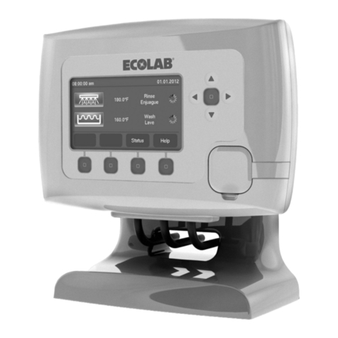
The “Controller” will indicate when pumps are running and which formula is currently selected. The
undry operator can change formulas to match the load unless MicroMode automatic sella
been programmed. Formula Load Counter: Formula load count and formula reset occurs from a pump 3
request signal. Even if pump 3 product is not required for the selected formula the signal must occur for
the formula to reset and be counted. In this case set the product 3 amount to 0.
The “Optional Flush Manifold” — not shown— provides an alternative means of chemical transfer to
the laundry machine. In flush configuration, the Advanced Laundry Control System is a complete
integrated water flush chemical dispensing system – complete with flow sensor and system alarm.

Figure 1-1
Washer
Supply
Signals
Controller
Advanced Laundry Control System Installation & Operation Manual 7

Right Side View
5
Bottom View
6
9
7
8
Advanced Laundry Control System Installation & Operation Manual 8

Advanced Laundry Control System Installation & Operation Manual 9
e Controller and the Machine Interface. Attach the 10' cable here.
1.4 Controller Description
NOTE: Paragraph numbers below refer to numbered items in Figure 1–2.
1. LED lights: The lights indicate the following:
Green light – Controller has power.
Yellow light – Controller is returning to default settings.
Red light – not currently used.
2. Infrared Communication Port: For future use.
3. Key pad: These keys provide a means for selecting/reviewing/programming:
Middle/NEXT key:
Run Mode: password and prime prompt.
Program Mode: menu advance.
Up arrow key:
Run Mode: scroll/select formula.
Program Mode: scroll options, increment displayed value, and activate (turn on) selection.
Down arrow key:
Run Mode: scroll/select formula.
Program Mode: scroll options, decrement displayed value, and deactivate (turn off)
selection.
Left arrow key:
Run Mode: view/scroll load counts.
Program Mode: step back within program menus.
Right arrow Key:
Run Mode: view/scroll load counts.
Program Mode: step forward within program menus and select options/enter.
4. LCD Display:
Run mode: Current formula number/name display, pump ru
Program mode: Data entry request/menu/settings display.
n status, load counts, and user prime.
5. Communications port: For future use.
6. “Pump Module” (DB-9 male) connector: This provides the communication link between the
Controller and the Pump Module and supplies power to the Controller. Attach the female end of the
20' cable here.
NOTE: You may also use an optional 50' cable if necessary.
7. Gnet connector: For future use.
8. System expansion port: For future use.
9. “Machine Interface” (DB-9 female) connector: This provides the communication link between
th

2.0 Specifications
2.1 Pump Module Assembly
2.2 Controller
Advanced Laundry Control System Installation & Operation Manual 10

2.3 Machine Interface
2.4 Utilities
2.4.1 Electrical Supply
•A constant 115VAC/60 Hz or 208VAC/60 Hz (check serial number label for voltage, wall outlet
power supply is required. A 7-foot power cord is provided with the 115VAC unit.
•The power must be on whenever the laundry machine is operating.
•Max ring operation is:
•0 Hz Pump Modules.
2.5
Interface to Controller connection.
The 20' (6.10 meter) cable is intended for the Pump Module to Controller connection.
An optional 50' (15.24 meter) cable is also available.
imum amperage draw for each pump running du
115VAC (+/-10%), 60 HZ ………….2.4 amps;
208VAC (+/-10%), 60 HZ ………….1.3 amps;
•A 10 amp circuit breaker is fitted to the 115VAC Pump Module.
A 6 amp circuit breaker is fitted to 208 VAC/6
Communication Cables
•Two cables are supplied with male and female DB-9 connectors.
•The internal connections – of the cables – are identical.
•The matching connectors are reversed to eliminate cross connection.
•The 10' (3.05 meter) cable is intended for the Machine
•
•
Advanced Laundry Control System Installation & Operation Manual 11

2.6 General and Environmental Specifications
3.0 Installation
3.1 Preplanning the Installation
There is no substitute for planning the installation prior to beginning the work. Several minutes in planning
may save an hour or more during the installation. The following is a list of the factors to consider:
•Location of Pump Module must be within 50' of the laundry machine.
•Locate the Pump Module at a convenient height for pump tube servicing.
•Allow room underneath the Pump Module for the optional Flush Manifold when planning flush
•
tc. Use appropriate hardware for each mounting surface, e.g. metal anchors in cement or cinder
•
uld
•er or other convenient location so that the
operator can easily see the screen and operate the buttons. Allow space on the right side and bottom of
e access.
3.2
d probes.
ces, a 50' (15.24 meter) cable may be ordered.
•Optional Flush Manifold.
•Optional controller swivel mount bracket.
installations.
The Pump Module must be mounted to a solid surface , e.g., drywall, masonry, wood, cement, cinder
block, e
block.
Verify access to the appropriate power source for the unit. A separate power supply is desirable , but
you may have to use the laundry washer power. If an external switch or circuit breaker is used, it sho
be located as close as possible to the Pump Module.
•The outlet supply tubing run should not exceed 50' (15.24 meters). The total input and output tubing
runs should be kept to less than 60’ (18.3 meters) or tubing durability will be affected.
The Controller must be mounted securely to the laundry wash
the controller for cable connections and future cabl
Materials Ordered Separately
•Product pickup and output supply tubing, an
•For long Controller to Pump Module distan
Advanced Laundry Control System Installation & Operation Manual 12

3.3 Pump Module Installation
Review the pre-planning information before installation.
1. Locate the pump module close to your product containers and close to AC power. A vertical wall
behind the washer at a 4 to 5 foot (1.22 to 1.52 meter) height is usually suitable.
2. Install the Pump Module wall mount bracket with hardware provided.
3. Hang the pump module on the wall mount bracket, pressing downwards until the Pump Module
locks in place.
4. Connect the power cable to an appropriate wall outlet or hard wire to the laundry machine. For
permanently connected equipment, the power cable should be run through conduit (flexible
preferred). Electrical connections must be made to screw terminals.
5. Cut the tie-wrap to remove the Flush Jumper Plug. Remove the Flush Jumper Plug from the flush
connector on the underside of the Pump Module. IMPORTANT: Retain the Flush Jumper Plug
for future use.
6. Connect Flush Manifold cable to flush connector on the Pump Module.
Advanced Laundry Control System Installation & Operation Manual 13

3.4 Controller Installation
3.4.1 Mounting on Vertical Surfaces (Preferred)
1. Find a suitable location for the Controller either on or close to the washer. The keypad should be
readily accessible and the display easily visible to the user.
2. Connect communication cables, Pump Module connector and Machine Signal Interface connector,
to Controller bottom. Secure cables at the Controller with tie wraps.
3. Clean the surface of the vertical mounting location with alcohol or similar to provide best adhesion
of the Dual Lock ™ strips.
4. Cut two 3” x 1” Dual Lock ™ strips. Remove the adhesive backing paper and affix both strips
vertically on the back of the controller enclosure.
5. Cut two additional 3” x 1” Dual Lock ™ strips and fasten to the strips located on the back of the
controller. Remove the adhesive backing paper and affix the Controller in the desired mounting
surface location.
6. Connect communication cables, Pump Module connector and Machine Signal Interface connector,
to Controller bottom. Secure cables at the Controller with tie wraps.
3.4.2 Mounting on Horizontal Surfaces
1. Find a suitable location for the Controller either on or close to the washer. The keypad should be
readily accessible and the display easily visible to the user.
2. Use the optional mounting bracket for installation on horizontal surfaces.
3. Attach the stainless steel mounting plate on the back of the controller with provided screws.
4. Line up the holes of stand with the holes on the side of the plate.
Advanced Laundry Control System Installation & Operation Manual 14

5. Tighten the provided thumbscrews through washers and stand to controller plate.
6. Screw stand to washer or other horizontal surface.
Advanced Laundry Control System Installation & Operation Manual 15
7. Connect communication cables, Pump Module connector and Machine Signal Interface connector,
to Controller bottom. Secure cables at the Controller with tie wraps.
3.4.3 Mounting to Machine Wall
1. Find a suitable location for the Controller on either side of the washer. The keypad should be
readily accessible and the display easily visible to the user.
2. Complete steps 2-5 in section 3.4.2 – Mounting on Horizontal Surfaces.
3. Mount the “L” bracket using the four provided mounting screws.
4. Attach the base of the optional mounting bracket to the “L” bracket using the two provided nut/bolt
assemblies.

5. Connect communication cables, Pump Module connector and Machine Signal Interface connector,
to Controller bottom. Secure cables at the Controller with tie wraps.
3.5 Machine Interface Installation
3.5.1 Mounting Machine Interface
1. Fasten machine interface to washer chassis within the wiring area. Keep machine interface and
communication cable away from high voltage wires and relays. Never parallel the cable with high
voltage lines.
2. Electrical connections between the MI and the wash machine must be made with screw
terminals.
3. Route the 10' communication cable into the washer signal wiring area through a rear knock-out.
4. Plug the 10' communication cable into the Machine Interface Module.
5. Bundle excess cable outside the washer rear. The other end of this cable will be plugged into the
“Machine Interface” connector on the Controller.
3.5.2 Signal Voltage
The Machine Interface will work with any signal voltage between 24 – 240 VAC or 22 - 24VDC. With
DC signals, polarity must be observed. Common is negative. The signals should be positive voltages.
3.5.3 Supply Trigger Wiring
1. Identify the washer supply signals. Check with technical service or with the washer manufacturer
if you are not sure of the connections.
2. Electrical connections between the MI and signal wires must be made with screw terminals. Use
the following color codes for both “Timer” and “Relay” modes – see section 4.1.1 for mode
explanations:
Advanced Laundry Control System Installation & Operation Manual 16

Wiring Notes:
•Individually wire-nut unused wires. If the washer has a single common, wire-nut all of the
commons together.
•
Advanced Laundry Control System Installation & Operation Manual 17
nnect all of the Machine
•s on the Machine Interface will light when a valid signal is received at the
respective input.
art Stop. This provides an interruption of the washer
e
1. Disconnect one wire from the machine timer motor and connect it to a screw terminal.
2. re was removed in
step 1. Connect the other end of this supplemental wire to the screw terminal.
3. hine Interface to the screw terminals in positions
4. Program the Controller for desired Chart Stop times for each pump and formula.
med to
dd product on certain “events” or fills of the machine. Regular supply signals are not needed.
her and signal wires must be made with screw terminals.
If one or more pump signals are not used they do not need to be connected.
•If you are triggering more than one pump from a single signal then co
Interface pump signal wires for those pumps to that signal.
Each of the 6 LED
3.5.4 Chart Stop Wiring
Two grey wires are present for Chart Stop connections. These wires provide a normally-closed contact
closure that opens when the Controller calls for Ch
tim r motor for the programmed Chart Stop time.
Add a supplemental wire (18g., 300V rated) from the timer motor, where the wi
Connect the two grey wires from the Mac
corresponding to the motor timer wires.
3.5.5 Event Mode Wiring
In event mode, the dispenser sequences itself to the laundry machine cycle. It may be program
a
Electrical connections between the was
Event mode wiring connections below:

3.5.6 MicroMode Signal Wiring
MicroMode allows formula selection to be performed automatically by the washer controller. The
washer controller must be microprocessor controlled and able to program supply trigger signal timed
to the second.
1. Connect any available (not used for pump activation) supply signal input to MicroMode signal
from the washing machine.
2. Electrical connections between the washer and signal wires must be made with screw terminals.
Assign the signal input you choose to MicroMode in section 4-3 (QUICKSTART) or section 4-5
(WASHER SETUP) of Program Mode.
3. Program the washer controller MicroMode supply trigger signal for ( 2 seconds * formula # + 1 ).
See examples below.
EXAMPLE: To auto–select formula 1, program a 3 second signal.
To auto–select formula 2, program a 5 second signal.
To auto–select formula 3, program a 7 second signal.
To auto–select formula 4, program a 9 second signal.
Etc... all the way to formula 16.
To auto–select formula 16, program a 33 second signal.
3.6 Communication Cables
1. Plug the 20' communication cable (from the Pump Module) into the connector labeled “Pump Module”
on the bottom of the Controller.
2. Plug the 10' communication cable (female DB-9 on cable) into the connector labeled “Machine
Interface” on the bottom of the Controller.
3.7 Supply Tubing Installation
1. Minimize supply tubing length. We recommend that you do not exceed 60' total—pump inlet and exit
lengths combined. Do not exceed a 12' maximum vertical rise.
2. Use the supplied barbed fittings to connect the supply tubing to each pump tube. Use hose clamps on
the pump tubing connections to ensure a leak-free assembly.
3. Use a standard pickup probe on the supply tubing to prevent the tube from curling out of the liquid in the
product container.
4. Minimize product drip at the washer by sloping the supply tube upwards to the washer entry point. If this
ideal situation cannot be realized then form a loop in the supply tube as close as possible to the washer
entry point. This will minimize drip at the injection point at the washer.
5. Bring supply tubes into the washer via the washer’s built-in powder supply compartment, or through a
side entry port, if available. The latter option may be preferred since it usually adds chemical to the
water, not on top of the load. If you add product through top-mounted compartments use the delay
feature of the Advanced Laundry Control System to allow the washer to fill before adding chemical.
6. Use tie wraps or hose clamps to ensure that the tubes are secured at the washer entry point.
Advanced Laundry Control System Installation & Operation Manual 18

4.0 Programming
4.1 General Information
The information provided will take you step-by-step through the programming of the Advanced Laundry
Control System Controller. Refer to figures 4-1 through 4-10 to help you access the various screens.
4.1.1 Definitions and Conventions
•Menu – a selection of action choices presented on the single-line LCD display.
•Scroll – to move through menu selections by pressing the UP arrow or DOWN arrow keys.
•Advance – to advance to other programming menus by pressing the NEXT key.
that are available for
•uring programming.
rmulas and review/edit of
•dds the programmed quantities of product when it is
med
ed.
•MicroMode – the formula selection is automatically performed via an accurately-timed supply signal
sor-controlled washing machine.
you to press and hold keys instead of repeating key
strokes.
4.1.
he controller display includes icons. The icons displayed at the top of the screen indicate which
rogramming mode is active. Following are descriptions for the programming icons:
•Enter – to press the RIGHT arrow key on the keypad.
•Programming – to set up the values, operating methods, and messages
change.
•Default – factory programmed values. These can be changed by you.
Parameters – values and limits that you set d
•Run Mode – the operator can select formulas and read total loads. The dispenser will operate
automatically as it receives supply signals.
•User Menu – the screen display when the Controller is in run mode.
•Program Mode – accessible only with password, allows construction of fo
all operating parameters.
Timer Mode – the dispenser runs pumps and a
triggered by the application of supply signals from the laundry machine.
Relay Mode – the dispenser runs each pump for as long as the applicable supply signal is present.
•
The pump stops when the signal is removed.
•Event Mode – the dispenser sequences itself to the laundry machine cycle. It may be program
to add product on certain “events” or fills of the machine. Regular supply signals are not need
input from a fully-programmable microproces
•Auto Key Repeat – a feature that allows
2 Icon Descriptions
T
p
Advanced Laundry Control System Installation & Operation Manual 19
Wrench Icon – indicates QUICKSTART and ACCT SETUP programming modes
Machine Icon – indicates WASHER SETUP programming mode
Flask Icon – indicates FORMULA PROG programming mode

File Cabinet Icon – indicates RECORDS programming mode
Advanced Laundry Control System Installation & Operation Manual 20
Hand and Button Icon – indicates PRIME programming mode
Screwdriver Icon – indicates TIME CALIB programming mode
Cross Icon – indicates DIAGNOSTIC programming mode
onal icons are displayed at the bottom of the controller screen. These icons include the
following:
4.1
u ot wire signals or program the
i and three would run at the same time.
4.1.4 Flush
T
•
•
•999 seconds).
Additi
Pump Icon – indicates that you are programming a pump or that a pump is
running. The letter designation beneath the pump (A-B-C) indicates which level
you are programming.
Clock Icon – indicates that you are programming chart stop or that chart stop is
activated.
Laundry cart icon – indicates that you are viewing load counts.
.3 Pump Lockout
P mps two and three will not run simultaneously. Do n
d spenser in such a way that pumps two
Logic
he following applies only when using the optional Flush Manifold.
A two second pre-flush begins before any pump runs.
Flush remains on while the pumps run.
•Post-flush begins after ALL pumps stop.
Post-flush time is programmable (5 to
If water flow falls below 0.65 GPM during manifold operation, all pumps will stop and, after a two
second delay, an alarm will activate.
•
Table of contents
Other Ecolab Control System manuals