Compool CP3000 Manual

Compool
Cp3000 POOL-SPA CONTROL SYSTEM
Installation & Operating Instructions
01/01/95
941-0881


SAFETY NOTICE .............................................................................. 1
INSTALLATION ................................................................................. 2
PLUMBING REQUIREMENTS .................................................................. 3
EQUIPMENT LOCATION .......................................................................... 4
HIGH VOLTAGE WIRING.......................................................................... 5
LOW VOLTAGE WIRING........................................................................... 9
SYSTEM OPTIONS................................................................................. 14
SYSTEM START-UP ............................................................................... 19
CALIBRATING TEMPERATURE SENSORS .......................................... 20
OPERATING INSTRUCTIONS........................................................ 21
INTRODUCTION...................................................................................... 21
SAFETY FEATURES............................................................................... 21
Cp3000 CONTROLLER........................................................................... 22
PROGRAMMING..................................................................................... 27
Lx3000 POWER CENTER....................................................................... 30
VALVE ACTUATORS .............................................................................. 32
SPA-SIDE REMOTE................................................................................ 32
SYSTEM OPTIONS................................................................................. 34
MAINTENANCE............................................................................... 35
PROBLEM SOLVING ...................................................................... 37
WARRANTY .................................................................................... 39
INDEX.............................................................................................. 40
Table of Contents

Compool Cp3000
1
SAFETY NOTICE
IMPORTANT SAFETY INSTRUCTIONS
WHEN INSTALLING AND USING THIS ELECTRICAL EQUIPMENT, BASIC SAFETY PRECAUTIONS
SHOULD ALWAYS BE FOLLOWED, INCLUDING THE FOLLOWING:
• READ AND FOLLOW ALL INSTRUCTIONS.
• WARNING: TO REDUCE THE RISK OF INJURY, DO NOT PERMIT CHILDREN TO USE THIS PRODUCT
UNLESS THEY ARE CLOSELY SUPERVISED AT ALL TIMES.
• WARNING: WATER IN EXCESS OF 100° FAHRENHEIT MAY BE HAZARDOUS TO YOUR HEALTH.
• A TERMINAL BAR (MARKED FOR EQUIPMENT GROUND ONLY) IS LOCATED INSIDE THE HIGH
VOLTAGE COMPARTMENT OF THE POWER CENTER. TO REDUCE THE RISK OF ELECTRIC SHOCK,
THIS TERMINAL MUST BE CONNECTED TO THE GROUNDING MEANS PROVIDED IN THE
ELECTRICAL SUPPLY PANEL WITH A CONTINUOUS COPPER WIRE EQUIVALENT IN SIZE TO THE
CIRCUIT CONDUCTORS SUPPLYING THIS EQUIPMENT.
• SAVE THESE INSTRUCTIONS.
Safety Notice

Compool Cp3000
2
INSTALLATION
PRODUCT PACKAGE
Open the shipping carton and check the contents. If any items are missing or damaged, contact your dealer
immediately.
The package should include the following items:
• CP-3000 Controller.
• LX-3000 Power Center.
• CVA-24 Valve Actuators (2 qty).
• FRE-2T 3-Port Freedom Valves (2 qty).
• 6COND Hookup Cable (150 ft.).
• Installation Hardware Kit:
½” Encloser Screws (4 qty)
1¼”Mounting Screws (3 qty)
Plastic Mounting Anchors (3 qty)
Water Temperature Sensor (w/ Hardware)
2-conductor Hook-up Cable (25 ft.)
Modular Plugs for Communication Cable (3 qty)
Test Cable with Modular Plugs (4 ft.)
SPECIAL TOOLS REQUIRED
1. 3/16” dia. Drill (for mounting Cp3000 Controller).
2. 5/16” dia. Drill (for mounting Water Temperature Sensor).
3. Crimping Tool (model TOOL-6) for mounting Connectors to Hookup Cable.
TOOL-6
Installation

Compool Cp3000
3
PLUMBING REQUIREMENTS
Recommended Hydraulic Schematic
Plumb system in accordance with recommended hydraulic schematic, local codes and the following guidelines.
Bring all lines back to the equipment pad:
1. Spa should be at or above the level of the pool. If spa is attached to pool, provide a dam between the two bodies
of water and allow spa overflow into pool. If spa is not attached to pool, an overflow, sufficient in size to carry
full pump-flow, must be installed between spa and pool.
2. Plumb a 3-port Freedom Valve on the suction-side of the filter pump, so that center port of valve is connected to
the pump inlet. Connect spa suction to one side of Intake Valve, and pool suction to the other side.
3. Plumb a 3-port Freedom Valve on the output-side of the heater, so that return water will enter valve through the
center port. Connect spa return to one port, and pool return to the other.
4. A ¾” spa makeup line (incorporating a ¾” manual gate or ball valve and, for elevated spas, a ¾” check valve)
may be provided to bypass the pool return line. This will enable some of the pool water to cycle through the spa,
thus keeping it chemically balanced with the pool. The manual valve will allow the amount of bypass to be
adjusted.
5. If an optional Spa-Side Remote is to be used, install a 6” to 12” length of 1½” Sch. 40 pvc pipe above water level
in the spa wall so that the Spa-Side Remote will not be submerged. This can be done by positioning the top of
the 1 ½” pipe ½” below the coping. The pipe should be perpendicular to the spa wall and protrude beyond the
finished surface of the spa. It will be cut back at a later date. Outside the spa, reduce the pipe size down to ½” or
¾” conduit, and run to proposed Lx3000 Power Center location at equipment pad. Use sweep elbows for turns.
The Spa-Side Remote should not be installed until spa construction is complete.
;;
;;;
CP-3000
CONTROLLER
LX-3000
SERVICE CENTER
SOLAR
SENSOR
POOL
CLEANER
PUMP
CVA-24
CVA-24
HEATER
CVA-24
SOLAR
PUMP
VACUUM
RELIEF
WATER
SENSOR
SIMMER
FILTER
PUMP FILTER
CVA-24
MAIN
DRAIN
HW-5B
SPA
ET
PUMP
BLOWER
WATERFALL
POOL
LIGHT
SPA-SIDE
REMOTE
AIR
INTAE
SPA
LIGHT
SPA POOL
Installation

Compool Cp3000
4
6. For systems which incorporate a skimmer, it is possible to balance the amount of suction between the skimmer
and main drain for maintenance purposes. This is easily accomplished by installing a manual 3-port Freedom
Valve at the suction line. Plumb one port to the skimmer and the other to the main drain.
7. If a “booster pump” type pool cleaner is being used, plumb the pump so that its suction-side is connected to the
pool return, after the heater and as close to the ground as practical.
8. A motorized 3-port Freedom Valve can be installed to create a waterfall from the return line. This enables a
waterfall effect to occur whenever the filter pump is running, and eliminates the need for a separate pump.
9. For systems which utilize solar panels, plumb the solar feed and return lines between the filter and heater, and
install a motorized 3-port Compool Solar Valve at the solar feed line. Provide a vacuum relief valve at the
highest point of the solar panel array, and a ½ lb. spring check valve at the solar return line. Use Compool Solar
Valve (model SOL-2T), to allow the panels to automatically drain whenever the filter pump is not running.
10. For solar systems with very long plumbing runs, or where panels are installed at a very high elevation (higher
than reasonable head pressure of filter pump), a solar booster pump should be installed at the solar feed line. The
motorized Solar Valve should always be used in conjunction with this pump, except where the vertical elevation
of panels above pool water level exceeds 25 feet.
11. For solar systems with glazed panels, plumb a ½” motorized Solar Drain Valve (model HW-5B) from the solar
feed line, through a check valve, to a zero psi point (such as a jet air intake or pool fill line). Do not connect it to
pump suction. This will enable the panels to automatically drain whenever the solar turns off, even if the filter
pump is still running. This prevents possible scaling of panels and damage from overheating. The Solar Drain
Valve (model HW-5B) should also be used for solar systems which do not facilitate gravity drainage of panels
(i.e.: where solar plumbing crosses the ridge of the roof).
EQUIPMENT LOCATION
With the exception of the Spa-Side Remote (which is UL Listed for installation right at the tile-line of the spa), all
equipment must be located five feet or more from the water’s edge.
1. Lx3000 Power Center at the equipment site.
2. Cp3000 Controller inside the house or other weather-protected area.
3. CVA-24 Valve Actuator(s) at valve(s) to be motorized.
4. TS-5L Water Temperature Sensor at the filter pump.
5. TS-5L Solar Temperature Sensor at solar panels (where applicable).
6. Spa-Side Remote (optional) at spa wall or decking.
Installation
Compool Cp3000
5
HIGH VOLTAGE WIRING
SUB-PANEL
At the equipment site, install an electrical sub-panel with separate breakers for each load. Circuit breakers should be
readily accessible to the pool/spa user, but installed at least 5 feet from the water’s edge.
Note: It is possible to install system without a sub-panel.
Lx3000 POWER CENTER
Lx3000
1. Select a convenient location to mount the Lx3000 Power Center. Ensure that the location is greater than 5 feet
from the water’s edge and no further than 15 feet from any motorized valves (otherwise Valve Actuator cables
will need to be extended).
2. Mount the Lx3000 on a flat surface using appropriate screws through the three external mounting points located
on the side of the enclosure.
Caution: Do not drill and mount from inside the enclosure.
3. Remove the three service panel screws in right-side of Lx3000 to expose the high voltage compartment.
4. Knock-out the appropriate holes at bottom of enclosure to facilitate conduit mounting. Screw terminals are
provided for high voltage connections.
Installation

Compool Cp3000
6
SYSTEM POWER
1. Provide a separate circuit breaker to power the system. Either 115 or 230 VAC can be used (115 VAC is
preferable). The Cp3000 system draws less than 1 amp.
Caution: Incorrect system wiring will cause permanent damage to the transformer.
2. Verify that the breaker will open all ungrounded supply conductors to comply with section 422-20 of the
National Electrical Code, ANSI/NFPA 70-1987.
3. Run appropriate wires from circuit breaker to high voltage compartment of Lx3000, and connect to top terminal
block in accordance with wiring label, which is marked “SYSTEM POWER”. The diagram above shows system
wired for 115 volts.
4. For 115 VAC, connect to Screw Terminals #2 and #3.
5. For 230 VAC, connect to Screw Terminals #1 and #3.
Installation

Compool Cp3000
7
EQUIPMENT POWER
1. Install circuit breakers to provide voltage for power relays at R1 through R4. Run appropriate wires from
breakers to high voltage compartment of Lx3000, and connect to LINE 1 and LINE 2 Screw Terminals at each
terminal block.
2. Pumps and other high voltage equipment are connected to LOAD 1 and LOAD 2 terminals. Each individual
terminal block can be wired to operate either 115 or 230 VAC.
3. Connect the high voltage equipment to LOAD 1 and LOAD 2 terminals at each terminal block. The diagram
above shows the high voltage wiring of a 230 VAC filter pump.
4. If the system is to control a pool cleaner pump, it should be connected to the R2 terminal block.
Note: For 115 VAC equipment, only half of the terminal block needs to be used (i.e.: LINE 1 and LOAD 1). The
neutral wire connects directly from the sub panel to the equipment.
ADDING RELAYS
The Cp3000 system comes standard with 4 power relays for activating the Filter Pump, Aux1, Aux2 and Aux3 circuits.
It is possible to install additional Relay Kits (model RLY-LX) to the Lx3000, in order to activate additional equipment.
Install RLY-LX in accordance with instructions provided, and plug relay control wire into Lx3000 circuit board at
appropriate Relay Socket. The Lx3000 Power Center will accommodate a maximum of 7 power relays.
LINE
LINE
LOAD
LOAD
R
LINE
LINE
LOAD
LOAD
R
LINE
LINE
LOAD
LOAD
R3
LINE
LINE
LOAD
LOAD
R
LINE
LINE
LOAD
LOAD
R
LINE
LINE
LOAD
LOAD
R
LINE
LINE
LOAD
LOAD
R
HIGH VOLTAGE RELAYS FULL LOAD 0AMP
LOCKED ROTOR 0AMP
Installation

Compool Cp3000
8
UNDERWATER LIGHTS
If the system incorporates 115 Volt Underwater Light(s), you should provide GFCI protection on the load side of the
relay (not the line side) as shown above.
Note: Low voltage lights and fiber optic lights do not require GFCI protection.
1. Run appropriate wire from circuit breaker to LINE 1 of terminal block.
2. Run wire from LOAD 1 and neutral wire from circuit breaker to GFCI.
3. Connect underwater lights to GFCI.
Note: If total load exceeds 500 watts (i.e.: two 400 watt pool lights), provide a jumper wire between LINE 1 and LINE
2 at the terminal block.
LINE
LINE
LOAD
LOAD
R
LINE
LINE
LOAD
LOAD
R
LINE
LINE
LOAD
LOAD
R3
LINE
LINE
LOAD
LOAD
R
LINE
LINE
LOAD
LOAD
R
LINE
LINE
LOAD
LOAD
R
LINE
LINE
LOAD
LOAD
R
HIGH VOLTAGE RELAYS FULL LOAD 0AMP
LOCKED ROTOR 0AMP
Installation

Compool Cp3000
9
LOW VOLTAGE WIRING
Lx3000 Circuit Board
LOW VOLTAGE CABLES
All low voltage connections are made to the circuit board which is located behind the hinged faceplate in left-side
compartment of Lx3000 Power Center.
150 feet of 6-conductor communication cable (model 6COND), and 25 feet of 2-conductor cable (model 2COND) is
provided with the system. Additional cable is available from your distributor.
Determine lengths of hookup cable required to run from the low voltage compartment of the Lx3000 Power Center to
the various pieces of equipment:
to SPA-SIDE REMOTE
INTAKE
VALVE
ACTUATOR ACTUATOR
VALVE
RETURN SOLAR
VALVE
ACTUATOR
HEATER
CONTROL
GAS VALVE
PRESSURE
THERMOSTAT
LIMIT OFF
ON
SOLAR SENSOR
WATER SENSOR
TRANSFORMER
CONNECTIONS
to CP-3000
RED
GRN
RED
GRN
RELAY CONNECTIONS
SELECT 4 CIRCUITS
RED
YEL
GRN
BLU
ORG
BLK
S
S
S 3
S
+10
GND
REM1
REMF
SPA
HLMP
REM5
REM4
REM3
REM2
HBST
REM6
WTS-
SPA
STS+
STS-
HTR
2SPD
PMP
SOL
EHTR
AUX6
AUX5
AUX4
AUX3
VLV
AUX1
AUX2
FLTR
SOL
VLV
VLV
RET
18
WTS+
FREEZ PORTHI SPD
FLTR
AUX1
AUX2
AUX3
AUX4
AUX5
AUX6
SPA
FLTR
SOLR
AUX1
SOLAR
MANHT
10 24
TO CP-3000
BLU
BLU
INT
3
ON
3
ON ON
PC-LX3000
FEATURES
COMPOOL 10890D
CAUTION: DO NOT SHORT PINS OF RELAY SOCKETS
VLV2
VLV3
VLV1
COMPOOL 11040A
MOD-VLV3
VLV1
WITH
VLV2
O
N
AUXILIARY VALVE
ACTUATORS
VLV2
WITH
VLV3
Installation

Compool Cp3000
10
1. 6-conductor 26 AWG communication cable to the Cp3000 Controller. Note: 300’ run maximum. Call Compool
for instruction for longer runs. Caution: Always lubricate cable with cable lubricant when pulling through
conduit.
2. 2-conductor 22 AWG cable to the gas heater.
3. 2-conductor 22 AWG cable to the Water Temperature Sensor.
4. 2-conductor 22 AWG cable to optional Solar Temperature Sensor.
5. CVA-24 Valve Actuators are provided with 15 feet of 3-conductor cable. Note: May be extended to a max.
length of 150’ w/ 18 gauge cable (model 3COND/VOR).
6. Optional Spa-Side Remote is provided with necessary cable attached (50’, 100’, 150’, 200’, or 250’ length).
Note: Do not install low voltage and high voltage wires in the same conduit.
Do not install temperature sensor and gas heater wires in the same conduit.
Install cables, using plastic or metallic conduit where cables run underground, through concrete, etc.
MOUNTING THE Cp3000 CONTROLLER
1. Select a convenient location inside the house or other weather-protected area to mount the Cp3000 Controller.
The overall width of the Controller (with doors open) is 11½”. The location of the 6-conductor communication
cable (on the centerline of the enclosure) should therefore be at least 5¾” from any door jamb, wall corner or
other obstacle. Install the Cp3000 Controller at eye level for best viewing of the LCD display.
2. Remove backplate from Controller. Temporarily pull cable through large hole in backplate, and position
backplate on surface of wall. Ensure that backplate is level, and that “TOP” nomenclature is oriented correctly.
Level the backplate and mark the three mounting points on the surface of the wall.
3. With the backplate removed from the wall, drill 3/16” diameter holes at the three points. Insert mounting anchors
(included) into the three holes.
4. Pull cable through large hole in backplate, and use the three 1¼” screws to mount backplate to wall. Cut off
excess cable, and use crimping tool (model TOOL-6) to connect modular plug at each end of cable. See USING
THE CRIMPING TOOL for details.
5. At the Cp3000, insert cable (with modular plug attached) into circuit board at “LINE TO LX” Socket.
Installation

Compool Cp3000
11
6. Use the four ½” screws (included) to mount Controller to the backplate.
7. At the Lx3000, insert cable (with modular plug attached) into circuit board at “to CP-3000” Socket.
USING THE CRIMPING TOOL
TOOL-6
1. Use Cutter to prepare cable end. Make sure that cable is cut squarely (not diagonally).
2. Insert the cable between the Stripper blades of the tool until it touches the stop. Squeeze the handles and pull the
tool, making sure that the cable stays perpendicular to it. If this is done correctly, the outer jacket of the cable
will be removed without damaging the insulation on the individual conductors.
3. Plug a modular connector into the holder so that the gold contacts face the Crimper.
4. Orient the prepared cable so that the blue conductor is closest to the tool handles, and insert cable into connector.
Make sure the wires go all the way to the back of the connector.
5. Squeeze the handles firmly to set the contacts and secure the cable.
Note: It is important that the orientation (blue conductor closest to tool handles) is identical at each end of the cable.
CVA-24 VALVE ACTUATORS
CVA-24
1. Remove knob, handle and four screws from cap of valve(s) to be motorized, and use the four mounting screws
provided to mount Valve Actuator(s) to valve(s).
2. Run cable(s) to low voltage compartment of Lx3000 Power Center.
3. At the Lx3000, plug cable(s) into appropriate Valve Socket on circuit board:
Installation

Compool Cp3000
12
• Plug Intake (suction) Valve to INT VLV Socket.
• Plug Return Valve to RET VLV Socket.
• Plug Optional Solar Valve (if applicable) to SOL VLV Socket.
Note: To control additional valve actuators, see AUXILIARY VALVE ACTUATORS for details.
GAS HEATER CONNECTIONS
Follow these instructions to connect a gas heater (millivolt or electronic-ignition) or propane heater:
1. Cut sufficient 2-conductor cable (25 ft. is included with Accessory Kit) to run between the heater and the
Lx3000.
2. Inside the heater, interrupt wire between thermostat and pressure switch (where fireman’s switch is typically
connected), and interconnect with 2-conductor cable using wire nuts. Do not disconnect or bypass the thermostat
or any safety switches.
3. Run cable to low voltage compartment of Lx3000. At the Lx3000, strip insulation ¼” and connect to circuit
board at the two HTR Screw Terminals.
4. Turn the heater switch to ON (or High) and set thermostat(s) to maximum.
WATER TEMPERATURE SENSOR
1. Select a convenient location to mount the Temperature Sensor (model TS-5L) between the pump and filter.
2. Drill a 5/16” diameter hole in the pipe, and insert the Sensor. Position the hose clamp over the Sensor, and gently
tighten around pipe. Caution: Overtightening of clamp can cause deformation of O-ring seal.
3. Use the remainder of the 2-conductor cable (provided with Accessory Kit) to run between Sensor location and
low voltage compartment of Lx3000 Power Center.
4. At the Sensor, pay attention to color-coding of wires (green wire connects to green; red wire connects to red), and
use crimp connectors (included) to provide waterproof connections. Before making connections, shorten sensor
Installation

Compool Cp3000
13
leads to about 6”. Do not strip wires. Push the 2 wires to be connected into the small holes at one end of the
connector, and squeeze the connector with a pair of pliers. 2 extra connectors are included.
5. At the Lx3000, connect Sensor cable to circuit board at WTS- and WTS+ Screw Terminals in accordance with
wiring diagram located inside Lx3000 door. Pay attention to color-coding of wires (green wire connects to
WTS- and red wire connects to WTS+).
Note: Infield calibration of temperature sensor(s) is required. See CALIBRATING TEMPERATURE SENSORS for
details.
Installation

Compool Cp3000
14
SYSTEM OPTIONS
SPA-SIDE REMOTE
SS4-100W
The optional Spa-Side Remote (model SS4-100W) is a double-insulated device which is UL Listed for installation
within 5 feet of the water’s edge. It is typically installed at the tile-line on the spa wall (above water level), or in the
deck within arm’s reach of the spa. If the Spa-Side Remote is to be installed into the wall of a gunite spa, provision
must be made while the spa is being plumbed (See PLUMBING REQUIREMENTS for details):
1. When the spa construction is completed, cut back the 1½” dia. pvc pipe receptacle flush with the spa wall finish
or surface of deck.
2. Screw Mounting Adapter onto Spa-Side Remote, and finger-tighten. Caution: Do not use wrench.
3. Thread Spa-Side Remote cable through conduit to low-voltage compartment of Lx3000.
4. Carefully glue Mounting Adapter into 1½” pvc receptacle using pvc cement. For aesthetic purposes, it is
suggested that the Spa-Side Remote be installed with Red button in the 12 o’clock position.
5. At the Lx3000, identify the 6-conductor cable from the Spa-Side Remote, and cutoff excess cable as necessary.
Strip insulation of each conductor ¼" and connect to appropriate Screw Terminals at bottom of circuit board in
accordance with wiring diagram:
6. Connect Black wire (Switch Common) to GND Screw Terminal.
7. Connect Orange (Status Lamp) to HLMP Screw Terminal.
8. Determine which 4 of the following circuits you wish to control from within the spa, and connect Red (Red
button), Yellow (Yellow button), Green (Green button) and Blue (Blue button) wires to the appropriate Screw
Terminals (see LX3000 CIRCUIT BOARD for details):
• SPA Rotates intake and return valves, and activates filter pump and heater.
• REMF Activates filter pump (normally not used).
• REM1 Activates auxiliary 1 equipment (such as pool cleaner).
• REM2 Activates auxiliary 2 equipment (such as pool light).
• REM3 Activates auxiliary 3 equipment (such as spa light).
• REM4 Activates auxiliary 4 equipment (such as fountain or waterfall).
• REM5 Activates auxiliary 5 equipment (such as jet pump).
• REM6 Activates auxiliary 6 equipment (such as air blower).
• HBST Enables spa heating for a five minute period.
For Spa-Side control of more than 4 pieces of equipment, a second Spa-Side Remote may be installed.
Installation

Compool Cp3000
15
A set of adhesive labels is provided for custom identification of individual Spa-Side Remote buttons. Use a pair of
fine-tip tweezers to carefully adhere the appropriate label at each button.
2-SPEED FILTER PUMP CONTROL
If the system is equipped with a 2-Speed Filter Pump, a 2-Speed Filter Pump Relay Kit (model RLY-LXD) should be
installed at the Power Center in accordance with instructions provided.
There are three ways to configure the 2-Speed Filter Pump control:
1. Automatic configuration:
The system will run the filter pump in “low speed” during normal operation, but will automatically switch the pump
to “high speed” for 5 minutes whenever the filter pump turns on.
It is additionally possible to activate the pump in “high speed” whenever the spa, heater, solar and/or Aux1 (pool
cleaner) is running. To enable the pump to run in “high speed” during these conditions, it is necessary to adjust the 4-
position HI SPD Program Switch, which is located at top center of Lx3000 circuit board. Use the corner of a small
screwdriver or other blunt instrument to slide the appropriate Switch(es) to the ON position:
Switch #1: Enables high speed when spa is running.
Switch #2: Enables high speed when heater is running.
Switch #3: Enables high speed when solar system is running.
Switch #4: Enables high speed when Aux1 (pool cleaner) is running.
Connect RLY-LXD relay control wire into 2SPD Relay Socket.
2. Manual configuration:
The system will run the filter pump in “low speed” during normal operation, but will switch the pump to “high speed”
when an Auxiliary Circuit is activated.
Select an Auxiliary Circuit (Aux1 - Aux6), and connect RLY-LXD control wire into the appropriate Relay Socket.
3. Combined configuration:
The “high speed” is controlled by an Auxiliary Circuit and the HI-SPD Program Switch. Use Dual Circuit Relay
Adapter (model CRA-LX) to connect RLY-LXD relay control wire into an Auxiliary Relay Socket and into 2SPD
Relay Socket.
AUXILIARY VALVE ACTUATORS
MOD-VLV3
It is possible to add Valve Actuators (model CVA-24) to the system to motorize two-port or three-port valves for
custom hydraulic features (such as a pool cleaner, fountain, waterfall, etc.). A total of three Valve Actuators may be
added. Valve Actuators can be activated from any Circuit.
1. Install Auxiliary Valve Module (model MOD-VLV3) at the Lx3000 low voltage compartment in accordance with
instructions provided.
VLV2
VLV3
VLV1
COMPOOL 11040A
MOD-VLV3
VLV1
WITH
VLV2
12
O
N
AUXILIARY VALVE
ACTUATORS
VLV2
WITH
VLV3
CONTROL JUMPER
SOCKETS
Installation

Compool Cp3000
16
2. Remove knob, handle and four screws from cap of valve(s) to be motorized, and use the four mounting screws
provided to mount Valve Actuator(s) to valve(s).
3. Run cable from Valve Actuator to Lx3000 low voltage compartment.
4. Plug end of Valve Actuator cable(s) into appropriate Valve Socket(s) on the MOD-VLV3 circuit board (VLV1,
VLV2, or VLV3).
5. Locate Wiring Harnesses, which are provided with the Valve Module.
6. Select which Circuit(s) you wish to use for activating Valve Actuator(s). Each Circuit will require a Wiring
Harness.
7. Plug one end of Wiring Harness into Lx3000 circuit board at the appropriate Relay Socket.
8. Plug other end of Wiring Harness into MOD-VLV3 at appropriate CONTROL JUMPERS Socket.
9. To combine the operation of VLV1 with VLV2 and/or VLV2 with VLV3, adjust the COMBINED VALVES
Program Switch (at upper left-side of MOD-VLV3) accordingly.
HIGH VOLTAGE THERMOSTAT HEATER
For systems which utilize a high voltage thermostat, such as an oil fired heater, electric heater, or heat pump, a Relay
Kit (model RLY-LX) should be added.
1. Install RLY-LX at the Lx3000 in accordance with instructions provided, and plug relay control wire onto circuit
board at EHTR Relay Socket. The relay will close whenever the Cp3000 is calling for heat.
2. Splice thermostat wiring inside heater and run wires of sufficient gauge to Line 1 and Load 1 of RLY-LX relay
terminal block.
FREEZE PROTECTION SETTINGS
It is possible to automatically circulate water through the equipment whenever the temperature drops to 35° F. This
will protect the equipment against possible freeze damage.
The Control System uses the Water Temperature Sensor to detect freezing conditions, so a separate Freeze Sensor is
not required.
It is, however, necessary to adjust the 7-position FREEZ PROT Program Switch, which is located at top center of
Lx3000 circuit board. Determine which equipment you would like to activate during freezing conditions, and use the
corner of a small screwdriver or other blunt instrument to slide the appropriate Switch(es) to the ON position:
Switch #1: Activates FLTR (filter pump) during freezing conditions.
Switch #2: Activates AUX1 during freezing conditions.
Switch #3: Activates AUX2 during freezing conditions.
Switch #4: Activates AUX3 during freezing conditions.
Switch #5: Activates AUX4 during freezing conditions.
Switch #6: Activates AUX5 during freezing conditions.
Switch #7: Activates AUX6 during freezing conditions.
When Freeze Mode starts, the Cp3000 display will indicate “FRZ” and turn on any circuit that has been selected by
the FREEZ PROT Program Switch. Equipment key icons will not show “ON” if activated by the Freeze Mode.
Switch #1 additionally cycles the pool and spa for 15 minutes each. The Freeze Mode lasts for 30 minutes. Pressing
Installation

Compool Cp3000
17
any of the equipment keys on the Cp3000 controller will deactivate the Freeze Mode.
SOLAR TEMPERATURE SENSOR
If the system incorporates solar, install an optional Temperature Sensor (model TS-5L) at the solar panel array.
1. Adjust the 2-position Program Switch, which is located at top center of Lx3000 circuit board. Use the corner of
a small screwdriver or other blunt instrument to slide Switch #1 (SOLAR) to the ON position.
2. Discard clamp (included with TS-5L). Do not drill hole and clamp sensor into solar pipe. For unglazed
panels, fasten Sensor to surface next to solar panels. Do not bolt directly to panel. For glazed panels, suspend
Sensor between collector and glazing.
3. Provide 2-conductor cable between Solar Sensor and low voltage compartment of Lx3000 Power Center.
4. At the Sensor, pay attention to color-coding of wires (green wire connects to green; red wire connects to red), and
use crimp connectors (included) to provide waterproof connections. Before making connections, shorten sensor
leads to about 6”. Do not strip wires. Push the 2 wires to be connected into the small holes at one end of the
connector, and squeeze the cylinder with a pair of pliers. 2 additional connectors are included. It is
recommended to tape connections and wiring to prevent possible damage from UV radiation. Be sure to keep
wires separated.
5. At the Lx3000, connect cable from Solar Sensor to circuit board at STS- and STS+ Screw Terminals. Pay
attention to color-coding of wires (green wire connects to STS- and red wire connects to STS+).
Note: Infield calibration of temperature sensors is required. See CALIBRATING TEMPERATURE SENSORS for
details.
SOLAR BOOSTER PUMP CONTROL
If a solar booster pump is being used, install a Relay Kit (model RLY-LX) at the Lx3000 in accordance with
instructions provided, and plug onto circuit board at SOL PMP Relay Socket.
Installation
Table of contents
Other Compool Control System manuals

Compool
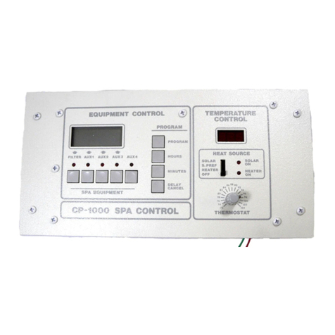
Compool Pool or Spa Control System CP-1000 User manual

Compool
Compool Commercial Pool & Spa Control System LX-80 User manual

Compool
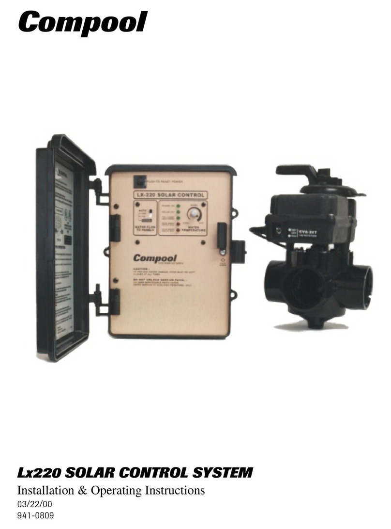
Compool Lx220 Manual

Compool
Compool Pool-Spa Control System Time Master User manual

Compool
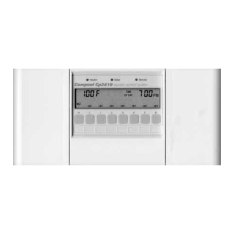
Compool Cp3810 Manual

Compool
Compool Cp3600 Manual

Compool
Compool Cp3800 Manual

Compool
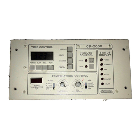
Compool Pool-Spa Control System CP-2000 User manual
Popular Control System manuals by other brands

Powrmatic
Powrmatic Vision Mini Installation & servicing manual

RTS
RTS DBP 4M Technical manual

LTI MOTION
LTI MOTION MotionOne CM Programming manual

AquaCare
AquaCare Turbo Chalk Reactor Control II instruction manual

Networker
Networker TS2500 Managers operating manual

Onstep
Onstep EQ5 GoTo Build instructions