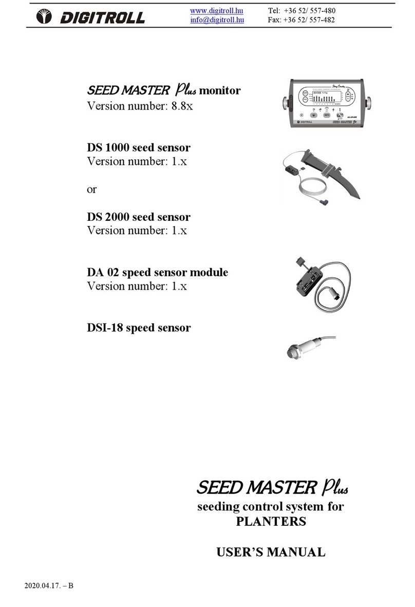
Digitroll SEED MASTER Plus 8.6 Series User manual

SEED MASTER
Plus
(version 8.6x and 8.7x)
DIGITROLL
SEED MASTER
Plus
seeding control system for
PLANTERS
USER’S MANUAL
DIGITROLL Ltd. Tel: +36 52/ 557-480 Web: www.digitroll.hu
Fax: +36 52/ 557-482 Email: info@digitroll.hu
1
1
2
2
3
3
4
4
5
5
6
6
7
7
8
8
910 11 12 13 14 15 16
SENSORS
ALL-IN-ONE
IN TE L L I G EN T S EN S O R T E C H N OL O GY
STOP
DIS PLAY
TEST
INFO
A
B
C
D
100%
150%
50%
0%
OUT
A B C D
+1
L
R
max.
STOP
DIGITROLL
86000 */ha
ÿ
ÿ
ÿ
ÿ
ÿ
ÿ
ÿ
ÿ
ÿ
ÿ
ÿ
Ã
Å

SYSTEM DRAFT
2
SYSTEM DRAFT
Seeding control system for planters 1-16 rows with area counter
AKKU
PIROS KÉK
OPTO MODUL
OPTO MODUL
SPEED MODUL
OPTO MODUL
OPTO MODUL
OPTO MODUL
3.1. 2. 4. MAX.
16.
RADAR-II
DSI-18J
RAD/HIR/4
5m
2m
6m
DA 02
SPEED MODUL
12VDC
1
1
2
2
3
3
4
4
5
5
6
6
7
7
8
8
910 11 12 13 14 15 16
SENSORS
ALL-IN-ONE
IN TELL IGENT SEN SO R TE CH N OL OGY
STOP
DISP LAY
TEST
INFO
A
B
C
D
100%
150%
50%
0%
OUT
A B C D
+1
L
R
max.
STOP
DIGITROLL
86000 */ha
ÿ
ÿ
ÿ
ÿ
ÿ
ÿ
ÿ
ÿ
ÿ
ÿ
ÿ
Ã
Å
DS 1000 -custom designed for seeder type, placed in seed tube
DS 2000 - custom designed for seeder type, placed in coulter
RED
BLUE

3
CONTENT
SYSTEM DRAFT ........................................................................................................... 2
GENERAL DESCRIPTION ........................................................................................... 4
MOUNTING ................................................................................................................... 6
MONITOR FRONT ........................................................................................................ 7
SWITCH ON .................................................................................................................. 7
SYSTEM TEST .............................................................................................................. 8
MENU ............................................................................................................................. 9
SETTING BASIC DATA ............................................................................................. 10
MONITOR SETTINGS ................................................................................................ 13
CONTROL OF SEEDER SETTINGS .......................................................................... 14
SEEDING CONTROL .................................................................................................. 16
STORED SEEDING DATA ......................................................................................... 19
DISTANCE MEASUREMENT ................................................................................... 20
TROUBLESHOOTING ................................................................................................ 21
MAINTENANCE, STORAGE ..................................................................................... 24
WARRANTY PROVIDED .......................................................................................... 24

GENERAL DESCRIPTION
4
GENERAL DESCRIPTION
SEED MASTER
Plus
MONITOR
· illuminated LCD display
· massive aluminium housing
· audible and visual alarms
· adjustable horn volume
· 8 selectable languages
· nonvolatile memory for safe storage of measured and adjusted data
SYSTEM CONSTRUCTION
· infrared sensation
· connected in linear string system up to 16 rows
· modules are exchangeable, their sequence is determined automatically
when connected
· harness-free network - easy cabling and mounting
SYSTEM TEST
Sensordiagnostics.
· automatic recognition and readiness test of photosensors
· dusty or blockaged sensor display
CONTROL OF SEEDER SETTINGS
· Statistics of 100 expected/seeded grains
· Average seeded grains (Population ratio control)
SEEDING CONTROL
· Simultaneously detected seeding continuity on all rows
· Selectable seed dize and shape
· Adjustable missing seed time interval for error signal
· Skip continuously unused rows
· display hold function helps analyze actual seeding situation
· Individually adjustable seed spacing for each row
· Seed counting
· Easy to use seeding blockage control mode. Unnecessary any settings.
· Population ratio control with bar diagram
· row display setting
HECTARE COUNTING
· Measure and store total and partial seeded area to 999,99 ha
· Distance measurement to 65 000 m
· Start/stop measuring by signal of photosensors
· If photosensors are not applied, the counting is continuously.

GENERAL DESCRIPTION
5
STORED SEEDING DATA
· Number of seeded grains
· Hectare
· Average population/hectare
SYMBOLS APPLIED
*
Seed
B
Recognized photosensor
N
Dusty photosensor
x
Fully endusted, clogged or defected photosensor
.
Skipped row
Oo
Small, large grains (for DS 2000 photosensors)
J
Bar diagram for population ratio control
M
Total area
L
Partial area
RS
Horn volume
TU
Tractor
The seeding control system and its technical characteristics described in this manual
are under patent process.
Any means of recording or public use of principles, images, system drafts are subject
to prior written contribution of DIGITROLL Kft.

MOUNTING
6
4-6 mm
Útjeladó
Csavarfej
MOUNTING
MONITOR
Place the monitor on a clearly visible place in the tractor cabine and fix it with
the U-bracket and bolts, up or bottom position to avoid direct sunlight on
LCD. The display is illuminated which enables nighttime use with superb
visibility
• The monitor is connected optimally after a fuse (max. 3A) on 12 VDC,
taking care of the right polarity.
• Connect the extension cable of moduls to the monitor.
• Do not connect in line with other disturbing signal emitter
devices.
• Welding works are allowed only when both power cables of
the monitor are disconnected from the tractor’s electronic
system.
SPEED SENSOR FOR HECTARE COUNT
Mount speed sensor in front of a non-slipping wheel.
The best is a freewheel which sized to give at lest 1
signal in a distance traveled between 0,2 – 0,99 m.
The speed sensor gives you information about the
distance traveled.
Speed sensors are inductive sensors, in proximity of an iron part e.g. bolt
heads give a signal. If distance between sensing bolt heads would be more
than 1 meter, additional bolt signallers has to be mounted. This way, during
calibration the distance traveled in 100 bolt signals remains under 100 meters.
Checking operation:
• red LED at the end of speed sensor
• a symbol of speed sensor is blinking on monitor front
Important: when planning the placement of speed sensor regard the risk
Very important to adjust speed
sensor within the sensing distance,
generally between 4-6 mm from bolt
head.

MONITOR FRONT
7
Seed Counting Pro
v8.71
DIGITROLL Ltd.
of straw residues or pebbles, they may hurt the sensor.
MONITOR FRONT
Every push of a button is accompanied by a short beep in case the button is
operative in that function.
SWITCH ON
Then appear the system test, which is followed by the display of test
results.
1
1
2
2
3
3
4
4
5
5
6
6
7
7
8
8
910 11 12 13 14 15 16
SENSORS
ALL-I N-ONE
IN TEL LIG EN T S EN SO R TEC H N OLO GY
STOP
DISP LAY
TEST
INFO
A
B
C
D
100%
150%
50%
0%
OUT
A B C D
+1
L
R
max.
STOP
DIGITROLL
86000 */ha
ÿ
ÿ
ÿ
ÿ
ÿ
ÿ
ÿ
ÿ
ÿ
ÿ
ÿ
Ã
Å
wheel-LED
display
hold
system
test
population ratio
control
information,
data entry
seed stoppage
control
horn
spin up &
down
settings
module current
supply control
LED (blinks or
get dark when
shortcut
occurs)
>
RS...
>
<Normal >
Jf?e
~
20.0 cm
TU<J* * *
J>
Following switch on the console presents
running software version,
selected horn volume,
seed spacing values,
and offers instant setting options.

SYSTEM TEST
8
SYSTEM TEST
The system test is executed:
• every switch on,
• by pressed button on screen of any seed control mode
• automatically by change settings of photosensors.
During test process the monitor detects:
• which modules are connected to the system (photosensors, speed
module),
• what is the readiness for operation of connected photosensors
(operability, dust level check),
• Sends data to adjustable modules (DS2000).
Having the test finished, the ‘found’ modules are presented on display:
After photosensor test the seed blockage control screen appears. After
simply switch on, the monitor is ready to control seeding blockage! This
function is available without entering any date. See detailed description at
the CONTROL OF SEEDING BLOCKAGE.
TEST
SENSOR
TEST
.........
* No photosensors!
1 2 3 4 5 6
1.50 sec
x N
B B B B B B
B Operating sensor
N dusty sensor
x seeding blockage
TEST function may be used when there is
no seeding in progress!
unsuccessful test result

MENU
9
MENU
INFO
POPULATION RATIO
DISPLAY, ACTUAL
SEED/HA
PARTIAL SEEDS AND PARTIAL
AREA
AVERAGE SEED/HA
TOTAL SEEDS AND TOTAL
AREA
AVERAGE SEED/HA
ENTRY OF WORKING WIDTH
SETTING OPTIMAL SEED
SPACING
Normal or Hybrid
SETTING MIN. AND MAX.
LIMITS FOR POPULATION
CONTROL
SELECTION OF SEED
SEED SIZE SHAPE
ENTRY OF DISTANCE
TRAVELED IN 100 SPEED
SIGNALS
100 SPEED SIGNAL COUNT
SETTING DISPLAY
LANGUAGE SELECTION
ADJUSTMENT OF HORN
VOLUME
CONTROL OF SEEDING
BLOCKAGE ADJUSTABLE
SENSITIVITY
STATISTICS OF 100
SEEDED GRAINS
2 sec.
TE S T
STATISTICS OF 100
SEEDED GRAINS
2 sec.
TE S T
DISTANCE MEASUREMENT
SETTING ROW SKIP

SETTING BASIC DATA
10
SETTING BASIC DATA
SETTING OPTIMAL SEED SPACING
Two options are available:
Normal
One spacing value can be entered.
Hybrid
Select hybrid spacing when seed spacings are not desired to be the same in all
rows. The monitor program gives here the option to set individual spacing
value for each row.
Spacing value can be set directly after switch on, too.
SETTING MIN. AND MAX. LIMITS FOR POPULATION
CONTROL
c Maximum limit: alarms when population get over set value.
d Minimum limit: alarms when population get under set value.
Disable audible alarm: c151%
d0%
Shift to Hybrid
STOP
DISPLAY
<Normal >
Jf?e~20.0 cm
TU<J* * *
J>
Spinner up & down
Adjustment between 3,0 - 45,0 cm
Shift to Normal
STOP
DISPLAY
<Hybrid >
f?e~20.0 cm
1. * *
<BGBBBBBBBBCCCCCC>
Spinner up & down
aRS >
e120%c90000 */ha
100%= 75000 */ha
< 80%d60000 */ha>
Shift between
values
TE S T
Spinner up & down

SETTING BASIC DATA
11
SELECTION OF SEED SIZE AND SHAPE
In order to reach more precise seed detection when using DS 2000
optomodules, main seed characteristics like size and shape must be entered. It
brings more efficiency in recognition of double or triple seed drops.
Changes made in this menu are followed by a system test.
EDITING ROW SKIP
In case rows equipped with photosensors are temporarily not in use,
continuous alarm can be embarrasing. To eliminate this problem, switch off
control in that row.
After system test all connected sensors are displayed (regardless of being
switched on or off).
However, skipped rows are not involved in seeding control and are indicated
by a (.) character.
SEEDING ROW DISPLAY SETTING
Enhanced visibility can be reached by doubling the distances of the displayed
seed sensors on screen (up to 8 rows).
If seeder has more than 8 rows, a short warning alarms you at expansion
attempt. This case the program automatically reset short row display.
Selection of seed shape
(round or long)
DS2000 *: 6-9mm>
DS2000/HR
DS2000/HR *: o >
Selection of seed size
(3-5 / 6-9 mm)
<
BBBHBB..BBBB 4>
STOP
DISPLAY
Row skip on/off
Step row
BBBBBBBBe
12345678 >
B B B B B B B Bf
1 2 3 4 5 6 7 8 >

SETTING BASIC DATA
12
ENTRY OF WORKING WIDTH
Seeding machine working width is adjustable between 0.75-30 metres
This constant is needed for area count.
Working width can be calculated: row number multiplied by row spacing.
100 SPEED SIGNAL COUNT
This is a side function to get information about distance traveled in 100 speed
signals.
Pull/tow seeding machine on field until 100 speed signals are counted, then
measure distance traveled between 0. and 100. signals with a measure
tape on the ground. Enter distance value in the monitor in centimeters. A
warning beep sounds from 90. speed sensor signal to slow down.
Speed sensor is an inductive sensor which detects bolt heads of a driven
wheel.
In case of individual installation the number of signalling bolt heads must be
enough to provide at least one signal at every 30-60 cms distance traveled
and it may not exceed 100 cms.
Readiness for operation is indicated by a flashing SPEED SENSOR LED
on the monitor. Accurate measurement can be reached if speed sensor exactly
aligns bolt head when starting calibration. Besides signal counter on screen
watch this red LED as well, which shows you how sharply the sensor aligns
the bolt head, both at start and end points.
Measurement of distance traveled between 0-100. speed signals:
JX>
TU<J|? 4.50 m
JY
>
Spinner up & down
TU
100|Ü------------|0
START>
TU
100|Ü------------|0
START>
TU
100|Ü------------|0
100
START>
0.
90.
100.
Nomber of speed
signals =
Distance travelled = ??? cm
Csavarok
wheel sensor
START
SLOW DOWN
STOP

MONITOR SETTINGS
13
• In case of individual installation find a possibly non-driven wheel for
speed sensor, where slip rarely occurs.
• In order to reach maximum accuracy in calibration take soil conditions,
tyre pressure, hopper weight (ideally half filled),...etc. into consideration
to create similar conditions to real circumstances.
• Adjust distance between DSI-18 speed sensor (M18 thred) and bolt head
to 4-5 millimeters and consider accidental lateral wheel movement, as
well.
• Proper speed sensor adjustment has vital importance, it should signal at
the proximity of each bolt head. LED indicates it by blinking both on the
sensor and the monitor!
SETTING OF DISTANCE TRAVELED IN 100 SPEED SENSOR
SIGNAL
The distance traveled can be determined either:
• by MEASUREMENT: with a measure tape ( it is always more
accurate method since average slip is also included)
• by CALCULATION: × wheel perimeter (cm)
MONITOR SETTINGS
ADJUSTMENT OF HORN VOLUME
LANGUAGE SELECTION
TU ? >
|Ü------------Û|
60.0 m
>
spinner up &
down
>
RS))..
>
Magyar
Change language>
100
number of
bolt heads
The program enables the selection of
one language out of the 8 followings:
Hungarian, Slovakian, Ukrainian,
English, German, French, Italian,
Spanish.

CONTROL OF SEEDER SETTINGS
14
CONTROL OF SEEDER SETTINGS
STATISTICS OF 100 EXPECTED/SEEDED GRAINS
To reach this function push button for at least 2 seconds.
The appliance calculates the seeding time of 100 seeds on the basis of the
given distance, the optimal seed spacing and current speed. During this time it
counts tha actual number of the seeds in each row (in max 6 rows), and it
monitors the distance between the seeds while giving feedback. The result is
displayed after the measuring time is up.
M*- total measured seeds
** - number of double seed drops
*O- number of missing seeds
Holding the constant speed precisely is a condition of exact masuring
The data of the next row is visible after each measuring cycle.
While measuring the appliance also counts the seeds and measures the
hectares.
v8.6x program
Rows can be stepping manually only between two measure.
v8.7x program
The measuring is paused by pressing button. Row stepping manually is
possible only at this time.
TE S T
<STOP 100 opt.* TU
M*:000 f-
**:000
*O:000 2.>
step row
STOP
DISPLAY
2 sec.
TE S T
STOP
DISPLAY
pause
< 100 opt.* TU
M*:000 fM
**:000
*O:000 2.
< 1. 100 opt.* TU
M*:000 f-
**:000
*O:000 Start>
STOP
DISPLAY
step row
The measuring is started by
keypress.
The measuring is
continuous.

CONTROL OF SEEDER SETTINGS
15
If time interval between seed drops is smaller than expected:
• Use of unsuitable seed disk results homogenous, but too dense seed
drops. This case the program does not interpret it as double drop, but
the number of measured seeds will be higher than 100.
• Too high vacuum causes the pick up of two or more seeds in one seed
disk hole. Incorrect singulator adjustment leads to similar problems
that result in multiple seed drops. This case time interval between
drops is very close, the program indicates double drop and seed count
is also more than 100.
If interval (=distance) between seeds is more than double of expected, the
program interpret is as missing seed. Actually either seeds are missing or
seed spacing is inhomogeneous.
To determine real problem source, total seed count can help:
• Total seeds are around 100: inhomogeneous seed spacing (improper
seed separation, hindered seed drop…etc.)
• Total seeds are less than 100: seeds cannot be picked up from seed
feeder (inadequate air pressure, low hopper level, wrong selection of
seed disk hole diameter…etc.
In case of mixed symptoms (both multiple seed drops and missing seeds) total
seed count may indicate the resultant of the two factors.
STATISTICS OF AVERAGE SEEDED GRAINS
In order to observe seeding homogenitiy in a longer period and analize related
seeder settings, an effective tool is the bar graph display method. The monitor
collects and displays data on the average of 40 m.
Numeric values of rows are accessible by pushing button repeatedly.
Analizing these data even slowly developing processes, tendencies can be
observed (loosing pressure, lowering seed level in hopper, increasing dust
layer on photosensors…etc.).
(See detailed description at CONTROL OF POPULATION RATIO.)
STOP
DISPLAY

SEEDING CONTROL
16
SEEDING CONTROL
CONTROL OF SEEDING BLOCKAGE
The monitor simultaneously detects seeding continuity in all rows. Where seed
drop is missing for longer time than preset limit value, seed symbol of that row
(*) will disappear from display and alarm sounds in according length.
You can set missing seed time interval between 0.25 – 2.00 seconds in 6 steps.
During the turnings at landmarks alarm is disabled automatically.
This function mode is recommended when
• Small (less than 5 mm diameter), hardly detectable seeds are sown
• Necessary basic data are not entered in the monitor
• Speed sensor is damaged
• Sensor performance wanted to check at stopped seeder position
Push button to freeze display (alarm sounds haltingly) and analize actual
seeding situation even when seeding machine is stopped.
Example of display at a 6-row planter:
Missing time
interval
adjustment
STOP
DISPLAY
2.00 sec
****************
BBBBBBBBBBBBBBBB
STOP
DISPLAY
1 2 3 4 5 6
1.50 sec
* * * *
B B B B B B
Rows 1,3,5 and 6 are contineously
seeding within preset limit value.
In rows 2 and 4 seeds are missing within
the 1.5 seconds preset limit value.

SEEDING CONTROL
17
084500 */ha
JJJJJJJJJJJJJJJJ
JJJJJJJJJJJJJJJJ
CONTROL OF POPULATION RATIO
You can read the ratio of the desired and the actually measured population in
each row, displayed with bar graphs.
Use this function for seeds that can be detected precisely by the photoelectric
cells (seeds larger than 5 mm, such as maize, sunflower, sugar beet, etc)
Necessary basic data
• Optimal seed spacing
• Distance traveled in 100 speed signals
• Working width
Any measurement results true values only if basic data are entered correctly!
Start
:
Display
Do not mix up the actual seed/ha value displayed here with the total area seed/ha,
which is shown by pushing the INFO button! See also STORED SEEDING DATA.
Alarm
The monitor alarms you when difference goes beyond min. or max. limit
values. (See detailed description at SETTING MIN. AND MAX. LIMITS FOR
POPULATION CONTROL.)
If the row error is sustained, the audible error signal is continuously. If a row
is excluded from seeding, must skip it from controlling too. (See SETTING
ROW SKIP)
J
JDJ
When you start this function this screen
appears until sufficient data for displaying are
collected (cca.10 meters).
The accuracy of seeding can be surveyed
simply and visibly from 0-150 % with a
resolution of 6.25 %. Bar graphs and actual
seed/ha value are calculated over seeded
grains in cca. 40 meters distance traveled.

SEEDING CONTROL
18
Display hold
To ease analysis, display can be freezed (fixed) any time, even when seeder is
stopped.. In this case the monitor scans row diagrams and their values are
shown numerically.
Turning
Stoppage
An example of displaying on a 12-row planter:
1 2 3 4 5 6 7 8 9 10 11 12 13 14 15 16
STOP
DISPLAY
084500 */ha 3.
Á120%
JJJJJJEJJJJJJJJJ˙
JJJJJJJJJJJJJJJJSTOP
1 2 3 4 5 6 7 8 9 10 11 12
086000 */ha
D
JJ JJJJJJ JJ
JJJJJJJJJJBJJ
Push button again to
return seeding control mode.
J
JDJ
At landmarks, when every row stop
seeding, the console stores seeding data
and, according to preset limit time, displays
missing seeds and sounds alarm shortly.
When seeding is restarted the screen
displays saved data
084500 */ha STOP
˙
BBBBBBBBBBBBBBBB
If seeder stops or speed sensor is damaged,
the monitor delete screen display and
shows the symbol of population ratio
control and the fact of seeding stoppage.
• Rows 1,2,4,5,7,8,9,11 and 12 perform
seeding at 100%
• Row 3 seeds half quantity (cca. 50%)
• Row 6 overseeds with more than 19 %
• Row 10 stopped seeding
STOP
DISPLAY

STORED SEEDING DATA
19
STORED SEEDING DATA
SEEDED GRAINS AND AREA COUNTS
The SEED MASTER Plus monitor continuously measures here (and in both
seeding control mode) the seeded area and the number of total seeded grains.
The area count controlled (start/stop) by signals of photosensors. If
photosensors are not applied, the counting is continuously.
The seed/ha value, as a dividend of total seeded grains and total area, is
displayed after 0.5 hectares seeded area, until this point a “???” symbol
displayed.
You have the option to measure
¢ - Total (accumulated) and
¡ - Partial area.
Partial area counts and seeded grains are added to the totals and can be
cancelled together or separated.
In both cases area can be measured up to 999,99 hectares and relevant seeded
grain number up to 1 billion seeds.
Cancel data
• Push reset button continuously ( for cca.2 seconds), until the result of
cancellation appears on display.
• Seeded grains and area values are deleted together.
• Deleting partial area does not reset total area value.
• Deleting total area cancels partial area, too.
INFO
M: 221000 */ha
014884200 *
<0 067.39 ha
3Avarage seed/ha
3Seeded grains (rounded up to 100)
3Hectare
L: 221100 */ha
004884000 *
<0 013.25 ha
TE S T

DISTANCE MEASUREMENT
20
DISTANCE MEASUREMENT
The date of distance traveled in 100 speed signal is used here.
Measurement begins when START button pushed, appears new display on
screen, and it ends by the next push of the button.
Deletion of measured distance: push button lastingly for approx.2
seconds.
<0 TU
|Ü------------Û|
0 m
START>
STOP
DISPLAY
Deletion
up to 65.500 meters
<0 TU
|Ü------------Û|
600 m
STOP>
STOP
DISPLAY
This manual suits for next models
1
Table of contents
Other Digitroll Control System manuals
Popular Control System manuals by other brands
Distech Controls
Distech Controls DA-020S Series Hardware installation guide
GE
GE Mark VIe System guide
Toshiba
Toshiba TOSVERT VF-PS1 instruction manual

DEEP SEA ELECTRONICS
DEEP SEA ELECTRONICS DSE8610 MKII Operator's manual
Arjo
Arjo Alpha Active 4 Instructions for use
Mitsubishi Electric
Mitsubishi Electric AT-50B Instruction book
