Factair F4500 User manual

F4500 & F4500ED SAFE-AIR TESTER
OPERATING MANUAL
FAC QAM 181 Issue F 03/21

1

2
Contents
Page No
Introduction
3
Calibration & Warranty
3
Equipment List
4
1
-
Pre Use
5
2
-
Start-Up
6
3
-
Selecting the test standard and configuring the
instrument.
7
4
-
Initiating a Breathing-Air Test
8
4.1
-
Breathing-Air Tests –Airline up to 10 bar
10
4.2
Breathing-Air Tests - HP systems 200 & 300 bar
16
5
6
-
-
Continuous Oxygen Reading
Reviewing Test Results
20
21
7
-
Exporting Test Results and PC Software
22
Appendix 1 - Helpful Tips
24
Appendix 2 - Draeger Tube Tip Cutter
25
Appendix 3 - Reading the Draeger Oil Impactor and Chemical
Reagent Tubes
26
Appendix 4 –Breathing Air Standard
31
Appendix 5 –Breathing Air Quality Testing –Why?
32
Frequency of BA Tests / Recording results
33
A.4.5 Compressed Air for Breathing Apparatus
from EN529
35
COSHH L5 Sixth Edition
36
Respiratory Protective Equipment at Work
38

3
Introduction
Safe-Air Testers are designed to provide a quick and easy method for carrying out accurate periodic
testing of breathing-air supplies. The European Standard for breathing-air quality is EN12021, which
should be referred to in conjunction with any overriding national standards.
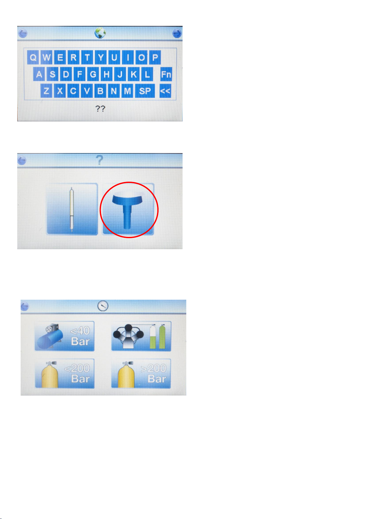
The F4500 is designed primarily for use on airline systems up to 10 bar but can also test high pressure
charging systems when used in conjunction with the F3002 High Pressure Regulator.
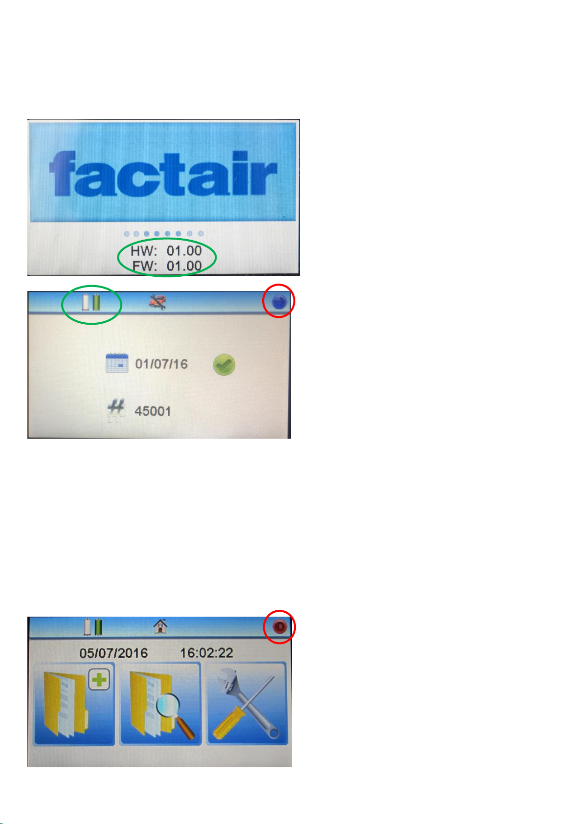
The instrument has a colour touch screen display and is supplied in a hard weatherproof case with
storage provision for a wide range of accessories and equipment. It is primarily designed to be used
from within the case; however the tester can also be removed and operated separately where space
is at a premium.
The test is carried out using the Draeger Impactor for oil and chemical reagent tubes for carbon
monoxide, carbon dioxide and water*. These are supplied in packs of 10 per type and the chemical
reagent tubes show the degree of contaminant present as a colour change to the crystals that they
contain. The extent of this is read against the scale on the tube. For the Impactor the degree of oil
contamination is displayed on a screen.
Calibration and Warranty
Safe-Air Testers leave our factory with a 12-month warranty and calibration certificate. Our standard
turnaround on annual calibration is 10 working days providing there is no major damage that requires
an extensive rebuild. (Allow an extra 5 working days for calibration of ED versions.)
Note:- Please download all stored data before returning the Tester to Factair.
Temperature Parameters
Storage: -5/+40°C Operating Range: 5/40°C
In regards to operating temperature please note stated Draeger tube accuracy is based on a test
temperature range between 15 to 25°C
This tester is calibrated for the following approved reagent tubes/Impactor.
H2O (Water-reagent tube)* Draeger ref. 6728531
CO (Carbon monoxide-reagent tube) Draeger ref. 6728511
CO2(Carbon dioxide-reagent tube) Draeger ref. 6728521
Oil (Impactor) ** Draeger ref. 8103560
*Note:- A water reagent tube is not required with the F4500ED which will automatically record the
moisture and dewpoint readings
**Note:- The tester can also be used with the old type Draeger reagent tube for oil, ref 6728371.
(Refer to Appendix 2 at the rear of the manual for instructions.)
IMPORTANT –IT IS RECOMMENDED THAT YOUR SAFE-AIR TESTER IS RETURNED FOR
RECALIBRATION AND SERVICING WITHIN 12 MONTHS FROM THE ISSUE DATE OF ITS CALIBRATION
CERTIFICATE

4
Equipment List:
F4500 Safe-Air Tester
Hard Case
Mains Power Supply
USB Memory Cable
6 x AA Alkaline Batteries
Travel Container for used detector tubes
Tube Tip Cutter
F2193 Connection adaptor terminating in a CEJN plug
Stylus Pen
Optional Extras
F3005 20 Bar Regulator
F3002 200/300 Bar 5/8” DIN thread High-Pressure Regulator
Battery Tray
Mains Input
USB Connection
Power On
Air Inlet
Flow Control
Valve
Colour Touch
Screen Display
Sintered Outlet
Oil
Water
Carbon
Dioxide
Carbon
Monoxide

5
1. Pre-Use
F4500 Safe-Air Testers are fitted with internal lithium rechargeable batteries and in addition also have
a battery tray which accommodates 6 off size AA alkaline type batteries packed separately and stored
underneath the tester within the case. In the event that the rechargeable batteries are not
sufficiently recharged then you can continue to use the instrument with either the Alkaline AA
batteries or mains power supply.
To install the alkaline AA batteries lift the tester out of its case, open the battery drawer at the rear of
the unit and place the batteries inside.
Note: - It is important to strictly observe polarity when fitting batteries and ensure that they are
correctly located.
During use the battery condition is displayed on the screen as shown below -
If the tester is to be used adjacent to a power socket, the mains adaptor may be used. Please note
the unit should be switched off prior to connection or disconnection of the mains supply.
When connected to a mains power supply the internal lithium batteries will be recharged.

6
2. Start Up
To carry out a test first switch on the machine by pressing and holding the green “on” button, located
on the right-hand side of the unit, for approximately 3 seconds.
A splash screen will be displayed which shows the
instruments hardware and firmware versions.
Periodically the firmware is upgraded as part of
the recalibration process as improvements are
identified.
A Stylus pen is provided for use with the touch
screen. The display will show the, date last
calibrated, serial number and a tick or cross
symbol will indicate whether it is within the
recommended calibration period.
The F4500 series has 2 battery level displays, the
left hand one is for the alkaline AA batteries, if
fitted. The right hand one is the rechargeable
internal lithium battery. Unless the instrument is
connected to a mains power supply the
instrument will use the highest of the 2 battery
power sources.
Please note if alkaline AAs are inserted whilst the
unit is on, their battery level will not be displayed
until the unit is turned off and back on again.
Press the arrow key to progress to the main
menu.
The main menu has 3 options available from left
to right these are: Begin Test, Review Previous
Tests and Set-Up Menu.
Each of these sub-menus are described in further
detail below
The instrument can also be turned off from this
menu by pressing the red power symbol in the
top right hand corner.

7
Note –If the begin test icon is in greyed out this
will be because no test results are currently stored
on the tester.
Note –If the begin test icon is in greyed out this
will be because the instrument’s memory is full
(20 tests maximum) and you need to remove at
least 1 test before you can proceed. See Section 4
–Reviewing Test Results for further details.
3. Selecting the test standard and configuring the instrument
From the main menu press the Configure icon.
In the configuration sub menu there are 3 icons
available, from left to right these are:
Set Date
Set Time (the instrument uses a 24 hour clock)
Set units of measure and test standard
To set the date, press the calendar button on the
display as seen above.
In this menu you can then choose date format;
DD/MM/YYYY or MM/DD/YYYY

8
The times are set prior to the unit being supplied
but they can be adjusted as necessary.
To select the test standard or the units of
measure press the right hand icon.
In this menu you can then choose the following;
CO2sample rate, pressure and temperature units
of measure and the breathing-air test standard.
Once you have made your selection press the
arrow in the top right corner to exit. To then exit
from the configuration sub menu to the main
menu press the arrow at the top left of the
screen.
4. Initiating a Breathing-Air Test
Having selected the breathing-air standard
EN12021 in the configuration screen, to carry out
a test press the “Begin Test” icon on the main
menu
The unit will automatically calibrate the oxygen
cell against the surrounding atmosphere; the unit
therefore needs to be in a well ventilated area.
Note:- If the temperature is greater than 40°C
inside the instrument the calibration will operate
for an extended period to stabilise the Oxygen
cell.

9
You now have the option of entering a
description for the test location, if you wish to
use numbers press the “Function” button. Push
the right arrow button when you are ready to
proceed.
Choose between using a Draeger chemical
reagent tube or Draeger Oil Impactor in the test
port.
For further details on alternative chemical
reagent tubes see appendices 2 and 3.
For breathing-air tests the standard option is to
select a Draeger oil Impactor.
The unit has 4 breathing-air test programmes
available: Airline Systems up to 40 bar (top left);
High Pressure Charging Compressors (top right)
High Pressure Systems up to and including 200bar
and High Pressure Cylinders above 200bar. All of
the high-pressure tests require the use of the
F3002 regulator which has a DIN connector that
can accept input pressures up to 300bar.

10
4.1 Completing an Airline (up to 10 bar) Test
Select (Airline < 40 bar) –note the maximum
pressure the instrument is rated to is 10 bar.
The F4500 can be configured with the Draeger
6728531 water tube for 2 different scales. Select
the appropriate water range: 50 to 2000 mg/m3is
for standard airline systems with a fridge dryer or
no dryer and 5 to 200 mg/m3is for systems
incorporating desiccant dryers. Having selected
the appropriate range press the arrow key.
(This screen will not appear on the F4500ED)
With the flow control valve in the closed position
connect to the air supply to be tested. Ideally this
should be done by using the hose which normally
supplies the breathing apparatus. Fit the
appropriate adaptor to the Tester first and then
connect the supply hose to the adaptor.
A test can be carried out at any pressure between
2 and 10 bar.
Note:- If the unit is over-pressurised it will
automatically shut down and display an
overpressure warning; it will then need to be
returned to the manufacturer for checking and
resetting.
Input pressure will be displayed on the measured
pressure bar graph and the adjacent display.
System pressure will automatically default to this
reading.
Note:- The pressure dewpoint at the end of the test will be calculated on the recorded system
pressure.
For the majority of applications the system pressure can be left at this default setting, however if the
breathing-air system is distributed as breathing air at a different pressure to that being displayed this
should be entered at this stage.

11
To enter press the right hand side (Set) icon use the keypad to enter the required value, press the
right arrow to return. The (Reset) button will automatically reset the system pressure back to the
measured pressure.
Press the arrow key to proceed.
We can now confirm the flow and pressure is
adequate for your respiratory protective device.
Adjust the system’s flow control valve so that the
flow meter registers the required level*, check
the pressure is sufficient for the breathing-air
equipment being used. It is recommended that
this flow is left running for the duration of the
test to simulate the conditions of use. Press the
arrow key to proceed if the flow and pressure
meet the minimum requirements for your RPD.
*Note:- At high flow rates hearing protection should be considered.
Carry out the odour test and smell the air
exhausted from the sintered outlet. If there is a
serious odour problem, fail the sample at this
point of the test by pressing the ‘fail’ button.
Initiating flows of seriously contaminated air
could result in damage to the instrument. If the
odour test is satisfactory, press the ‘pass’ button.
The instrument will now commence a 5-minute
purge sequence, during which time an airflow will
be passed through the test ports and across the
electronic cells. This clears contaminants from
previous tests and ensures that a representative
sample is being tested.

12
The F4500 incorporates a unique flow checking
system to ensure that the air is passing through
all 4 outlet ports, thus eliminating the possibility
of a false positive result.
If this screen appears the system has detected a
fault on one of the outlets, it is possible that this
could be due to a low battery. Replace the
batteries and repeat the test, if the screen
reappears then the unit should be returned to
Factair for investigation.
Once the purge has finished, the Water (F4500
only), CO, CO2and Draeger Impactor/oil tubes
should be inserted into the test ports and
tightened firmly; ensure the Impactor has an
intact protective seal.
This seal must remain in place for the duration of
the test.
Press the button in top right hand corner to start
the test.
The test will now commence and the duration will
be displayed as a countdown, together with
pressure, flowrate, ambient temperature and
oxygen content.
During the test the flowmeter should be set to
simulate the requirements of the respiratory
protective device RPD.
The unit can be left until the test time has
elapsed.
F4500ED only
If the instrument detects that the dewpoint
meter’s rate of change is still too high (>0.2°C per
minute) it will automatically continue the test
until this stabilises (maximum test time 15
minutes).

13
Once the test is complete close the flow control
valve, the readings from the Impactor can now be
entered.
To enter the results press the corresponding icon
on the screen.
Note:- Instructions on reading the Impactor can
be found in Appendix 3 at the back of the manual.
The tube readings should also then be entered,
push the button corresponding to each chemical
reagent tube.
Input the reading from the tube and press the
arrow icon in the top right hand corner of the
screen.
For the water tube reading there is an on-screen
note if you selected the 50 to 2000mg/m3scale to
confirm that the reading you enter will be
automatically multiplied by 10 to provide the
corrected result for this range.

14
As each reading had been entered the input box
will turn green, once all the results have been
entered press the right had arrow to proceed.
The “test complete” screen displays all the
measurements recorded during the test. And
automatically determines whether the test was a
pass or fail against the standard displayed in the
top right corner of the screen. The water content
on low pressure tests is displayed as a pressure
dewpoint. The test result is recorded in the
instrument’s memory, which can store up to
20 previous tests.
If the test was a fail an orange exclamation mark
would be indicating those criteria which did not
meet the standard. The photograph opposite is
an example of a failed test where carbon dioxide
failed to meet the requirements of the selected
standard.
For airline systems less than 40 bar the pressure dewpoint, i.e. the point at which water will begin to
condense into a liquid form in the airline, must be at least 5 degrees centigrade below the lowest
temperature at which the system will be used. The F4500 automatically calculates the pressure
dewpoint from the measured water content and system pressure, it then compares this to the
ambient temperature to determine whether it was a pass or fail.
This test result is automatically recorded in the instrument’s memory, which can store up to
20 previous tests. To view these tests return to the main menu and press the “Review Tests” button.

15
Test results are stored accordingly to the date and time they were completed. From this menu
previous tests can be viewed or deleted as required.
To disconnect the Tester from the system make sure you leave the inlet adaptor on the instrument
and only disconnect at the end of the supply hose. The adaptor can then be disconnected afterwards
if required.
To turn off the Tester use the return arrows to return to the main menu screen and press the X in the
top right hand corner of the screen.
Note: - The unit will automatically turn off after a few minutes if left unused at the main menu screen.

16
4.2 Completing a High Pressure Test
For high pressure tests there are 3 different test options available. All of the high-pressure tests
require the use of the F3002 regulator which has a DIN connector which can accept input pressures of
up to 300 bar.
High-pressure charging compressors
High-pressure cylinder less than 200bar
High-pressure cylinder greater than 200bar
Note: For cylinder tests please ensure the test is carried out on a recently filled, fully charged cylinder.
Note: For the high-pressure charging compressor test a DIN to DIN adaptor ref: F2158 is required to
connect the F3002 high-pressure regulator to a charging hose.
To carry out a test press the appropriate button.
Ensure that the flow control valve is fully closed
and then connect the F3002 high-pressure
regulator assembly to the cylinder or charging
hose to be tested, ensuring that the regulator has
the correct type of connector for the cylinder.
Connect the regulator hose coupling to both the
regulator and the inlet of the Tester.
Open the cylinder valve and check that the cylinder is fully charged by reading the contents gauge on
the regulator. (A partially discharged cylinder can give an incorrect water result.) The pressure
displayed on the tester will be that of the regulated supply from the cylinder and must not exceed
10 bar. Press the button in the top right hand corner to proceed.
Note:- if the unit is over-pressurised it will automatically shut down and display an overpressure
warning; it will then need to be returned to the manufacturer for checking and resetting.
Carry out the odour test by gently opening the
flow control valve and smelling the air exhausted
from the sintered outlet, then close the valve. If
there is a serious odour problem, fail the sample
at this point of the test. Initiating flows of
seriously contaminated air through the tube ports
could result in damage to the unit. If the odour
test is satisfactory, press the ‘pass’ icon.

17
The instrument will now commence a 5-minute
purge sequence, during which time an airflow will
be passed through the test port and across the
electronic cells. This clears contaminants from
previous tests and ensures that a representative
sample is being tested.
The F4500 incorporates a unique flow checking
system to ensure that the air is passing through
all 4 outlet ports, thus eliminating the possibility
of a false positive result.
If this screen appears the system has detected a
fault on one of the outlets, it is possible that this
could be due to a low battery. Replace the
batteries and repeat the test, if the screen
reappears then the unit should be returned to
Factair for investigation.
Once the purge has finished, the Water (F4500
only), CO, CO2and Draeger Impactor/oil tube
should be inserted into the test port and
tightened firmly; ensure the Impactor has an
intact protective seal.
This seal must remain in place for the duration of
the test.
Press the button in top right hand corner to start
the test.
The test will now commence and the duration will
be displayed as a countdown, together with
pressure, flowrate, ambient temperature and
oxygen content.
During the test the flowmeter should be closed
with no flow indicated on the display.
The unit can be left until the test time has
elapsed.

18
F4500ED only
If the instrument detects that the dewpoint
meter’s rate of change is still too high (>0.2 dec C
per minute) it will automatically continue the test
until this stabilises (maximum test time 15
minutes).
The Impactor can now be removed and
evaluated.
To enter the results press the corresponding icon
on the screen.
Note:- Instructions on reading the Impactor can
be found in Appendix 3 at the back of the manual.
The tube readings should also then be entered,
push the button corresponding to each chemical
reagent tube.
Input the reading from the tube and press the
arrow icon in the top right hand corner of the
screen.

19
As each reading had been entered the input box
will turn green, once all the results have been
entered press the right had arrow to proceed.
The “test complete” screen displays all the
measurements recorded during the test. And
automatically determines whether the test was a
pass or fail against the standard displayed in the
top right corner of the screen. For water content
on high pressure tests both the measured value
in mg/m3and the atmospheric dewpoint are
provided.
If the test was a fail an orange exclamation mark
would be indicating those criteria which did not
meet the standard. The photograph opposite is
an example of a failed test where carbon dioxide
failed to meet the requirements of the selected
standard.
The test result is automatically recorded in the instrument’s memory, which can store up to
20 previous tests. To disconnect the Tester from the cylinder firstly turn off the cylinder valve, open
the flow control valve until all the air is exhausted then close the valve. It is now safe to disconnect
the connection hose and cylinder regulator.
This manual suits for next models
1
Table of contents
Other Factair Test Equipment manuals