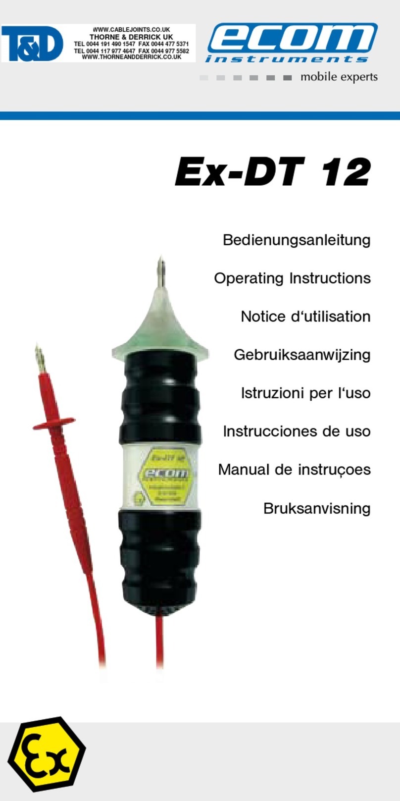
Ecom Ex-DT 12 User manual

1
Zone 1
BEDIENUNGSANLEITUNG
OPERATING INSTRUCTIONS
MODE D'EMPLOI
INSTRUCCIONES DE USO
Ex-DT 12

2 3
Deutsch Seite 3
English Page 20
Français Page 35
Español Página 51

4 5
Inhaltsverzeichniss
1. Anwendung 5
2. Sicherheitshinweise 5
3. Fehler und unzulässige Belastung 5
4. Sicherheitsvorschriften 6
5. Ex-Daten 7
6. Technische Daten 7
7. Funktionsbeschreibung 8
8. Reparatur 12
9. Reinigung und Wartung 12
10. Entsorgung 12
11. Garantie und Haftung 13
12. EG-Konformitätserklärung 15
13. EG-Baumusterprüfbescheinigung 17
Hinweis:
Die jeweils aktuelle Bedienungsanleitung, die
EG-Konformitätserklärung und das Ex-Zertifikat können
auf der jeweiligen Produktseite unter www.ecom-ex.com
heruntergeladen oder direkt beim Hersteller angefordert
werden.
1. Anwendung
Der Ex-DT 12 ist ein Vielfachprüfgerät zur Abschätzung von
Widerständen, Kapazitäten und Induktivitäten für explosi-
onsgefährdete Bereiche der Zone 2 und 1 nach Richtlinie
1999/92/EG (ATEX 137).
Die Anzeige erfolgt durch optische und akustische Signale.
2. Sicherheitshinweise
Die vorliegende Bedienungsanleitung enthält
Informationen und Sicherheitshinweise, die für eine sichere
Funktionsweise unter den beschriebenen Bedingungen
unbedingt zu berücksichtigen sind.
Eine Nichtbeachtung dieser Informationen und Hinweise
kann gefährliche Folgen haben oder gegen Vorschriften
verstoßen.
Vor dem Gebrauch des Geräts ist die Bedienungsanleitung
aufmerksam zu lesen!
Im Zweifelsfall (in Form von Übersetzungs- oder
Druckfehlern) gilt die deutsche Bedienungsanlei-tung.
3. Fehler und unzulässige Belastungen
Sobald zu befürchten ist, dass die Gerätesicherheit beein-
trächtigt wird, muss das Gerät außer Betrieb genommen
und unverzüglich aus dem Ex-Bereich entfernt werden.
Die unbeabsichtigte Wiederinbetriebnahme muss verhin-
dert werden.
Wir empfehlen, das Gerät dann zu einer Überprüfung an
den Hersteller zu schicken.
Die Gerätesicherheit kann z.B. gefährdet sein, wenn:
- am Gerät Beschädigungen sichtbar sind.
- an der Verbindungsleitung Beschädigungen sichtbar sind.
- das Gerät unsachgemäßen Belastungen ausgesetzt
wurde.

6 7
- das Gerät unsachgemäß gelagert wurde.
- das Gerät Transportschäden erlitten hat.
- Gerätebeschriftungen unleserlich sind.
- Fehlfunktionen auftreten.
- die zulässigen Grenzwerte überschritten sind.
4. Sicherheitsvorschriften
4.1 Allgemeine Vorschriften
Die Benutzung des Geräts setzt beim Anwender die
Beachtung der üblichen Sicherheitsvorschriften und das
Lesen des Zertifikates voraus, um Fehlbedienungen am
Gerät auszuschließen.
Folgende Sicherheitsvorschriften müssen beachtet wer-
den:
- Im Ex-Bereich nur an spannungsfreien Kreisen messen.
- Das Gerät darf innerhalb des Ex-Bereiches nicht geöffnet
werden.
- Die Batterien dürfen nur außerhalb des Ex-Bereiches
gewechselt werden.
- Das Mitführen von zusätzlichen Batterien ist im
Ex-Bereich nicht zulässig.
- Es dürfen nur die in der Bedienungsanleitung aufge-
führten typgeprüften Batterien eingesetzt werden.
- Es darf nur von ecom instruments GmbH zugelassenes
Zubehör verwendet werden.
- Bei Beschädigung der Leitungsisolierung und
Prüfspitzen ist das Gerät unverzüglich außer w
Betrieb zu nehmen.
- Die maximal zulässigen Umgebungstemperaturen sind
einzuhalten.
- Es ist sicherzustellen, dass das Gerät nicht in Zone 0
eingebracht wird.
4.2 Besondere Sicherheitsvorschriften
Um Verletzungen zu vermeiden, wird empfohlen, bei
Nichtgebrauch oder Lagerung des Gerätes immer die mit-
gelieferten Schutzkappen auf die Prüfspitzen aufzustecken.
4.3 Einsatz an Stromkreisen außerhalb des ww
Ex-Bereichs
Bei Betrieb/Einsatz an Stromkreisen außerhalb
des Ex-Bereichs ist darauf zu achten, dass die zuläs-
sigen Maximalwerte nicht überschritten werden
(Eigenverantwortung des Nutzers).
5. Ex-Daten
EG – Baumusterprüf-
bescheinigung- Nr.: TÜV 03 ATEX 2120
Ex-Kennzeichnung:
†
II 2G Ex ia IIC T4
Zugelassen für Zone 2 und 1, Gerätegruppe II,
Explosionsgruppe IIC, explosionsgefährdete Gase,
Dämpfe oder Nebel; Temperaturklasse T4
.
6. Technische Daten
Umgebungstemperatur Ta: -20 ... +50°C
Lagertemperatur: -20 ... +50°C
Widerstandsprüfung: ca. 10Ω - 450kΩ
Induktivitätsprüfung: 10mH – 1H
Kapazitätsprüfung: 0,5µF – 1000µF
Diodentest: 2 Diodenstrecken
Max. äußere Induktivität: 1H
Max. äußere Kapazität: 1000µF
Max. Fehler-Ausgangsstrom I0: 5mA
Max. Fehler-Ausgangsspannung U0:3,3V
Max. Fremdspannungsfestigkeit
außerhalb Ex-Bereich: Um= 420V
Stromversorgung: 2 x LR03 nach IEC
(siehe Tabelle mit typgeprüften Batterien)

8 9
Tabelle mit typgeprüften Batterien:
Hersteller
Typ
Varta LR03 Alkaline Universal No.4003
Duracell LR03 Alkaline
Ralston Energy
Systems SA LR03 Alkaline Energizer
GP LR03 Super Alkaline Battery
Betriebsdauer: ca. 20h (Dauerbetrieb)
Anzeige optisch: über 4 x LED (in Prüfspitze)
Anzeige akustisch: über Lautsprecher
Abmessung Prüfspitze: 50 x 175 mm (ø x l) (Minuspol)
Gesamtlänge: ca. 1,40 m
(Prüfspitze-Prüfspitze)
Gewicht: ca. 200g (mit Batterien)
CE- Kennzeichnung: 00102
7. Funktionsbeschreibung / Bedienungshinweise
Bitte lesen Sie diese Bedienungsanleitung sorg-
fältig durch, damit Sie alle Funktionen Ihres
Ex-DT 12 kennen und nutzen können.
Lesen Sie zu Ihrer Sicherheit und Information die Hinweise
auf den folgenden Seiten!
7.1 Inbetriebnahme
Führen Sie vor jedem Einsatz im Ex-Bereich einen
Funktionstest durch. Dazu schließen Sie beide Prüfspitzen
kurz. Dadurch entsteht der sogenannte Kurzschlusston
und die Leuchtdioden im Prüfkopf leuchten hell auf.
Ertönt der Kurzschlusston laut und klar, ist die
Batteriespannung ausreichend. Ist dies bei neuen Batterien
nicht der Fall, sollte das Gerät zur Überprüfung ins Werk
eingeschickt werden.
Die Batterien befinden sich werkseitig im Gerät.
7.2 Wechsel der Batterien
Führen Sie vor jedem Einsatz einen Funktionstest durch.
Dazu schließen Sie beide Prüfspitzen kurz. Dadurch
entsteht der sogenannte Kurzschlusston und die
Leuchtdioden im Prüfkopf leuchten hell auf.
Ertönt der Kurzschlusston laut und klar, ist die
Batteriespannung ausreichend. Ist dies nicht der Fall,
müssen die Batterien gewechselt werden. Es empfiehlt
sich, alle 2 Batterien auf einmal zu wechseln.
Es dürfen nur Batterien des entsprechend zugelassenen
Typs eingesetzt werden (siehe Tabelle mit typgeprüften
Batterien unter Punkt 6. Technische Daten).
Zum Batteriewechsel muss zuerst die Sicherungsschraube
mit einem geeigneten Innensechskantschlüssel entfernt
werden. Danach kann die Griffhülse des Durchgangstesters
nach hinten abgezogen und die Batterien entnommen wer-
den. Beim Einsetzen der neuen Batterien bitte Polarität
beachten.
Die Kontakte der neuen Batterien und der Hal-terungen
sollten vor dem Einsetzen gereinigt werden. Nachdem die
Batterien eingesetzt wurden, wird die Griffhülse wieder auf
die Leuchtspitze aufgeschoben. Dabei ist zu beachten, dass
die rote Verbindungsleitung nicht im Inneren der Hülse
eingeklemmt wird (Leitung beim Vorschieben der Hülse
leicht straff halten).
Danach kann die Griffhülse wieder mit der
Sicherungsschraube gesichert werden.
Batteriewechsel
- Immer alle Batterien gleichzeitig auswechseln.
- Auf richtige Polarität achten.
- Verbrauchte Batterien sach- und umweltgerecht entsorgen!
7.3 Durchgangsprüfung an spannungsfreien Objekten
Mit dem Ex-DT 12 kann man schnell und sicher prü-

10 11
fen, ob ein Gerät, ein Bauteil, eine Leitung oder sonst
eine Verbindung leitfähig ist. Dazu müssen die beiden
Prüfspitzen mit den entsprechen Anschlüssen des
Prüflings verbunden werden. Wenn Durchgang vorhanden
ist, ertönt der Ex-DT 12 und der Leuchtindikator leuchtet
gleichzeitig auf.
Die Tonhöhe ist abhängig vom Widerstand des Prüflings
und verhält sich dazu umgekehrt proportional, d.h. je
kleiner der Widerstand, desto mehr ähnelt der Ton dem
Kurzschlusston (siehe Punkt 7.1).
7.4 Prüfen / Abschätzen von Widerständen
Zur Widerstandsprüfung bzw. Abschätzung müs-
sen die Prüfspitzen des Ex-DT 12 an das zu prüfen-
de Objekt gehalten werden. Der Kurzschlusston kann
als Referenzton betrachtet werden.
Je größer der abzuschätzende Widerstand, desto tiefer fällt
die Tonfrequenz des Messtons unter die des Referenztons.
Bereiche, siehe Punkt 6. Technische Daten.
7.5 Prüfen / Abschätzen von Kapazitäten
Kondensatoren können im spannungslosen (entladenen)
Zustand auf Funktion geprüft werden. Zu unterschei-
den sind hier Folien-(ungepolt), Elektrolyt-(gepolt) und
Tantalkondensatoren (gepolt).
Der Prüfbereich für Kondensatoren beginnt ab 0,5µF auf-
wärts (siehe Punkt 6. Technische Daten).
Beim Prüfen hören Sie während der Aufladezeit des
Kondensators einen abfallenden Signalton,
der allmählich ganz verstummt. Je größer die Kapazität
des Kondensators, desto länger ist die Abfallzeit des
Signaltons.
Ertönt beim Prüfen des Kondensators ein Dauerton ähnlich
dem Kurzschlusston, so ist der Kondensator defekt (inter-
ner Kurzschluss).
Ertönt beim Prüfen des Kondensators kein Ton, so ist
entweder die Kapazität unter dem möglichen Prüfbereich,
oder es gibt interne Unterbrechungen.
Bitte beachten sie den max. Anschlusswert eines
Kondensators im Ex-Bereich!
7.6 Prüfen / Abschätzen von Induktivitäten
Zusätzlich zu dem ohmschen Innenwiderstand einer
Induktivität wird zugleich auch die Induktivität abgeschätzt.
Bei steigender Induktivität fällt die Tonfrequenz des
Messtons unter den Referenzton.
Bitte beachten sie den max. Anschlusswert einer
Induktivität im Ex-Bereich!
7.7 Prüfen / Abschätzen von Dioden
Beim Diodentest ist die Polarität zu beachten!
Ist die rote Prüfspitze (Pluspol) mit der Anode und die
schwarze Prüfspitze (Minuspol) mit der Kathode verbun-
den, so wird die Diode in Durchlassrichtung geprüft. Hier
muss die Tonhöhe ähnlich dem Kurzschlusston sein.
Prüft man nun in Sperrrichtung und es ist kein Ton hörbar,
so ist die Diode in Ordnung.
7.8 Messungen an nicht-eigensicheren Stromkreisen
Folgendes ist zu beachten:
Nach dem Einsatz an nicht eigensicheren Stromkreisen ist
eine Funktionskontrolle (siehe Punkt 7.1 Inbetriebnahme)
des Durchgangstesters vorzunehmen und eine Verweilzeit
von 5 Minuten einzuhalten, bevor der Durchgangstester in
explosionsgefährdete Bereiche eingebracht wird.

12 13
8. Reparatur
Bei Reparaturen gelten jeweils unterschiedliche natio-
nale Bestimmungen und Richtlinien. Wir empfehlen die
Reparatur bei ecom instruments, Deutschland, da eine
sicherheitstechnische Überprüfung bei einer Reparatur
erforderlich ist.
9. Reinigung, Wartung und Lagerung
Gerät nur mit einem geeigneten Tuch oder Schwamm rei-
nigen. Verwenden Sie zur Reinigung keine Lösungs- oder
Scheuermittel.
Es wird empfohlen, die Funktion und Genauigkeit des
Geräts alle zwei Jahre vom Hersteller überprüfen zu
lassen.
Bei längerer Lagerung sind die Batterien aus dem Gerät
zu entnehmen.
Zulässige Lagertemperaturen –20°C bis +50°C nicht unter-
bzw. überschreiten!
10. Entsorgung
Elektroaltgeräte sowie „historische“ Elektroaltgeräte von
der Firma ecom instruments GmbH werden zu unseren La-
sten der Entsorgung zugeführt und nach der europäischen
Richtlinie 2002/96/EG und dem deutschen Elektro-Gesetz
vom 16.03.2005 kostenfrei entsorgt. Der Versand der Geräte
zu ecom instruments GmbH geht auf Kosten des Versen-
ders.
Nach Artikel 1, §18 und Artikel 2 des Gesetzes zur Neu-
regelung der abfallrechtlichen Produktverantwortung für
Batterien und Akkumulatoren vom 25. Juni 2009 sind wir zu
folgenden Hinweisen verpflichtet.
Ihr Gerät enthält eine alkalische Batterie.
Sind die Batterien „leer“ dürfen Sie nicht in den normalen
Müll oder Hausmüll. Altbatterien enthalten möglicherwei-
se Schadstoffe, die Umwelt und Gesundheit schaden kön-
nen. Bitte geben Sie die Batterien zurück. Die Rückgabe ist
unentgeltlich und gesetzlich vorgeschrieben. Bitte werfen
Sie nur entladene Batterien in die aufgestellten Behälter.
Achtung: Die im Gerät eingesetzte Batterie birgt eine Feu-
ergefahr und die Gefahr von chemischen Verletzungen bei
nicht ordnungsgemäßem Einsatz. Weder die Batterie noch
die Batteriezellen dürfen geöffnet oder demontiert, nicht
über 100°C erhitzt oder verbrannt werden.
Im Entsorgungsfall kann die Batterie wie in Punkt (7.2) be-
schrieben entnommen werden. Im Übrigen gelten die oben
genannten Entsorgungsvorschriften für Altgeräte.
Alle Batterien werden wieder verwertet. So lassen sich
wertvolle Rohstoffe wie Eisen, Zink oder Nickel wieder ge-
winnen.
Das Symbol (hier Icon Mülltone einfügen) hat folgende Be-
deutung: Batterien und Akkus dürfen nicht in den normalen
Müll oder Hausmüll.
11. Garantie und Haftung
Für dieses Produkt gewährt die ecom instruments GmbH
laut den allgemeinen Geschäftsbedigungen eine Garantie
von zwei Jahren auf Funktion und Material unter den an-
gegebenen und zulässigen Betriebs- und Wartungsbedin-
gungen. Ausgenommen hiervon sind alle Verschleißteile
(z.B. Batterien, Antennen, Clips, Handschlaufen, etc).
Diese Garantie erstreckt sich nicht auf Produkte, die un-
sachgemäß verwendet, verändert, vernachlässigt, durch
Unfälle beschädigt oder anormalen Betriebsbedingungen
sowie einer unsachgemäßen Handhabung ausgesetzt wur-
den.

14 15
Forderungen auf Gewährleistungen können durch Einsen-
den des defekten Geräts geltend gemacht werden. Repa-
raturen, neues Einjustieren oder Austauschen des Gerätes
behalten wir uns vor.
Die voranstehenden Garantiebestimmungen sind das ein-
zige und alleinige Recht auf Schadenersatz des Erwerbers
und gelten ausschließlich und an Stelle von allen anderen
vertraglich oder gesetzlichen Gewährleistungspflichten.
ecom instruments GmbH übernimmt keine Haftung für
spezielle, unmittelbare, mittelbare, Begleit- oder Folge-
schäden sowie Verluste einschließlich des Verlusts von
Daten, unabhängig davon, ob sie auf Verletzung der Ge-
währleistungspflicht, rechtmäßige oder unrechtmäßige
Handlungen, Handlungen in gutem Glauben sowie andere
Handlungen zurückzuführen sind.
Falls in einigen Ländern die Begrenzung einer gesetzlichen
Gewährleistung sowie der Ausschluss oder Begrenzung
von Begleit- oder Folgeschäden nicht zulässig ist, könnte
es sein, dass die obengenannten Einschränkungen und
Ausschlüsse nicht für jeden Erwerber gelten. Sollte ir-
gendeine Klausel dieser Garantiebestimmungen von einem
zuständigen Gericht für unwirksam oder nicht durchsetz-
bar befunden werden, so bleiben die Wirksamkeit oder
Erzwingbarkeit irgendeiner anderen Bedingung dieser Ga-
rantiebestimmungen von einem solchen Spruch unberührt.
12. EG Konformitätserklärung
ecom instruments GmbH | Industriestraße 2 | 97959 Assamstadt | Germany
Tel.: +49 62 94 / 42 24-0 | Fax: +49 62 94 / 42 24-100 | E-Mail: [email protected] | www.ecom-ex.com
1/2
EG-Konformitätserklärung / EC-Declaration of Conformity
Déclaration de conformité CE
nach Richtlinie 94/9/EG (ATEX)
according to directive 94/9/EC (ATEX)
selon les directives 94/9/CE (ATEX)
Wir, ecom instruments GmbH, erklären in alleiniger Verantwortung, dass unser Produkt auf welches sich diese Erklärung
bezieht, den nachfolgenden Daten, Richtlinien und Normen entspricht:
We, ecom instruments GmbH, declare under our sole responsibility, that the product to which this declaration relates, is
in accordance with the provision of the following standards, directives and norms:
Nous, ecom instruments GmbH, déclarons sous notre seule responsabilité, que le produit pour lequel cette déclaration se
rapporte, est conforme à la disposition des normes et des directives suivantes:
Name & Anschrift des Herstellers innerhalb der europäischen Gemeinschaft
Name & address of the manufacturer in the EC
Nom et adresse du fabricant dans l‘Union Européenne
ecom instruments GmbH
Industriestraße 2
97959 Assamstadt
Germany
Beschreibung der Geräte
Description of the devices
Description des appareils
Durchgangstester
continuity tester
Testeur de continuité
Typ/Type: Ex-DT 12
Ex-Kennzeichnung
Ex-designation
Marquage Ex
II 2G Ex ia IIC T4
EG-Baumusterprüfbescheinigung
EC-Type Examination Certifi cate
Déclaration de conformité CE
TÜV 03 ATEX 2120
Zertifi zierungsstelle
Notifi ed body
Organisme notifi é
TÜV NORD CERT GmbH & Co. KG
TÜV CERT-Zertifi zierungsstelle
Am TÜV 1
30519 Hannover, Germany
identifi cation number: 0032
Name & Anschrift der überwachenden Stelle
a) Qualitätssicherungssystem ISO 9001
Name & address of auditing body
a) Quality Management System according to ISO 9001
Nom et adresse de l‘organisme certifi é
a) Système d‘assurance qualité selon ISO 9001
DEKRA Certifi cation GmbH
Handwerkstraße 15
70565 Stuttgart
Germany

16 17
Weitere Details zur Konformitätserklärung nden Sie
unter folgender Internet-Adresse:
www.ecom-ex.com im Downloadbereich.
ecom instruments GmbH | Industriestraße 2 | 97959 Assamstadt | Germany
Tel.: +49 62 94 / 42 24-0 | Fax: +49 62 94 / 42 24-100 | E-Mail: [email protected] | www.ecom-ex.com
2/2
2350ME03A00
WEEE-Reg.-Nr.: DE 934 99306
Name & Anschrift der überwachenden Stelle
b) Qualitätssicherungssystem der Produktion gemäß Richtlinie 94/9/EG
(ATEX)
Name & address of auditing body
b) Quality Management System of production according to directive 94/9/EC
(ATEX)
Nom et adresse de l‘organisme certifi é
b) Système d‘assurance qualité pour la fabrication selon la directive 94/9/EC
(ATEX)
Physikalisch-Technische Bundesanstalt
Bundesallee 100
38116 Braunschweig
Germany
Kenn-Nummer / Identifi cation number /
Numéro d‘identifi cation: 0102
Angewandte harmonisierte Standards
Applied harmonized standards
Standards harmonisés appliqués
EN 60079-0: 2006
EN 50020: 2002
EN 61326: 1997
EN 61000-4-1: 2000
EN 61000-4-2: 1995
EN 61000-4-3: 1996
EN 61000-4-4: 1995
EN 61000-4-5: 1995
EN 61000-4-6: 1996
EN 61000-4-7: 1993
EN 61000-4-8: 1993
EN 61000-4-9: 1993
EN 61000-4-10: 1993
EN 61000-4-11: 1994
EN 61000-4-12: 1995
Angewandte europäische Richtlinien
Applied European directives
Directives générales européennes appliquées
ATEX directive: 94/9/EC
EMC-directive: 89/336/EEC
ecom instruments GmbH
Assamstadt 14. 05. 2014
Jörg Hartleb
Chief Operating Officer | Member of Executive Board
Unterzeichnet /
signed
13. EG-Baumusterprüfbescheinigung

18 19

20 21
Table of contents
1. Application 21
2. Safety precautions 21
3. Errors and load restrictions 21
4. Safety regulations 22
5. Ex-data 22
6. Technical data and specifications 23
7. Functional description 24
8. Repairs 27
9. Cleaning, maintenance and storage 27
10. Disposal 27
11. Warranty and liability 28
12. EC-Declaration of conformity 30
13. EC-type-examination certificate 32
Note:
The current operating instructions, the Declaration of EC
Conformity and the ex-certificate are available for down-
load from the relevant product page under www.ecom-ex.
com, or alternatively they can be requested directly from
the manufacturer.
1. Application
The Ex-DT 12 is a multi-purpose testing device for calcula-
ting resistances, capacities and inductance for potentially
explosive areas of Zones 2 and 1 in accordance with direc-
tive 1999/92/EC (ATEX 137). Reading are indicated in the
form of visual and acoustic signals.
2. Safety precautions
This Owner’s Manual contains information and safety regu-
lations which must be followed to ensure safe and reliable
operation of the device under the described conditions.
Failure to follow the information and instructions contained
in this manual can have dangerous consequences or may
contravene applicable legislation.
Please take the time to carefully read through the owner’s
manual before you start using the device. In case of any
doubt (in form of translation or printing errors) the German
language operating instructions shall apply.
3. Errors and load restrictions
If there is any risk that the safety or integrity of the device
has been compromised, then the device must be taken out
of operation immediately and removed from the ex-area
without delay. Action must be taken to prevent the device
from being accidentally taken into operation again.
We recommend that the device should be sent to the
manufacturer to be examined.
The safety and reliability of the device may be at risk if,
for example:
- visible damage is evident on the device,
- visible damage is evident on the connecting cable,
- the device has been subjected to excessive loads for
which it is not designed,
- the device has been improperly stored,
- the device has been damaged in transit,
- inscriptions or lettering on the device are illegible,
- malfunctions occur,
- permitted tolerances or threshold values are exceeded.

22 23
4. Safety regulations
4.1 General safety regulations
Use of the explosion-proof Ex-DT 12 assumes that the
operator complies with conventional safety regulations and
has reas the certificate in order to eliminate faulty opera-
tion of the unit. The following additional safety regulations
must also be observed:
- In the ex-area, take measurements only on idle circuits.
- The device must not be opened within the ex-area.
- The batteries must only be changed outside the ex-area.
- Additional or spare batteries must not be carried in the
ex-area.
- Only the batteries listed in the Owner’s Manual wmust be
used, as these batteries are typeapproved.
- Only accessories approved by ecom instruments GmbH
may be used.
- If the cable insulation or test probe become damaged,
the device must be taken out of operation immediately.
- The maximum permitted ambient temperatures wmust
be respected.
- It must be ensured that the unit is not taken into zone 0.
4.2 Special safety regulations
In order to avoid injury, it is advisable to fit the supplied
protective caps over the test probes when the device is not
in use or being stored.
4.3 Use on electrical circuits outside the ex-area
When operating/using the device on electrical circuits
outside the ex-area, ensure that the permitted maximum
values are not exceeded (responsibility of the user).
5. Ex-data
EC-type-examination
certificate no.: TÜV 03 ATEX 2120
Ex-marking:
†
II 2 G Ex ia IIC T4
Approved for Zones 2 and 1, device group II; explosion
group IIC; potentially explosive gases, vapours or mist,
temperature class T4.
6. Technical data and specifications
Ambient
temperature Ta: -20 ... +50°C
Storage temperature: -20 ... +50°C
Resistance: approx. 10Ω - 450kΩ
Inductance test: 10mH – 1H
Capacitance test: 0,5µF – 1000µF
Diode test: 2 diode sections
Max. external inductance: 1H
Max. external capacitance: 1000µF
Max. fault output current I0: 5mA
Max. fault output voltage U0: 3.3V
Max. external electrical
strength outside of ex-area: Um= 420V
Power supply: 2 x LR03 acc. to IEC
(see Table listing type-
approved batteries)
Table listing type-approved batteries:
Manufacturer Type
Varta LR03 Alkaline Universal No.4003
Duracell LR03 Alkaline
Ralston Energy
Systems SA LR03 Alkaline Energizer
GP LR03 Super Alkaline Battery
Duration of operation: approx. 20h (continuous)
Visual indication: 4 x LED (in test probe)
Acoustic indication: loudspeaker
Test probe dimensions: 50 x 175 mm (ø x l)
(Negative terminal)
Overall length: approx. 1,40 m
(test probe to test probe)
Weight: approx. 200g
(including batteries)
CE mark: 00102

24 25
7. Functional description / operating information
Please take the time to carefully read through this Owner’s
Manual to ensure that you are familiar with all of the
functions of your Ex-DT 12 and know how to use all of the
functions.
For your own safety and information please read through
the information on the following pages.
7.1 Getting started
Run a function test each time you use the device in the
ex-area. To do this, short circuit both test probes. You will
hear the so-called short circuit signal and the LEDs in the
test head illuminate.
If the short circuit signal is loud and clear, the battery
power is adequate. If this is not the case when new bat-
teries are fitted, send the device back to the factory for
checking.
Batteries are factory-fitted.
7.2 Replacing the batteries
Run a function test each time you use the device. To do
this, short circuit both test probes. You will hear the so-
called short circuit signal and the LEDs in the test head
illuminate.
If the short circuit signal is loud and clear, the battery
power is adequate. If this is not the case, the batteries
need replacing. It is advisable to replace both batteries at
the same time.
Only approved batteries may be used (see Table listing
type-approved batteries under Item 6. Technical Data).
Before the batteries can be replaced, remove the securing
screw using a suitable screw driver. The grip sleeve of the
continuity tester can now be pulled backwards and the
batteries removed. Ensure correct polarity when inserting
new batteries.
The contacts of the new batteries and the holders should
be cleaned before fitting. Once the batteries have been
replaced, slide the grip sleeve back onto the light sensor.
Please ensure that the red connecting cable does not
become trapped inside the grip sleeve (keep a firm hold of
the cable when sliding in the sleeve).
The grip sleeve can now be refastened with the securing
screw.
Battery replacement
- Always replace all of the batteries together.
- Make sure that the polarity of the inserted batteries is
correct.
- Please ensure that all used batteries ar properly disposed
of in an environmentallyfriendly manner.
7. 3 Continuity testing of idle objects
The Ex-DT 12 can be used to test swiftly and safely whether
a device, a component, a cable or connection is conductive.
This requires both test probes to be connected to the
appropriate ports on the specimen. If continuity is detected,
the Ex-DT 12 emits an acoustic signal and the indicator
lamp illuminates. The pitch depends on the resistance of
the specimen and has a proportionally reverse pattern, i.e.
the smaller the resistance, the more the sound resembles
that of the short circuit (see Item 7.1).
7.4 Testing / calculating resistances
To test or measure resistances, the test sensors of the
Ex-DT 12 must be held on the object being tested. The short
circuit signal can be considered a reference signal.
The greater the resistance to be measured, the further
the frequency of the measuring signal drops below the
reference signal. For ranges, see Item 6 – Technical Data.
7.5 Testing / calculating capacitance
Capacitors can be tested for correct functioning when idle
(discharged). A distinction must be drawn here between
film (unpolarized), electrolyte (polarized) and tantalum
capacitors (polarised).
The testing range for capacitors is upwards from 0.5µF (see
Item 6 – Technical Data).
When charging-up the capacitor during the test, you will

26 27
hear a sloping signal, which gradually dies out. The gre-
ater the capacitor’s capacitance, the longer the fall time
of the signal.
If while the capacitor is being tested, a continuous signal
similar to the short-circuit signal sounds, the capacitor is
faulty (internal short circuit).
If no signal sounds while a capacitor is being tested, either
the capacitance is below the practical test range or an
internal interruption has occurred.
Please respect the max. connection value of a capacitor
in the ex-area!
7.6 Testing / calculating inductance
Besides the active internal resistance of an inductance, the
inductance itself is also measured. As inductance incre-
ases, the frequency of the measured tone drops below that
of the reference tone.
Please respect the max. connection value of an inductance
in the ex-area!
7.7 Testing / measuring diodes
Ensure correct polarity when performing the diode test!
If the red test probe (positive terminal) is connected to the
anode and the black test probe (negative terminal) is con-
nected to the cathode, the diode is tested in the continuity
direction. In this case, the pitch must approximate that of
the short circuit signal.
If the same test is now performed in the no continuity
direction and no signal is heard, the diode is in sound
working order.
7.8 Measurements on non-intrinsically safe circuits
Please note the following:
After being used on non-intrinsically safe electrical cir-
cuits, the continuity tester must be subjected to a function
test (see Item 7.1 – Getting started) and a dwell time of 5
minutes must pass before the continuity tester can be used
in potentially explosive areas.
8. Repairs
The national regulations and guidelines for repairs vary
from country to country. We therefore recommend that re-
pairs are conducted by ecom instruments GmbH to ensure
a safety inspection is implemented.
9. Cleaning, maintenance and storage
Only use a suitable cloth or sponge to clean the device.
Do not use solvents or abrasive cleaning agents to clean
the device.
We recommended having the function and the accuracy of
the device checked by the manufacturer every two years.
The batteries should be taken out of the device if it is to be
stored for a long time.
The storage temperature should be within the permitted
ranged of -20°C to +50°C.
10. Disposal
Old electrical devices as well as „historical“ old electrical
devices from ecom instruments GmbH are supplied for
disposal at our expense and disposed of free of charge in
accordance with European Directive 2002/96/EC and the
German electrical law of 16/03/2005. The costs associated
with returning devices to ecom instruments GmbH are to be
borne by the sender.
In accordance with “Directive 2006/66/EC on batteries and
accumulators and waste batteries” we are obligated to pro-
vide you with the following information:
Your device contains an alkaline battery.
Depleted batteries should never be disposed of along with
normal or household waste. Old batteries can contain
harmful substances that are hazardous to health and da-
maging to the environment. Please return the batteries.
Return is free of charge and required by law. Please only
dispose of discharged batteries in the designated contai-
ners.

28 29
Note: The battery used in this unit poses a fire hazard and
can cause chemical injuries if it is used improperly. Neit-
her the battery nor the battery cells should be opened or
disassembled and they should not be burned or exposed to
temperatures exceeding 100°C.
If the battery needs to be disposed of, it can be removed as
described under point (7.2). The disposal regulations speci-
fied above are also applicable for old devices.
All batteries can be recycled. Precious raw materials such
as iron, zinc and nickel can therefore be reused.
The symbol has the following meaning: Batteries and re-
chargeable batteries should not be disposed of along with
normal or household waste.
11. Warranty and liability
In accordance with our general terms and conditions
ecom instruments GmbH provides a warranty for this
product for a period of two years regarding its func-
tion and material under the specied and permitted
operating and maintenance conditions. This excludes
all parts that are subject to wear and tear (e.g. bat-
teries).
This warranty does not extend to products that are
used improperly, have been modied, neglected, da-
maged in accidents or exposed to abnormal opera-
ting conditions and inappropriate handling.
Any claims under the warranty can be invoked by re-
turning the defective equipment to the manufacturer.
We reserve the right to repair, adjust or exchange the
device.
The aforementioned warranty conditions are the sole
and only right of the purchaser to compensation,
are exclusively valid and replace all other contract
or legal warranty obligations. ecom instruments
GmbH assumes no liability for special, direct, indi-
rect, accompanying or consequential damage as well
as losses including the loss of data, independent of
whether it was caused by violation of the warranty ob-
ligation, lawful or unlawful action, action in good faith
or any other action.
If the limitation of a legal warranty as well as the ex-
clusion or limitation of accompanying or consequen-
tial damage is not permissible in certain countries, it
may be that the aforementioned limitations and ex-
clusions are not valid for every purchaser. Should any
such clause of these warranty conditions be declared
ineffective or unenforceable by a competent court,
then the effectiveness or enforceability of any of the
other conditions of these warranty conditions shall
remain unaffected by such a judgment.

30 31
12. EC Declaration of Conformity
ecom instruments GmbH | Industriestraße 2 | 97959 Assamstadt | Germany
Tel.: +49 62 94 / 42 24-0 | Fax: +49 62 94 / 42 24-100 | E-Mail: [email protected] | www.ecom-ex.com
1/2
EG-Konformitätserklärung / EC-Declaration of Conformity
Déclaration de conformité CE
nach Richtlinie 94/9/EG (ATEX)
according to directive 94/9/EC (ATEX)
selon les directives 94/9/CE (ATEX)
Wir, ecom instruments GmbH, erklären in alleiniger Verantwortung, dass unser Produkt auf welches sich diese Erklärung
bezieht, den nachfolgenden Daten, Richtlinien und Normen entspricht:
We, ecom instruments GmbH, declare under our sole responsibility, that the product to which this declaration relates, is
in accordance with the provision of the following standards, directives and norms:
Nous, ecom instruments GmbH, déclarons sous notre seule responsabilité, que le produit pour lequel cette déclaration se
rapporte, est conforme à la disposition des normes et des directives suivantes:
Name & Anschrift des Herstellers innerhalb der europäischen Gemeinschaft
Name & address of the manufacturer in the EC
Nom et adresse du fabricant dans l‘Union Européenne
ecom instruments GmbH
Industriestraße 2
97959 Assamstadt
Germany
Beschreibung der Geräte
Description of the devices
Description des appareils
Durchgangstester
continuity tester
Testeur de continuité
Typ/Type: Ex-DT 12
Ex-Kennzeichnung
Ex-designation
Marquage Ex
II 2G Ex ia IIC T4
EG-Baumusterprüfbescheinigung
EC-Type Examination Certifi cate
Déclaration de conformité CE
TÜV 03 ATEX 2120
Zertifi zierungsstelle
Notifi ed body
Organisme notifi é
TÜV NORD CERT GmbH & Co. KG
TÜV CERT-Zertifi zierungsstelle
Am TÜV 1
30519 Hannover, Germany
identifi cation number: 0032
Name & Anschrift der überwachenden Stelle
a) Qualitätssicherungssystem ISO 9001
Name & address of auditing body
a) Quality Management System according to ISO 9001
Nom et adresse de l‘organisme certifi é
a) Système d‘assurance qualité selon ISO 9001
DEKRA Certifi cation GmbH
Handwerkstraße 15
70565 Stuttgart
Germany
Further details regarding the declaration of confor-
mity can be found at the following address:
http://www.ecom-ex.com in the download area.
ecom instruments GmbH | Industriestraße 2 | 97959 Assamstadt | Germany
Tel.: +49 62 94 / 42 24-0 | Fax: +49 62 94 / 42 24-100 | E-Mail: [email protected] | www.ecom-ex.com
2/2
2350ME03A00
WEEE-Reg.-Nr.: DE 934 99306
Name & Anschrift der überwachenden Stelle
b) Qualitätssicherungssystem der Produktion gemäß Richtlinie 94/9/EG
(ATEX)
Name & address of auditing body
b) Quality Management System of production according to directive 94/9/EC
(ATEX)
Nom et adresse de l‘organisme certifi é
b) Système d‘assurance qualité pour la fabrication selon la directive 94/9/EC
(ATEX)
Physikalisch-Technische Bundesanstalt
Bundesallee 100
38116 Braunschweig
Germany
Kenn-Nummer / Identifi cation number /
Numéro d‘identifi cation: 0102
Angewandte harmonisierte Standards
Applied harmonized standards
Standards harmonisés appliqués
EN 60079-0: 2006
EN 50020: 2002
EN 61326: 1997
EN 61000-4-1: 2000
EN 61000-4-2: 1995
EN 61000-4-3: 1996
EN 61000-4-4: 1995
EN 61000-4-5: 1995
EN 61000-4-6: 1996
EN 61000-4-7: 1993
EN 61000-4-8: 1993
EN 61000-4-9: 1993
EN 61000-4-10: 1993
EN 61000-4-11: 1994
EN 61000-4-12: 1995
Angewandte europäische Richtlinien
Applied European directives
Directives générales européennes appliquées
ATEX directive: 94/9/EC
EMC-directive: 89/336/EEC
ecom instruments GmbH
Assamstadt 14. 05. 2014
Jörg Hartleb
Chief Operating Officer | Member of Executive Board
Unterzeichnet /
signed

32 33
13. EC-type-examination certificate
TRANSLATION
TRANSLATION
TRANSLATION

34 35
1.Addendum
to certificate number: TÜV 03 ATEX 2120
Device: Continuity tester Ex-DT12
Manufacturer: ecom Instruments GmbH
Address: Industriestr. 2
97959 Assamstadt
Order number: 8000554525
Date of issue: 22.05.2008
Changes:
The device is evaluated in line with a change in standards.
The electrical data and all other details remain unchanged for this addendum.
The device incl. this addendum fulfils the requirements of the following standards:
EN 60079-0:2006 EN 50020:2002
(16) The test documents are listed in test report No. 08 203 554525.
(17) Special conditions
no additional requirements
(18) Fundamental health and safety requirements
no additional requirements
TÜV NORD CERT GmbH, Langemarckstraße 20, 45141 Essen, accredited by the Central Authority of the Federal States for Safety
(ZLS), ID No. 0044. Assignee of TÜV NORD CERT GmbH & Co. KG ID No. 0032
Head of the certification body
Schwedt
Hanover branch, Am TÜV 1, 30519 Hannover, Tel.: +49 (0) 511 986-1455, Fax: +49 (0) 511 986-1590
P17-F-006 06-06 Page 1/1
TRANSLATION
TRANSLATION
TRANSLATION
TRANSLATION
TRANSLATION
TRANSLATION
TRANSLATION
TRANSLATION
TRANSLATION
TRANSLATION
TRANSLATION
TRANSLATION
TRANSLATION
TRANSLATION
TRANSLATION
TRANSLATION
TRANSLATION
TRANSLATION
The device is evaluated in line with a change in standards.
TRANSLATION
The device is evaluated in line with a change in standards.
TRANSLATION
TRANSLATION
The electrical data and all other details remain unchanged for this addendum.
TRANSLATION
The electrical data and all other details remain unchanged for this addendum.
TRANSLATION
TRANSLATION
The device incl. this addendum fulfils the requirements of the following standards:
TRANSLATION
The device incl. this addendum fulfils the requirements of the following standards:
TRANSLATION
TRANSLATION
EN 60079-0:2006 EN 50020:2002
TRANSLATION
EN 60079-0:2006 EN 50020:2002
TRANSLATION
TRANSLATION
The test documents are listed in test report No. 08 203 554525.
TRANSLATION
The test documents are listed in test report No. 08 203 554525.
TRANSLATION
TRANSLATION
TRANSLATION
TRANSLATION
TRANSLATION
no additional requirements
TRANSLATION
no additional requirements
TRANSLATION
TRANSLATION
TRANSLATION
(18) Fundamental health and safety requirements
TRANSLATION
(18) Fundamental health and safety requirements
TRANSLATION
TRANSLATION
no additional requirements
TRANSLATION
no additional requirements
TRANSLATION
TRANSLATION
TRANSLATION
TRANSLATION
TRANSLATION
TÜV NORD CERT GmbH, Langemarckstraße 20, 45141 Essen, accredited by the Central Authority of the Federal States for Safety
TRANSLATION
TÜV NORD CERT GmbH, Langemarckstraße 20, 45141 Essen, accredited by the Central Authority of the Federal States for Safety
TRANSLATION
(ZLS), ID No. 0044. Assignee of TÜV NORD CERT GmbH & Co. KG ID No. 0032
TRANSLATION
(ZLS), ID No. 0044. Assignee of TÜV NORD CERT GmbH & Co. KG ID No. 0032
TRANSLATION
TRANSLATION
TRANSLATION
Head of the certification body
TRANSLATION
Head of the certification body
TRANSLATION
TRANSLATION
TRANSLATION
Sommaire
1. Utilisation 36
2. Conseils de sécurité 36
3. Erreurs et efforts non admissibles 36
4. Consignes de sécurité 37
5. Caractéristiques Ex 38
6. Caractéristiques techniques 38
7. Description des fonctions 39
8. Réparations 43
9.
Nettoyage, entretien et stockage
43
10. Garantie et responsabilité 43
11. Élimination 44
12. Déclaration de conformité CE 46
13. Attestation d’examen CE de type 48
Remarque:
Le mode d'emploi actuel, le certificat de conformité CE et
le certificat de conformité Ex peuvent être téléchargés sur
la page produit correspondante à www.ecom-ex.com ou
demandées directement au fabricant.

36 37
1. Utilisation
Le EX-DT 12 est un appareil de contrôle multifonctions
permettant d’évaluer les résistances, les capacités
et les inductances pour les zones explosibles 2 et 1,
conformément à la directive 1999/92/CE (ATEX 137).
L’affichage est effectué à l’aide signaux opti-ques et
acoustiques.
2. Conseils de sécurité
Le présent mode d’emploi contient des informations et
des consignes de sécurité devant être impérativement
respectées pour un fonctionnement sûr dans les conditions
décrites.
Le non-respect de ces informations et consig-nes peut
avoir des conséquences dangereuses ou être contraire
aux directives.
Avant d’utiliser l’appareil, lire attentivement le mode
d’emploi!
En cas de doute (sous forme d‘erreurs de traduction ou
d‘impression), le mode d‘emploi allemand fait foi.
3. Erreurs et efforts non admissibles
Dès qu’il apparaît un doute sur la capacité de l’appareil
à assurer une sécurité totale, mettre l’appareil hors ser-
vice et le retirer immédiatement de la zone explosible.
Empêcher toute remise en service involontaire.
Nous recommandons de retourner l’appareil au fabricant
pour contrôle.
La sécurité de l’appareil peut par exemple être remise en
question si :
- des dommages sont visibles sur l’appareil,
- des dommages sont visibles sur le câble de connexion,
- l’appareil a été soumis à des efforts non conformes,
- l’appareil a été stocké de façon non conforme,
- l’appareil a subi des dommages lors du transport,
- les inscriptions sur l’appareil sont illisibles,
- des dysfonctionnements se produisent,
- les valeurs limites admissibles ont été dépassées.
4. Consignes de sécurité
4.1 Consignes générales
L’utilisateur de l’appareil protégé contre les explosions
suppose le respect des consignes de sécurité usuelles et
la lecture du certificat, afin d‘exclure tout risque de mau-
vaises manipulations. Les consignes de sécurité suivantes
doivent être respectées :
- Dans la zone explosible, effectuer les mesures wunique-
ment sur des circuits hors tension.
- Ne pas ouvrir l’appareil dans la zone explosible.
- Remplacer les piles uniquement hors de la zone explosible.
- Il est interdit d’amener des piles supplémentaires dans
la zone explosible.
- Utiliser exclusivement les piles homologuées menti-
onnées dans ce mode d’emploi.
- Utiliser exclusivement les accessoires autorisés par
ecom instruments GmbH.
- En cas d’endommagement de l’isolation du câble ou
des pointes de touche, mettre immédiatement l’appareil
hors service.
- Respecter les températures ambiantes maximales
admissibles.
-
S‘assurer que l‘appareil ne soit pas introduit dans
la zone 0
4.2 Consignes de sécurité particulières
Afin d’éviter les blessures, nous recommandons, en cas
de non-utilisation ou de stockage de l’appareil de toujours
munir les pointes de touche avec les capuchons de pro-
tection fournis.

38 39
4.3 Utilisation sur des circuits électriques en-dehors de
la zone explosible
Lors du fonctionnement/de l’utilisation sur des circuits
électriques en-dehors de la zone explosible, il faut veiller
à ce que les valeurs maximales admissibles ne soient pas
dépassées (responsabilité propre de l’utilisateur).
5. Caractéristiques Ex
Attestation d’examen
CE de type n° : TÜV 03 ATEX 2120
Marquage Ex :
†
II 2 G Ex ia IIC T4
Autorisé pour les zones 2 et 1, groupe d'appareils II, groupe
explosible IIC, gaz, vapeurs ou nuages explosifs, classe de
température T4.
6. Caractéristiques techniques
Température ambiante Ta : -20 ... +50°C
Température de stockage : -20 ... +50°C
Contrôle de la résistance : env. 10Ω - 450kΩ
Contrôle de l’inductance : 10mH – 1H
Contrôle de la capacité : 0,5µF – 1000µF
Essai des diodes : dans les 2 sens
Inductance externe max.: 1H
Capacité externe max.: 1000µF
Courant de sortie de perte max. I0: 5mA
Tension de sortie de perte max. U0: 3,3V
Résistance à la tension
extérieure max. endehors de
la zone Ex: Um= 420V
Alimentation électrique: 2 x LR03 selon CEI
(voir Tableau des piles homologuées)
Tableau des piles homologuées:
Fabricant Type
Varta LR03 Alkaline Universal No.4003
Duracell LR03 Alkaline
Ralston Energy
Systems SA LR03 Alkaline Energizer
GP LR03 Super Alkaline Battery
Durée de fonctionnement : env. 20 h
(fonctionnement continu)
Affichage optique: via 4 x DEL
(dans pointe de touche)
Signal sonore: via des haut-parleurs
Dimensions de la pointe de touche: 50 x 175 mm (ø x l)
(pôle moins)
Longueur totale: env. 1,40 m
(de pointe de touche à
pointe de touche)
Poids: env. 200g
(avec les piles)
Marquage CE: 00102
7. Description des fonctions / Consignes d'utilisation
Veuillez lire attentivement ce mode d'emploi afin de con-
naître et de pouvoir utiliser toutes les fonctions de votre
Ex-DT 12.
Pour votre sécurité et votre information, lisez les consignes
des pages suivantes!
7.1 Mise en service
A chaque utilisation dans la zone explosible, effectuer un
test de fonctionnement. Pour ce faire, court-circuiter les
deux pointes d’essai. Ceci entraîne le retentissement de
ce que l’on appelle le signal « court-circuit » et les diodes
situées dans le palpeur s’allument.
Other manuals for Ex-DT 12
1
Table of contents
Languages:
Other Ecom Test Equipment manuals
Popular Test Equipment manuals by other brands

Test Products International
Test Products International 343 instruction manual
Viavi
Viavi T-BERD/MTS-2000 Getting started manual
Extech Instruments
Extech Instruments 381285 user guide
SKYTRONIC
SKYTRONIC 710.285 instruction manual
C-LOGIC
C-LOGIC 3600 instruction manual
PCE Instruments
PCE Instruments PCE-SC 43 user manual
