Econar GeoSource Ultra GW Series User manual

-\ Installation
and
Operating Instructions
Hydronic
GW 37 Thru 240 Series
I
-
F-
G
tr
'{r)
-
)€)
I
ti
A
v
a
V
()
(,

GeoSource Ultra Hydronic Unit
Hydronic
Pump Relav Contactor
Transformer
Controller
Reversing
Valve
Desuperheater
(Optional)
Desuperheater
Pump
High Pressure
Switch
Run Capacitor
(Single Phase)
Expansion Valve
Low Pressure
Switch
Scroll
Compressor
Air Pad
_i-
?
a.
I
t
i
**
::

TABLE OF CONTENTS
Section Title Page
L
IIntroduction to ECONAR Heat PurnFs
Hydronic lleat Fump Applications
A. Radiant Floor Heating
B. Fan Coils
C. Baseboard Heatiag
D. Other Applications
Unit Sizing
A. Building Heat Loss / Heat Gain
B. Ground Sources and Design Water Temperatures
C. Hydronic-Side Heat Exchangers
D. Temperature Limitations
Unit Location / Mounting
Ground Source Design
A. Ground Loop Applications
B. Ground Water Applications
1. Ground Water Freeze Protection Switch
2. Water Coil Maintenance
Hydronic-Side System Design
A. Storage Tanks
B. Hydronic Side Circulators
C. Circulation Fluid
D. Expansion Tanks
E. Application Diagrams
Electrical Service
24Yolt Control Circuit
A. Transformer
B. Remote Hydronic Confrols (Aquastat / Thermostat)
C. Controller
Startup / Checkout
Service and Lockout Lights
Room Thermostat Operation
Desuperheater (Optional)
Additional Figures, Tables, and Appendices
Troubleshooting Guide for Lockout Conditions
Troubleshooting Guide for Unit Operations
)
3
5
III.
VL
vII.
YIIL
4
Iv
v.
8
10
10
rx.
x.
xI.
xII
xm.
xlv.
t2
13
13
13
15
18
19
N
1

I. INTRODUCTION TO ECONAR
HEAT PUMPS
ECONAR Energy Systems, Corp. has been producing
geothermal heat pumps ia Minnesota for over twenfy
years. The cold winter climate has driven the design of
ECONAR Energy System's heating and cooling
equipment to what is known as a "Cold Climate"
geothermal heat pump. This cold climate technology
focuses on maximizing the energy savings available in
heating dominated regions without sacrificing comfort.
Extremely efficient heating, cooling, dehumidification
and optional domestic hot water heating are provided in
one neatly packaged system.
Geothermal heat pumps get their name from the transfer
of energy to and from the ground. The ground-coupled
heat exchanger (geothermal loop) supplies the source
energy for heating and absorbs the discharged energy
from cooling. The system uses a compression cycle, much
like your refrigerator, to collect the ground's energy
supplied by the sun and uses it to heat your home. Since
the process only moves energy and does not create it, the
efficiencies are three to four times higher than the most
efficient fossil fuel systems.
ECONAR produces three tlpes of GeoSource heat
pumps: hydronic heat pumps, which transfer energy from
water to water; forced air heat pumps, which transfer
energy from water to air; and combination heat pumps,
which incorporate the hydronic heating of a water to
water unit into a forced air unit. This guide discusses the
GeoSource Ultra hydronic units. The GeoSource Ultra
uses R-410A refrigerant, which is environmentally
friendly to the earth's protective ozone layer.
ECONAR's hydronic heat pump transfers energy from the
ground-coupled heat exchanger to hydronic heating and
cooling equipment. Water-to-water heat pumps have the
ability to supply heated or chilled water for use in a wide
range ofheating and cooling applications.
Safety and comfort are both inherent to, and designed into
ECONAR Energy System's geothermal heat pumps. Since
the system runs completely on electrical energy, your
entire home can have the safety of being gas-free. The
best engineering and quality conffol is in every ECONAR
heat pump. Proper application and correct installation will
ensure excellent performance and customer satisfaction.
ECONAR's commitment to quality is written on the side
of every heat pump we build.
Throughout the build process, the technicians who build
each unit sign their names to the quality assurance label
after completing their inspections. As a final quality test,
every unit goes through a fuI1 run-test where the
per{ormap66 and operation is verified in both the
heating and cooling modes. No other manufacturer goes
as far as to run a fuIl performance check to ensure system
quality.
9WenNngC - Service of refrigerant-based equipment
can be hazardous due to elevated system pressures and
hazardous voltages. Only trained and qualified service
personnel should install, repair or service. The installer is
responsible to ensure that all local electrical, plumbing,
heating and air conditioning codes are followed.
EWARNING - ELECTRICAL SHOCK CAN CAUSE
PERSONAL INJURY OR DEATH. Disconnect atl
power supplies before installing or servicing electrical
devices. Only trained and qualified service personnel
should install, repair or service this equipment.
9WAnNntC -Verify refrigerant fype before servicing.
The nameplate on the heat pump identifies the type and
the amount of refrigerant. Al1 refrigerant removed from
these units must be reclaimed by following accepted
industry aad agency procedures.
VCAUTION - Ground and hydronic loops must be
freeze protected. Insufficient amounts of antifreeze may
cause severe damage and may void warranty. The
hydronic loop antifreeze must be non-flammable. Never
operate with ground or hydronic loop flow rates less than
specified. Continuous operation at low flow rates, or no
flow, may cause severe damage and may void warranty.
COMMON ACRONYMS
Domestic Hot Water
Pressure Differential
Entering Water Temperature
Gallons per Minute
Also known as Closed Loop
Also known as Open Loop
GeoThermal Transfer Fluid
High Pressure
Leaving Water Temperature
Low Pressure
Pressure/Temperature
Volt Amperes
DHW
dP
EWT
GPIWgpm
Ground Loop
Ground Water
GTF
HP
LWT
LP
P/T
VA
2
)
I

II. HYDRONIC HEAT PUMP
APPLICATIONS
A. Radiant Floor Heating
Radiant floor heat tubing is probably the most popular
form of hydronic heating. It provides excellent comfort
and very high efficiencies by supplying low temperature
fluid to the floor slab and keeping the heat concentrated
evenly near the floor. Radiant floor systems heat the
occupants and surfaces directly with comfortable radiant
energy. In contrast, forced air heating moves air around
the building, which can create temperature sfratification,
drafts, and air rising to the ceiling. Remember that hot air
rises, radiant energy does not.
Radiant floor heating usually consists of l/2 inch plastic
tubing (PEX) approximately one linear foot of pipe per
square foot of floor space. This value is doubled for one
pass along the outside walls to concentrate more heat in
that area. The tubing is generally laid into the concrete
slab floor of the building. New construction techniques
have also made installation into wood floors and
suspended floors possible. The amount and spacing of the
tubing is sized to meet the heating load of the space at a
certain fluid temperature in the tubing. To optimize
efficiency and capacity, the fluid temperature in the
tubing should be maintained as low as cornfortably
possible.
The type of floor covering and the spacing of the pipe in
the floor have the greatest effect on operating fluid
temperafure. Table 1 gives a rough estimate of expected
operating temperatures for specific floor coverings:
Table 1- Floor
ECONAR designs its hydronic heat pumps using a 115oF
leaving water temperatue (LWT) design point. This LWT
is the ideal maximum fluid temperature for radiant floor
systems. Higher operating temperatures would result in an
uncomfortable hot feeling in the conditioned space. In
fact, boilers connected to radiant floor heating systems
must be restricted to a 115oF maximum temperature by
mixing valves or other conffol devices.
Suppliers of radiant floor heat exchanger tubing can help
size the length of pipe and fluid temperature required for
specific radiant floor heat exchanger applications. Be sure
to include two inches of polystyrene insulation under the
slab and two to four inches around the perimeter down to
a four-foot depth.
This insulation reduces the heat loss to the ground and
decreases the response time of the heating system.
Insulation is as important in radiant floor heating as it is
in other methods of heating. Poorly insulated buildings
can result in higher floor temperatures needed to heat the
building, which could exceed the level of human comfort.
Night setback confols are not recommended on radiant
floor systems due to the slow response time of the slab,
and radiant floor systems are not usually recommended
for cooling, since poor dehumidification and cold/clammy
floors may result. To provide cooling to a radiant floor
heating installation, the installation of an ECONAR FC
fan coil unit is recommended. Another alternative is a
GeoSource DuaITEK combination heat pump.
B. Fan Coils
Fan coils, such as the ECONAR FC series, can be used
with ECONAR's hydronic heat pumps in the heating and
coolilg mode. In many cases, radiant floor heating and
fan coil cooling are used together. Fan coils also provide
dehumidification in the cooliag mode, and the rate of
dehumidification can be adjusted by selection of rhe fan
coil operating temperature.
Many different sizes and configurations of fan coils are
available, making them very flexible to each particular
application. Valence heating and cooling systems, which
use natural convection to move air, can also be very
versatile.
clmportant - Fan coil units for cooling must have a
condensate pan; and if accidental water discharge could
cause properfy damage, there must also be a drained drain
pan under the unit.
Fan coils are sized for capacity at specific water flow rate
and temperature combinations. Sizing also depends on air
temperatures, air flow rates (which remain constant based
on fan speed selection and static pressure differential),
and humidity conditions. The fan coils are then matched
to the heat pump at a common system flow rate and
operating temperature to provide the overall system
capacity to a space load.
High static pressure fan coils have recently come onto the
market, which work well with ECONAR's hydronic heat
pumps. These systems provide heating and cooling for
houses without ductwork. They use a high static pressure
blower to supply air through small tubes, which run
through chaseways to the living space. The blower passes
air though a water-to-ai.r coil that is coupled to a hydronic
heat pump to provide heating and cooling. These systems
work nicely on retrofit applications where ductwork isn't
available or wanted.
-1
Floor Coverinp Temp fF)
Caroetine 115
Tile/Linoleum/Hard Wood 100
Concrete/Ouarrv Tile - Residential 85
Concrete/Ouarrv Tile - Commercial 70

C. Baseboard Heating
Another application of hydronic heating is finned tube
baseboard heating. This is the same tubing used with
boilers with the major difference being that the discharge
temperature of a geothermal heat pump is much lower
than a boiler. The heat pump system must be sized at
115oF maximum hydronic LWT to maintain efficiency.
Standard 3/4" frmed tube baseboard conductors have
approximately 200 Btuh/ft at 115oF hydronic LWT. There
have been successful installations using baseboard as
supplemental heating, and many other factors must be
considered, such as sufficient perimeter area in the
conditioned space to allow for the required amount of
baseboard. Suppliers of baseboard radiators can help size
the amount of baseboard and fluid temperature required
for specific applications.
Cast iron radiators have been used successfully. When
rated for an output of 70 Btuh/square inch at a 115"F
hydronic LWT, they work well with geothermal systems.
Although the radiator may be rated at 130oF, the system
could still operate at the maximum l15oF LWT of the
water-to- water heat pump.
D. Other Applications
Open loop applications such as outdoor swimming pools,
hot fubs, whirlpools, tank heating, etc. are easily sized
based on heat exchanger operating temperature and flow.
In many instances, sizing the heat pump to these
applications comes down to recovery time. A larger heat
pump (within reason to avoid short cycling) will provide
faster system recovery.
elmportant - An intermediate nickeUstainless plate heat
exchanger (as shown in Figure 1) between the heat pump
hydronic loop and the open system is required when
corrosive fluid is used in the open loop; especially on
swimming pools where pH imbalance can damage the
heat pump. e'Note: Expect the operating temperature of
an indirect coupled application to be 10oF below the LWT
of the heat pump.
Other forms of closed loop systems such as indoor
swimming pools, pretreated fresh air systems, snow melt
systems, and valance heating/cooling systems are also
very common with hydronic heat pumps. The sizing of
the heat pump to these systems is more precise, and
information from those system manufacturers is required.
IIT. UNIT SIZTNG
Selecting the unit capacity of a hydronic geothermal heat
pump requires four things:
A) Building Heat Loss / Heat Gain.
B) Ground Sources and Design Water Temperatures.
C) Hydronic-Side Operating Temperatures.
D) Temperature Limitations
A. Building Heat Loss lHeat Gain
The space load must be estimated accurately for any
successful HVAC installation. There are many guides or
computer programs available for estimating heat loss and
gain, including the ECONAR GeoSource Heat Pump
Handbook, Manual J, and others. After the heat loss and
gain analysis is completed, Entering Water Temperatures
(EWT's) are established, and hydronic-side heating
conditions are determined. The heat pump can now be
selected using the hydronic heat pump data found in the
Engineering Specffications. Choose the capacity of the
heat pump based on both heating and cooling loads.
B. Ground-Sources and Design Water
Temperatures
Ground sources hclude the Ground Water (typically a
well) and the Ground Loop varieties. Water flow-rate
requirements vary based on configuration. ECONAR's
Engineering Specifications provide capacities at different
loop water temperatures and hydronic leaving water
temperatures. Note: Table 2 shows the water-flow (GPM)
requirements and water-flow pressure differential (dP) for
the heat exchanger, and Table 3 shows the dP multiplier
for various levels offreeze protection.
Table 2 - Ground-Side Flow Rate
* dP (psig) heat exchanger pressure drops are for pure water.
Note: dP values are for standard heat exchanger configurations.
Cupro Nickel heat exchanger configurations for Ground
. Water applications have higher dP.
"'Not recommended for Cround Water application.
Table 3 - Heat Exchanger Pressure Differential (dP)
Correction Factors for Freeze Protection
Gffr(r) 50% GTF 120F 1257o t23% N/a N/a
Propylene
Glyco1 2O7o I SuF 1367o 1337c 178Va 1t4%
25Vo 150F 145Vo 142Vo N/a N/a
GTF = GeoThermal Transfer Flfid.6O% water,4OTo
methanol.
1. Ground Loop Systems (see Figure 2)
Loop systems use high-density polyethylene pipe buried
underground to supply a tempered water solution back to
the heat pump. Loops operate at higher flow rates than
ground water systems because the loop Entering Water
Temperature (ESff) is lower. EWT affects the capacity of
the unit in the heating mode, and loops in cold climates
,f
4
GW37 85.s 41.3
GW47 11 5.2 6 1.6
GW57 13 6.0 93.1
GW77 15 7.9 il 4.6
GW87 3.5 2.5
GW240 60 4.3 N/a(')
50"T'Ground Waler
Series Flow
(gprn) dP*
.(psie) trlow
(gpm) d?*
(psig)
20 12
Anti-
Freeze Percent
Volume Freeze
Level zs"l l 35"F 90"F 110'F

are normally sized to supply a wintertime EWT to the
heat pump down to 25oF.
2. Ground Water Systems (see Figure 3)
The design water temperature will be the well water
temperature in the geographic region for ground water
systems. Typical well water temperatures are in the 50oF
range in many cold climates. If well water temperature is
lower than 500F (Canadian well water can be as low as
40"F), the flow rate must be increased to avoid leaving
water ternperatures below the freezing point. If well water
temperatures are above 50oF (Some southern stat€s are
above 70oF), the flow rates may need to be increased to
dump energy more efficiently during the cooling mode.
Varying well water temperatures will have little effect on
unit capacity in the cooling mode (since the well is
connected to the heat pump condenser), but can have
large effects on capacity in the heating mode (since the
well is connected to the evaporator). If well water
temperatures exceed 70oF, special considerations such as
closed loop systems should be considered.
C. Hydronic-Side Heat Exchangers
Hydronic-side heat exchangers discussed in section VI are
designed to operate at a specific fluid supply temperature.
This operating temperature will have to be supplied to the
selected space conditioning heat exchanger by the
hydronic heat pump. The manufacturers or suppliers of
the hydronic-side heat exchangers publish the capacity of
their equipment at different operating temperatures and
fluid flow rates, and these capacities and operating
temperatures are required to select the heat pump to be
used in the system.
When selecting the heat pump, choose a unit that will
supply the necessary heating or cooling capacity at the
minimum and maximum hydronic loop temperature
conditions, respectively. Example; if a fan coil system
requires 35000 Btu/hr to cool a space with 45oF water
temperature entering the water-to-air fan coil, a GW47x
GeoSource Ultra heat pump is required to handle the
cooling load.
If an intermediate heat exchanger is used between the
storage tanks as pictured in Figure 1, expect a 10oF
operating temperature difference between the two tanks.
For example, if the direct-coupled storage tank is at
110oF, expect the maximum operating temperature of the
indirect-coupled tank connected through an intermediate
heat exchanger to be 100oF.
D. Temperature Limitations
Be aware of the operating range of the geothermal system
when sizing the particular heat pump to avoid prematwe
equipment failure. Operating outside of these
limitationsmay cause severe damage to the equipment and
may void warranty.
VCAUTIONS;
r The acceptable hydronic LWT is 70'F to l15oF for
heating and 35iF to 50oF for cooling. Hydronic EWT
should remain above 50oF to avoid low-pressure lockouts.
. The acceptable Ground Loop EWT is 25iF to 50oF for
heating and 50iF to I 00T for cooling.
. The acceptable Ground Water EWT is 45T minimum
in heating and 100T maximum in cooling.
IV. UNTT LOCATION / MOUNTING
VCAUTION - Units must be kept in an upright position
during transportation or installation, or severe internal
damage may occur.
elmportant - To ensure easy removal and replacement
of access panels, leave panels secured in place until the
unit is set in place and leveled.
elmportant - Locate the unit in an indoor area where
the ambient temperature will remain above 45oF. Service
is done primarily from the front. Top and rear access is
desirable and should be provided when possible.
elmportant - A field installed drain pan is required
under the entire unit where accidental water discharge
could damage surrounding floors, walls or ceilings.
VCAUTION - Do not use this unit during construction.
Dust and debris may quickly contaminate electrical and
mechanical components; resulting in damage.
VCAUTION - Before driving screws into the cabinet,
check on the inside of the unit to ensure the screw will not
damage electrical, water, or refrigeration lines.
elmportant - Units must be mounted on a vibration-
absorbing pad slightly larger than the base to provide
isolation between the unit and the floor. Water supply
pumps should not be hard plumbed directly to the unit
with copper pipe; this could transfer vibration from the
water pump to the refrigeration circuit, causing a
resonating sound. Hard plumbing must be isolated from
building structures that could transfer vibration from the
unit through the piping to the living space.
@CAUTION - Always use plastic male fittings into
plastic female or into metal female fittings. Never use
metal male fittings into plastic female fittings. On metal-
to-metal fittings; use pipe thread compound, do not use
pipe thread tape, hand tighten frst, and then only tighten
an additional Yz tlurr, with a tool if necessary. On plastic
fittings, always use 2 to 3 wraps of pipe thread tape, do
not use pipe thread compound, hand tighten first, and then
only tighten an additional Vz tum with a tool if necessary.
Do not over-tighten, or damage may occur.
V. GROUND SOURCE DESIGN
Since water is the source of energy in the winter and the
energy sink in the summer, a good water supply is
possibly the most important requirement of a geothermal
heat pump system installation.
5

A. Ground Loop Installation
A Ground Loop system recirculates the same antifreeze
solution through a closed system of high-density
underground polyethylene pipe. As the solution passes
through the pipe, it collects energy (in the heating mode)
from the relatively warm surrounding soil through the
pipe and into the relatively cold solution. The solution
circulates to the heat pump, which traasfers energy out of
the solution, and then the solution circulates back through
the ground to exftact more energy.
The GeoSource Ultra is designed to operate on either
vertical or horizontal ground loop applications. Vertical
loops are typically installed with a well drilling rig up to
200 feet deep, or more. Horizontal loops are installed with
excavating or trenching equipment to a depth of about six
to eight feet, depending on geographic location and length
of pipe used. Loops must be sized properly for each
particular geographic area, soil type, and individual
capacity requirements. Contact ECONAR's Customer
Support or the local installer for loop sizing requirements
in your area.
Typical winter operating EWT to the heat pump ranges
from 25"F to 32oF.
VCAUTION - Ground Loops must be properly freeze
protected. Insufficient amounts of antifreeze may result in
a freeze rupturs of the unit or can cause unit shutdown
problems during cold weather operation. Propylene glycol
and Geothermal Transfer Fluid (GTF) are common
arfiifreeze solutions. GTF is a methanol-based antifreeze
and should be mixed 50Vo with water to achieve freeze
protection of 12oF. Propylene glycol antifreeze solution
should be mtxed 25Vo with water to obtain a 15oF freeze
protection.
elmportant - Do not mix more than 25Vo propylene
glycol with water in an attempt to achieve a lower than
15oF freeze protection, since more concentrated mixtures
of propylene glycol become too viscous at low
temperatures and cannot be pumped through the earth
Ioop. Horizontal loops typically use GTF, and vertical
loops typically use propylene glycol. Note - Always
check State and Local codes for any special requirements
on antifreeze solutions.
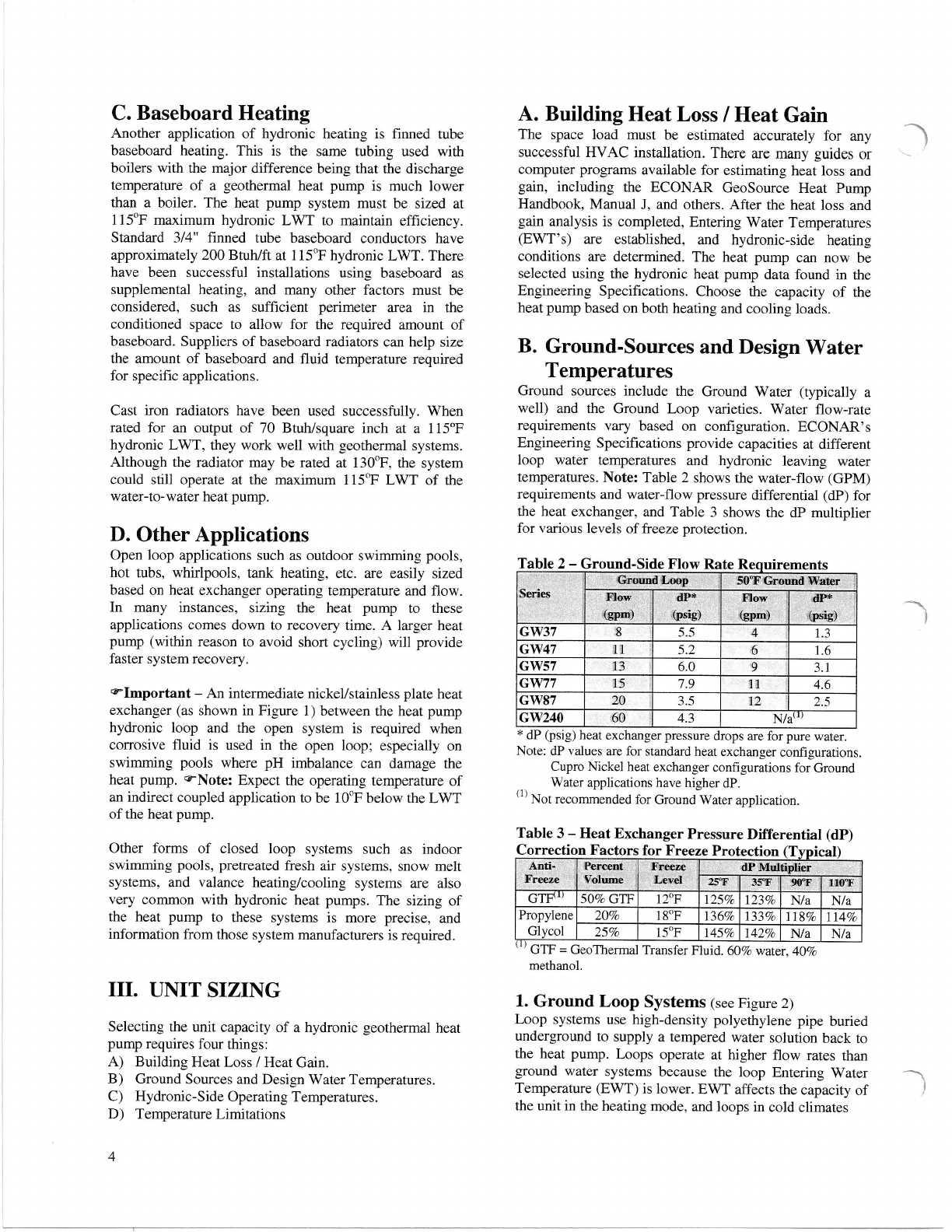
Flow rate requirements for ground loops are higher (see
Table 2) than ground water systems because water
temperatures are generally lower.
VCAUTION - Never operate with flow rates less than
specified. Low flow rates, or no flow, may cause the unit
to shut down on a pressure lockout or may cause a freeze
rupture of the heat exchanger.
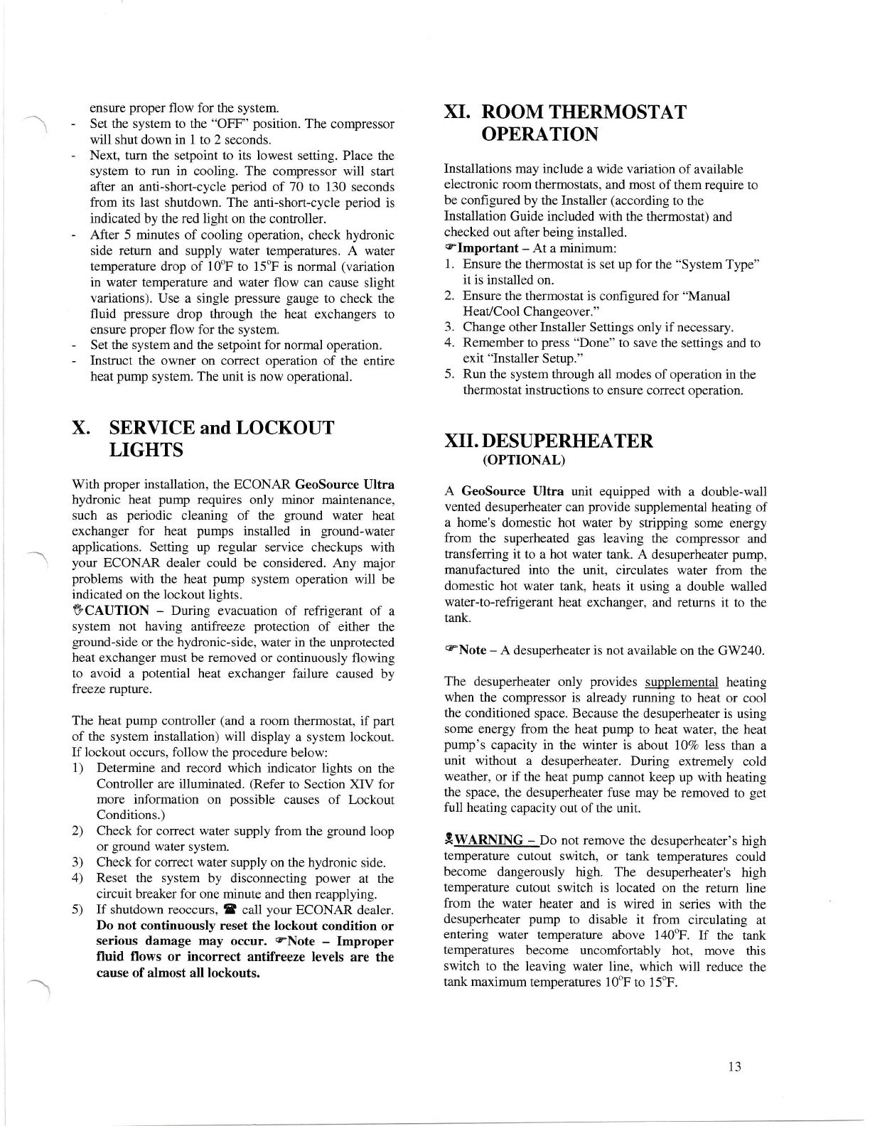
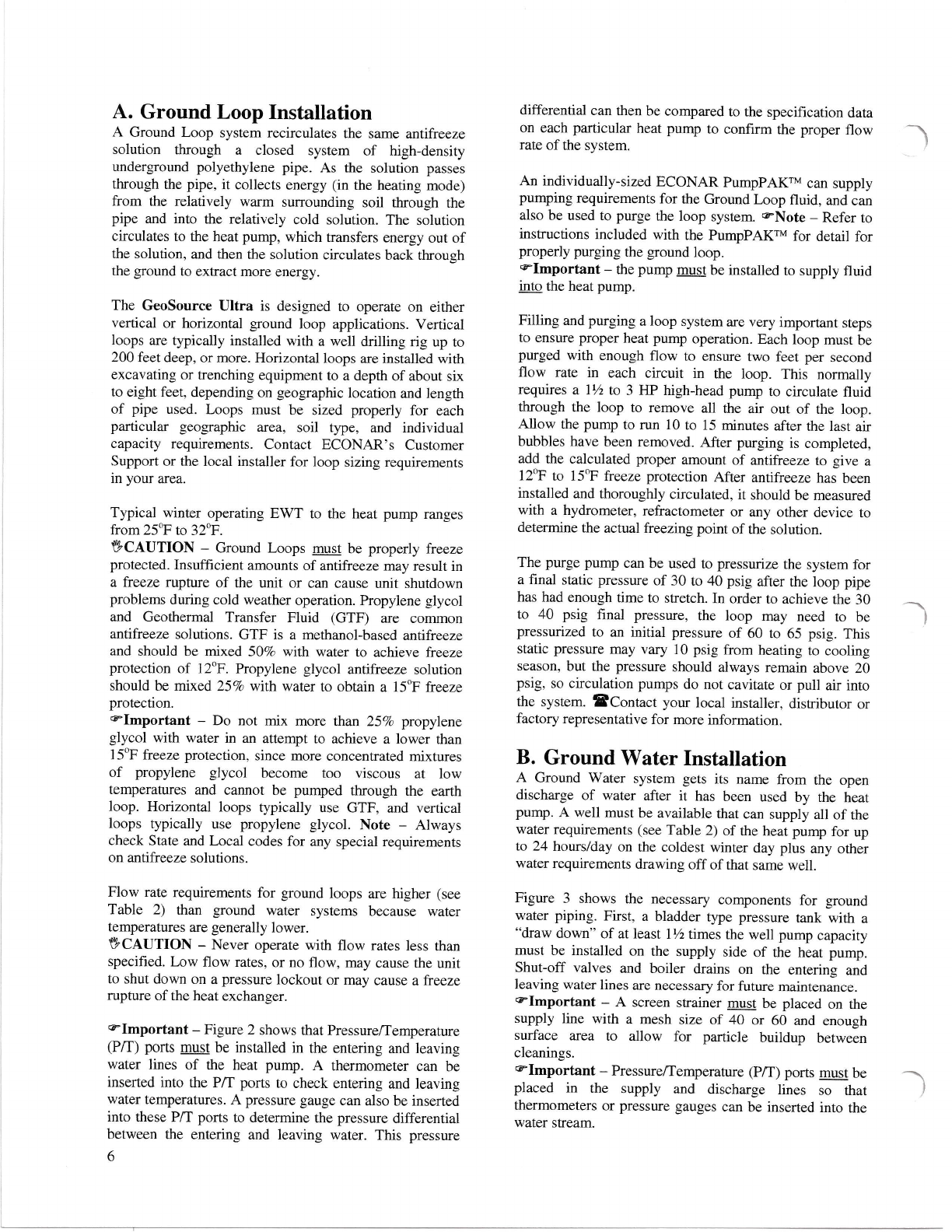
elmportant - Figure 2 shows that Pressure/Temperafure
(P/T) ports must be installed in the entering and leaving
water lines of the heat pump. A thermometer can be
inserted into the P/T ports to check entering and leaving
water temperatures. A pressure gauge can also be inserted
into these P/T ports to determine the pressure differential
between the enterhg and leaving water. This pressure
6
differential can then be compared to the specification data
on each particular heat pump to confirm the proper flow
rate of the system.
An individually-sized ECONAR PumpPAKrM can supply
pumping requirements for the Ground Loop fluid, and can
also be used to purge the loop system. cNote - Refer to
instructions included with the PumpPAKrM for detail for
properly purging the ground loop.
elmportant - the pump must be installed to supply fluid
into the heat pump.
Filling and purging a loop system are very important steps
to ensure proper heat pump operation. Each loop must be
purged with enough flow to ensure two feet per second
flow rate in each circuit in the loop. This normally
requires a lVz to 3 HP high-head pump to circulate fluid
through the loop to remove all the air out of the loop.
Allow the pump to run 10 to 15 minutes after the last air
bubbles have been removed. After purging is completed,
add the calculated proper amount of antifreeze to give a
12oF to 15oF freeze protection After antilreeze has been
installed and thoroughly circulated, it should be measured
with a hydrometer, refractometer or any other device to
determine the actual freezing point of the solution.
The purge pump can be used to pressurize the system for
a final stalic pressure of 30 to 40 psig after the loop pipe
has had enough time to stretch. In order to achieve the 30
to 40 psig final pressure, the loop may need to be
pressurized to an initial pressure of 60 to 65 psig. This
static pressure may vary 10 psig from heating to cooling
season, but the pressure should always remain above 20
psig, so circulation pumps do not cavitate or pull air into
the system. EContact your local installer, distributor or
factory representative for more information.
B. Ground Water Installation
A Ground Water system gets its name from the open
discharge of water after it has been used by the heat
pump. A well must be available that can supply all of rhe
water requirements (see Table 2) of the heat pump for up
to 24 hotsrs/day on the coldest winter day plus any other
water requirements drawing off of that same well.
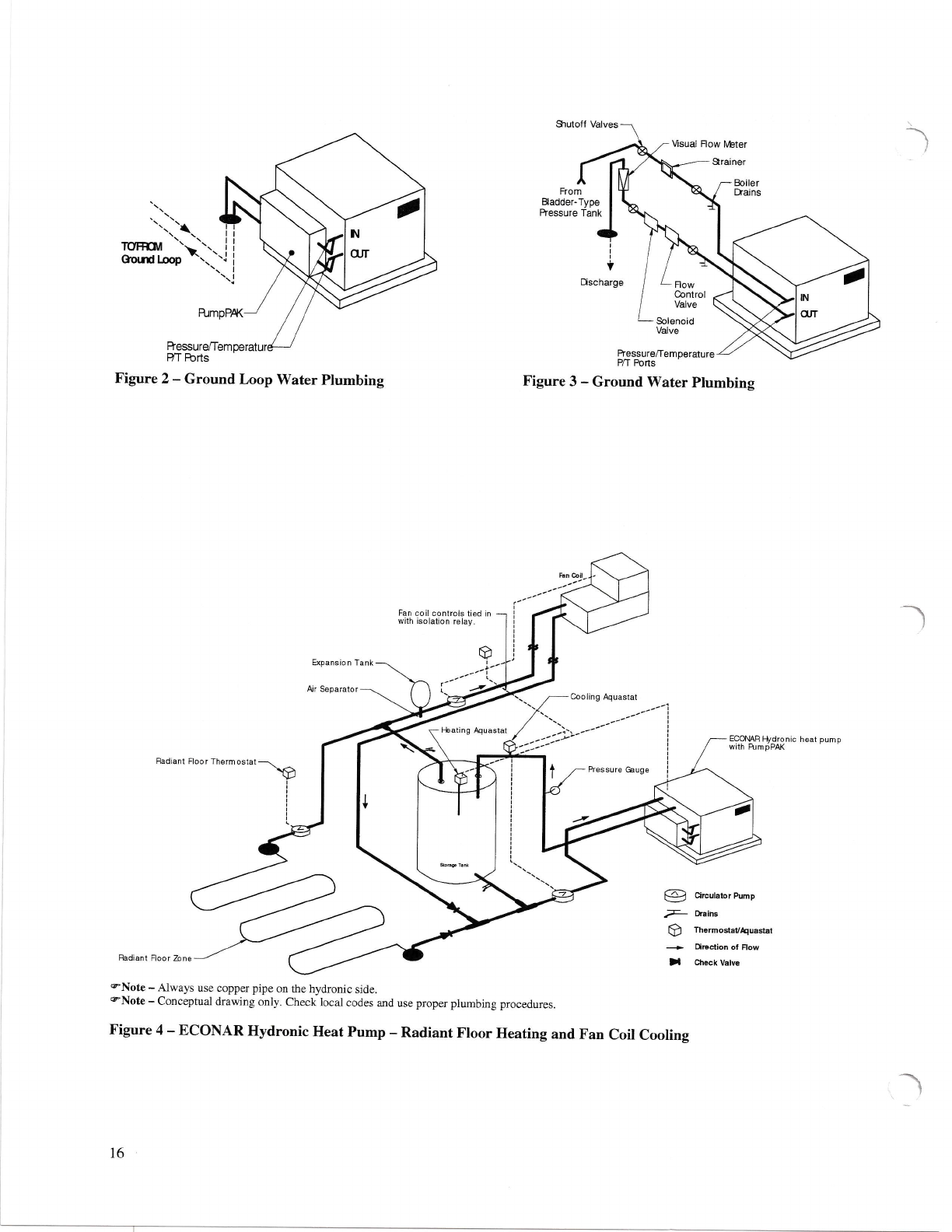
Figure 3 shows the necessary components for ground
water pipiag. First, a bladder tlpe pressure tank with a
"draw down" of at least lVzttmes the well pump capacity
must be installed on the supply side of the heat pump.
Shut-off valves and boiler drains on the entering and
leaving water lines are necessary for future maintenance.
elmportant - A screen strainer must be placed on the
supply line with a mesh size of 40 or 60 and enough
surface area to allow for particle buildup between
cleanings.
elmportant - Pressure/Temperature @/T) ports must be
placed in the supply and discharge lines so that
thermometers or pressure gauges can be inserted into the
water stream.

elmportant - A visual flow meter must be installed to
allow visual inspection of the flow to determine when
maintenance is required. (If you can't read the flow,
cleaning is required. See Water Coil Maintenance for
cleaning instructions.)
A solenoid control valve must be installed on the water
discharge side of the heat pump to regulate the flow
through the unit. Wire the solenoid to the '?lug,
Accessory" connector on the controller. This valve opens
when the unit is running and closes when the unit stops.
Schedule 40 PVC piping, copper tubing, polyethylene or
rubber hose can be used for supply and discharge water
liaes. Make sure line sizes are large enough to supply the
required flow with a reasonable pressure drop (generally
l" diameter minimum).
Water discharge is typically made to a drain field, stream,
pond, surface discharge, tile line, or storm sewer.
elmportant -ensure the discharge line has a pitch of at
least three inches per 12 feet, has a minimum 2 feet of
unobstructed freefall at the end of the line, and has at least
100 feet of grade sloping away from the discharge outlet.
VCAUTION - A drain field requires soil conditions and
adequate sizing to ensure rapid percolation. Consult local
codes and ordinances to assure compliance. DO NOT
discharge water to a septic system.
VCAUTION - Never operate with flow rates less than
specified. L,ow flow rates, or no flow, may cause the unit
to shut down on a pressure lockout or may cause a freeze
rupture of the heat exchanger.
1. Ground Water Freeze Protection
VCAUTION - Only specifically ordered equipment with
a factory-installed 65 psig low-pressure switch can be
used on ground water applications. (The low-pressure
switch on a ground loop system has a 50 psig nominal
cutout pressure.) If the water supply to the heat pump
were intemrpted for any reason, continued operation of
the compressor would cause the water remaining in the
heat exchanger to freeze and rupture the heat exchanger
and may void warranty.
2. Water Coil Maintenance
Water quality is a major consideration for ground water
systems. Problems can occur from scaling, pafiicle
buildup, suspended solids, corrosion, pH levels outside
the 7 -9 range, biological growth, or water hardness of
greater than 100-PPM. If poor water quality is known to
exist in your area, a cupro-nickel water coil may be
required when ordering the system; or installing a ground
loop system may be the best alternative. Water coil
cleaning on ground water systems may be necessary on a
regular basis. Depending on the specific water quality
issue, the water coil can be cleaned by the following
methods (Note - always remember to clean the strainer.):
a. Chlorine Cleaning (Bacterial Growth)
1. Turn off all power to the heat pump during this
procedure.
2. Close the shut-off valves upstream and downsffeam of
the heat exchanger.
3. Connect a submersible circulating pump to the hose
bibs on the entering and leaving water sides of the heat
exchanger.
4. Submerse the pump in a five-gallon pail of water with
enough chlorine bleach to kill the bacteria. Suggested
mixture is 1 part chlorine bleach to 4 parts water.
5. Open the hose bibs to allow circulation of the solution.
6. Stafi the pump and circulate the solution through the
heat exchanger for 15 to 60 minutes. The solution
should change color to indicate the chlorine is killing
and removing the bacteria from the heat exchanger.
7. Flush the used solution by adding a fresh water supply
to the pail. Flush until the leaving water is clear.
8. Repeat this procedure until the solution runs clear
through the chlorine circulation process.
This procedure can be repeated annually, semiarrnually, or
as often as it takes to keep bacteria out of the heat
exchanger, or when bacteria appears in a visual flowmeter
to the point the flow cannot be read.
Another alternative to bacteria problems is to shock the
entire well. Shocking the well may give longer term relief
from bacteria problems than cleaning the heat exchanger,
but will probably need to be repeated, possibly every
three to five years. SContact a well driller in your area
for more information.
b. Muratic Acid Cleaning (Dif{icult Scaling and
Particle Buildup Problems)
1. EWARNING * Consult installer because of the
dangerous nature of acids. Only an experienced and
trained professional should perform this procedure.
(Note - CLR, Iron-Out or other de-scaling products
may be a better alternative before using Muratic Acid.)
2. Turn off all power to the heat pump during this
procedure.
3. Close the shut-off valves upstream and downstream of
the heat exchanger.
4. Connect a submersible circulating pump to the hose
bibs on the entering and leaving water sides of the heat
exchanger. Note - these are corrosive chemicals, so
use a disposable or a suitable pump.
5. Submerse the pump in a five-gallon pail of water with
a small amowt of muratic acid to create a final
concentration of 5Vo mtrattc acid.
9WARN[.{G - Always add acid ro water; never add
water to acid.
6. Open the hose bibs to allow circulation.
7. Start the pump and circulate the solution through the
heat exchanger for about 5 minutes until there are no
longer any air bubbles.
7

8. Stop the pump, and let the solution stand for about 15
minutes.
9. Flush the solution by adding a fresh water supply to
the pail. Flush until the leaving water is clear. Note -
observe local codes for disposal.
VI. HYDRONIC.SIDE SYSTEM
DESIGN
This section deals with some cofilmon practices used
when coupling the ECONAR GeoSource Ultra hydronic
heat pumps to the space conditioning heat exchanger.
There are so many possible applications for hydronic
systems that they cannot all be covered in this text.
Hopefully these ideas can help in many of your system
designs. qNote - Actual systems must be constructed to
all appropriate codes and according to accepted plumbing
practices.
eCaution - Alwa),s use copper pipe on the hydronic side
of the system.
elmportant - Pressure/Temperature port fittings must
be installed in the entering and leaving hydronic lines of
the heat pump.
A. Storage Tanks
elmportant - The heat pump must be coupled to the
space conditioning system through a water storage tank.
e-Important - The guideline for the total fluid storage in
the system is 10 gallons of fluid for each ton of hydronic
heat pump capacity (examp1e, 50 gallons minimum for a
5-ton unit). Size the storage tank for the difference
between the amount of fluid in the smallest hydronic loop
and what the system requires. If in doubt, size the storage
tark for the total capacity of the heat pump. A properly
sized storage tank eliminates many problems with
multiple zone hydronic systems. These problems include
excessive leaving water temperature if a single zone
cannot dissipate heat quickly enough, and hydronic flow
reduction through the heat pump when only one zone is
calling. This may occur because the hydronic circulating
pump is normally sized to provide the heat pump's
required flow with all zones calling. In applications that
use multiple smaller zones, storage tanks absorb the
relatively large amount of energy supplied by the heat
pump in order to provide longer run times and less
compressor cycling for the heat pump. Storage tanks also
serve to dispense energy in small amounts so that the
conditioned zones have time to absorb heat without
requiring high discharge water temperatures. (The only
instance where a storage tanks is not required is when the
heat pump is coupled to a large heat exchanger containing
the recommended amount of fluid capable of absorbing
the entire capacity of the heat pump.)
Insulated water heaters are commonly used for storage
hnks. eNote - Always check local codes to ensure water
heaters can be used as storage tanks. Using the electric
elements in the tank as a secondary heat source to the heat
8
pump is appealing in some applications, but special
Listing Agency Certifications may be required by many
local codes. Specially listed water heaters are available.
While all hot water tanks are insulated on the top and
sides, many do not have insulation on the bottom. An
insulated pad beneath uninsulated tanks will reduce
energy loss to the floor.
elmportant - The hydronic flow into the storage tank
(particularly a water heater) must not be restricted. If the
water heater has an internal diffirser "dip tube,,, cut it off
at approximately 12 inches into the tank.
The tank temperatue can be controlled with a simple
Aquastat or a setpoint controller. The setpoint controller
senses tank water temperature and outside air temperature
to increase the tank temperature as the outside air
becomes colder. This control scheme provides the highest
heating efficiencies by requiring the lowest possible water
temperature to heat the space. Setting the optimal design
temperatures in tlle conffoller is difficult, and the simple
Aquastat does have its advantages. To help in setpoint
control, the following equation can be used:
Reset Ratio = Desiqn Water Temp - Indoor Design Temp
Indoor Design Temp - Outdoor Design Temp
B. Hydronic Side Circulators
Hydronic circulator pumps transfer the energy supplied
by ECONAR's hydronic heat pumps to the water srorage
tank. Select a quiet operating pump with the ability to )
supply the required flow rate at the system pressure drop.
The circulator supplying the heat pump musr be placed in
the water supply line into the unit to provide the best
pump performance. Individual zone circulators must also
be placed in the supply lines of the heat exchangers they
serve. These pumps are often used as the on/off control
mechanism for the zone they supply as shown in Figure 4.
Zone valves are also commonly used for this purpose
using a cofilmon pump as shown in Figure 5.
eNote - Select a cofilmon pump at the total flow of all
the zones and the highest pressure drop of any one
parallel zone. Small Grundfos pumps (230 Vac) should be
used as circulator pumps. These pumps are impedance
protected and do not require additional fusing if powered
directly from the heat pump.
VCAUTION - Never operate with hydronic flow rates
less than specified. Low flow rates, or no flow, may cause
the unit to shut down on a pressure lockout or may cause
afreeze rupture of the heat exchanger.
Circulator pumps must be sized to provide the required
flow to a heat pump heat exchanger at its corresponding
system pressure drop. This system pressure drop can be
calculated from the pressure drop through the piping, plus
the pressure drop of the water storage tank, and plus the
pressure drop through the heat pump heat exchanger.
Table 4 shows the hydronic water-flow requirements and
pressure drop (dP), and Table 3 shows the dp multiplier

for various levels of freeze protection. This table can be
used for sizhg the circulating pump between the hydronic
side of the heat pump and a storage tank.
Table 4 -Tank Circulators
*Size circulators for specific GW240
Note: See Table 3, Heat Exchanger Pressure Differential (dP)
Correction Factors for Freeze Protection.
Table 4 represents the minimum pump size to supply the
heat pump's required hydronic side flow to a storage tank
at the pressure drop of the heat pump and 30 feet of 3/t"
type K copper tubing (or a combination of approximately
20 feet with typical elbows and fittings) (1-114" pipe on
87 series and2" pipeor'240 series).
A common problem with circulator pumps is trapped air
in the system. This air accumulates in the suction port of
the circulator causing cavitation in the pump, which leads
to premature pump failure and noisy operation. The air
can be eliminated by completely purging the system or by
placing an air separator in the plumbing lines. The entire
system must be purged of air during initial installation
and pressurized to a 10-25 psig static pressure to avoid air
entering the system. This static pressure may fluctuate
when going from the heating to cooling modes but should
always remain above zero. If a leak in the system causes
the static pressure to drop, the leak must be repaired to
assure proper system operation.
The hydronic side circulator supplying the heat pump
should be controlled to run only when the compressor
runs. If the pump is allowed to circulate cold water
through the system during off cycles, the refrigerant il the
heat pump will migrate to the hydronic side heat
exchanger. This can cause heat pump starting problems
(especially when this refrigerant migrates into the
condenser).
C. Circulation Fluid
The fluid circulating through the hydronic side of the
geothermal heat pump system is the transfer medium for
the heating and cooling being supplied to the conditioned
space. Selection of this fluid is very important. Water is
the most readily available fluid but has the drawback of
expansion during freezing which can damage the system.
System operation in the cooling mode, extended power
htemrption to a structure, or disabling of an outside zone
(such as a garuge floor) provides the opportunity for
freezing the circulatiag fluid.
VCAUTION - the hydronic side of rhe system must be
freeze protected to reduce the risk of a freeze rupture of
the unit. A propylene glycol based antifreeze (readily
available through HVAC wholesalers) and water solution
is recommended. A non-flammable arttrfreeze solution is
recommended for use on any hydronic system where heat
is being added to the system for structural heating
purposes. Freeze protection for the hydronic side fluid
down to lSoF (207o propylene glycol by volume in water)
is recommended for most indoor applications. Forfy
percent propylene glycol in water (-5oF freeze protection)
is recommended by radiant tube manufactures for snow
melt applications to protect the tubing from expansion in
outdoor applications. Using over 40Vo n hydronic side
applications can cause pumping problems due to high
viscosity.
The water being added to the system should have 100-
PPM grain hardness or less. Ifpoor water conditions exist
on the site, softened water is recommended, or acceptable
water should be brought in. Bacteria or algae grouth in
the water is a possibility at the temperatures produced in
the heating system and can cause buildup on hydronic
side heat exchanger surfaces, reducing the efficiency of
the system or causing the heat pump to run at higher head
pressures and possibly lock out. A gallon of bleach or
boiler system conditioner can reduce the possibility of
growth and can clean up other components in the system.
D. Expansion Tanks
Expansion talks must be used in the hydronic side of the
water-to-water system to absorb the change in pressure of
the closed system due to the change irr temperature when
heat is supplied to the system. Diaphragm-type expansion
tanks should be used. Use EPDM diaphragm tanks
because they are compatible with glycol-based antifreeze
fluids (butyl rubber diaphragms will slowly dissolve with
glycol-based antifreezes).
Expansion tanks from I to l0 gallons are generally used
with heat pump systems in residential and light
commercial applications. Expansion tanks should be
installed in the system near the suction of the circulator
pump to maintain positive pressure at the circulator pump
and reduce the highest working pressure of the system. A
pressure gauge near the inlet ofthe expansion tank gives a
good indication of how the system is operating.
Pressure relief valves are required on hydronic
applications. A 30 psig relief is adequate if the system is
operated at 12 A 15 psig pressure. If a water heater is
used for a storage tank, the 150 psig pressure relief may
be acceptable (check local codes).
E. Application Diagrams
Figures 1 through 5 show the components of a hydronic
heat pump system discussed above used in some cofitmon
applications. These figures by no means represent all the
9
3V 51.7 15-42F (Brute)
47 14.8 26-tt6
97.0 26-116
77 12 14.1 26-i 16 x Two
87 t4 3.6 26-rL6
240 40 2.1 *
Series FIow (gpm) dP
(nsip)
Grundfos
Circulator

possible hydronic heat pump applications, but they do
show some important principals that can be applied to any
system.
VTI. ELECTRICAL SERVICE
e Note - Always refer to the inside of the electrical box
cover for the correct wiring diagram, and always refer
to the nameplate on the exterior of the cabinet for the
correct electrical specifications.
EWARNING - ELECTRICAL SHOCK CAN CAUSE
PERSONAL INJURY OR DEATH. Disconnecr all
power supplies before installing or servicing electrical
devices. Only trained and qualified service personnel
should install, repair or service this equipment.
9wanr,[n[c- THE uNrr MUST BE pRopERLy
GROUNDED!
The main electrical service must be protected by a fuse or
circuit breaker and be capable of providing the amperes
required by the unit at nameplate voltage. A11 wiring must
comply with the national electrical code and/or any local
codes that may apply. Access to the line voltage contactor
is through the knockouts provided on the side of the heat
pump next to the front corner. Route EMT or flexible
conduit with appropriate size and tlpe of wire.
Ensure adequate supply wiring to minimize the level of
dimming lights during compressor startup on single-phase
installations. Some dimming is normal, and a variety of
start-assist accessories are available if dimming is
objectionable. elmportant - some models already have
a factory-installed start assist. Do not add additional start
assists to those units.
9ClUffOn - route field electrical wiring to avoid
contact with electrically live bare metal parts inside the
elecfrical box and to avoid contact with the surface of the
factory-installed start assist (if provided).
VCAUTION - Three-phase units must be wired properly
to ensure proper compressor rotation. Improper rotation
may result in compressor damage. An electronic phase
sequence indicator must be used to check supply-wiring
phases. Also, the "Wild- 1eg of the three-phase power
must be connected to the middle leg on the contactor.
Important - Only the ECONAR PumpPAKrM is certified
to be wired directly to the compressor contactor and can
be grounded in the grounding lug for 208/230Yac. An
alternative loop pump or a pump for a different supply
voltage must be powered from a separate fused power
supply and controlled through an isolation relay that has
its coil wired to the contacror circuit.
An intemal pump relay provides the electrical power
10
through the 3-pole terminal block (BP) for rhe hydronic-
side circulator pump. The use of impedance protected
pumps eliminates the need for additional fusing. Do not
comect more than a 1/3 horsepower pump to the internal
pump relay terminal block. eNote - The GW240 does
not have aa internal pump relay. A pump for the GW240,
or a pump larger than 1/3 horsepower on any other unit,
must be powered from a separate fused power supply and
controlled through an isolation relay that has its 24Vac
coil wired to the Y and X terminals.
VIIII. aAYOLT CONTROL CIRCUIT
Note - Always refer to the inside of the electrical box
cover for the correct wiring diagram.
There are three basic sections of the low voltage circuit;
transformer, remote hydronic confrols, and controller.
A. Transformer
An internal transformer provides 24Yac for all control
features of the heat pump. Even though the transformer is
larger than the industry standard, it is in a warm electrical
box and can be overloaded quickly. Table 5 shows the
transformer usage for the hydronic heat pumps.
Table 5 - Transformer
@Important - If the system's extemal conffols require
more than shown in Table 5, an external transformer and
isolation relays should be used. Table 5 shows that the
heat pump's internal transformer can easily power the 24-
Volt system. In contrast, Figure 4 shows a fan coil system
with its own power supply, which must interface to the
heat pump to put the heat pump into the cooling mode.
This can be accomplished by using the fan coil's
independent power supply to energize the coil of an
isolation relay with contacts located in heat pump's
control circuit.
9WARNING - The GW240 uses a large-capacity 24yac
Control Transformer, and field wiring to remote hydronic
conffols must be suitable for NEC Class 1.
elmportant - Miswiring of 24Yac control voltage on
system controls can result in transformer burnout.
elmportant - Units with a dual voltage ratfurg (example,
208/230) are factory-wired for the higher volrage
7t6 (2)
4N/A
18
lz 2
I Nre 4 (2)
Ll2 2
10 10
33VA
50
72YA
150
)
Component 37-87 240
Contactor
Pump Relav
Reversins Valve 8
Controller 20-1038
Contactor Pilot Relavs
Plug Accessory (PA)
Total
Transformer VA size

(example, 230). ff connected to a power supply having the
lower voltage, change the wiring to the transformer
primary to the correct lead; otherwise premature failure,
or inability to operate the control components may occur.
B. Remote Hydronic Controls
The GW37-87 heat pump series uses a single-compressor,
and the GW240 has a tandem (two compressors
connected together). The GW240 is configured as stage-
controlled with separate Y and Y2 inputs with an
adjustable time delay for the Y2-controlled contactor.
Consult the instructions packaged with the remote
hydronic controls for proper mounting and operation.
Slmportant - If one remote hydronic control operates
multiple heat pumps, the control wiring of the heat pumps
must be isolated with isolation relays to avoid excessive
voltages or overheating and premature failure of the
control components.
Power is supplied to the remote hydronic control from the
R and X terminals on the heat pump terminal strip.
A single-stage hydronic control (heating Aquastat) on a
storage tank or a wall mounted thermostat may be all that
is required for simple heat-only systems. The contact on
the hydronic control closes and provides 24Yac to the Y
terminal. When using a hydronic control, insert the
'*1 temperature sensor approximately 1/3 of the way down
into the storage tank. Set the hydronic control setpoint to
1 10-1 15oF typical, and set the differential to 15oF to avoid
short cycling.
eCAUTION - The setpoint of the hydronic control must
limit the LWT from the heat pump to a maximum of
120oF to avoid premature failure of the compressor.
A cooling hydronic control (Aquastat) can be mounted on
the water supply line, as shown in Figure 4. This control
acts as a low limit, which shuts the heat pump down when
the cooling water reaches the setpoint (e.g. 45"F).
Changeover from heating to cooling can be achieved in
two ways: 1) a manual toggle switch to select the heating
or the cooling hydronic control (Aquastat), or 2) a cooling
thermostat which powers the coil of a sirrgle pole/double
throw relay to select the heating hydronic conffol
(normally closed contact) or the cooling hydronic control
(normally open contact).
eNote - Always wire the system to shut down (Anti-
short-cycle) between a heating and cooling mode
changeover, or nuisance trip-outs could occur from
changing modes "on the fly."
For Zoning applications, any number or types of
thermostats, Aquastats, or switches can be used with an
independent power supply (typically a 24-volt
traasformer) to activate specific zone controls. These zone
controls are normally either a zone pump (Figure 4) or
zone valves (Figure 5). End switches on the zone valves
can be used to control a pump relay when the zone valve
is open. The pump relay then activates a common pump,
which supplies any number of zones. Example: the fan
coil in Figure 4 could be supplied by the same pump as
the radiant floor system if zone valves were used instead
of two pumps.
C. Controller
The controller receives a signal from the thermostat and
initiates the correct sequence of operation for the heat
pump. The confroller performs the following functions:
1) Compressor Anti-Short Cycle
2\ Compressor Control
3) Ground Loop Pump / Ground Water Initiation
4) Compressor Staging
5) Hydronic Circulator Pump Control
6) 4-Way Valve Control
7) Compressor Lockouts
8) System Diagnostics
9) 24Vac Fuse
10) Plug Accessory
11) Alarm Output
1. Compressor Anti-Short Cycle
An anti-short-cycle is a delay period between the time a
compressor shuts down and when it is allowed to come on
again. This protects the compressor and avoids nuisance
lockout conditions for these two conditions;
1. A 70 to 130-second random time-out period occurs
before a re-start after the last shutdown.
2. A 4-minutelZ5-second to 4-minute/45-second random-
start delay occurs immediately after power is applied
to the heat pump. This occurs only after reapplying
power to the unit. To bypass this timeout while
servicing the unit, apply power, disconnect and
reapply power very quickly to shorten the delay.
2. Compressor Control
When 24Vac is applied to the Y terminal on the wiring
terminal block, the controller then decides, based on
lockout and anti-short-cycle periods, when to bring the
compressor on. The M1 output of the controller energizes
the compressor contactor, and the compressor stays on
until ttre 24Yac is removed from the Y terminal.
3. Ground Loop Pump / Ground Water
Initiation
On ground loop systems, a Ml output from the controller
will energize the contactor, starting the compressor and
the ground loop pump. On ground water systems, a M1
output from the controller will energize the ground water
solenoid valve through the'?lug Accessory" connector.
4. Compressor Staging
The GW240 has staged compressors controlled with
separate Y and Y2 inputs. The Ml output of the controller
energizes the flrst compressor contactor and begins the
time-out of the time delay (adjustable 10 to 1000 seconds
and factory set at 10). After the time-out, a Y2 input can
11
l

energize the 2od compressor contactor. eNote - Ensure
there is always a delay time between the operation of the
two compressors to avoid nuisance low-pressure lockouts.
5. Hydronic Circulator Pump Control
The hydronic circulator pump is energized either directly
with the compressor contactor through the 3-pole terminal
block (BP) or through an isolation relay having its 24yac
coil wired to the Y and X terminals.
6. 4-Way Valve Control
When 24Vac is applied to the O terminal on the wiring
block, the controller energizes its O output to provide
24Vac power to the reversing valve (VR), to switch the
refrigerant circuit to the cooling mode.
7. Compressor Lockouts
The controller will lock out the compressor if either of the
following switches open: 1) high-pressure (600 psig), 2)
Iow-pressure switch (50 psig on ground loop or 65 psig on
ground water), or 3) discharge refrigeraat temperature
(275"F). A lockout condition means that the unit has shut
itself down to protect itself, and will not come back on
until power has been disconnected (via the circuit
breaker) to the heat pump for one minute. Problems that
could cause a lockout situation include:
l. Low water flow or extreme water temperatures
2. Internal heat pump operation problems
3. Cold ambient air temperature conditions
8If a lockout condition exists, the heat pump should not
be reset more fhan once; anfl a service technician should
be called immediately.
VCAUTION - Repeated reset may cause severe damage
to the system and may void warranty. The cause of t}re
lockout must be determined and corrected.
8. System Diagnostics
The controller is equipped with diagnostic LED lights that
indicate the system status at any particular time. The
lights indicate the following conditions:
1"24Yolt systempower GREEN
2. Fault or Lockout YELLOW
3. Anti-short-cycle mode RED
If a room thermostat is installed with the heat pump
system and has a lockout indicator, the controller will
send a signal from L on the terminal strip to a LED on the
thermostat to indicate a lockout condition.
9. 24 Vac Fuse
The conffoller has a glass-cartridge fuse located on the
circuit board adjacent to the 24Yac power connector. The
green system power LED will be off if this fuse is open.
A spare fuse is located in the saddle attached to the side of
the 24Yac power connector, and the GW240 also has a
miniature rocker-type circuit breaker located on the
divider-wall in the electrical box. eNote - Ensure the
new fuse fits tightly in the fuse clips after replacement.
12
10. Plug Accessory (PA)
The Plug Accessory output is internally connected to the
Ml output and is energized whenever Ml turns on the
compressor contactor. The maximum rating of this output
is l0VA sealed and 20VA inrush and is typically intended
to power a24Yac ground water solenoid valve.
11. Alarm Output
This output is a 2-position screw terminal connector
identified as "Fault Test" on the controller board and as
DO on the wiring diagram. It is an isolated dry contract
ouQut (0.1 ohm resistance) that closes during a controller
lockout and is intended for use as an input to a dial-out
type of monitoring system. The maximum electrical rating
is 2mA up to 30Vac or 50mA up ro 40Vdc.
IX. STARTUP / CHECKOUT
Before applying power to the heat pump, check the
following items:
- Water supply plumbing to rhe heat pump is completed
and operating. Manually open the water valve on well
systems to check flow. Make sure all valves are open
and air has been purged from a loop system. Never
operate the system without correct water supply flow
on either the ground side or the hvdronic side.
- All high voltage and all low voltage wiring is correct
and checked out, including wire sizes, fuses and
breakers, Set system to the "OFF'position.
- The heat pump is located in a warm area (above 45oF).
(Starting the system with low ambient temperature
conditions is more difficult.) Do not leave the area
until the space is brought up to operating temperatures.
- Hydronic side water temperatures are warrn enough
(50S or above) to start in the heating mode.
Apply power to the unit. A 4 minute 35 second delay on
power up is programmed into the controller before the
compressor will operate. During this time, the pump relay
will energize the hydronic side-circulating pump. Verify
the flow rate and temperature of the hydronic side flow.
The following steps will ensure the system is heating and
cooling properly. After the initial time-out period, the red
indicator light on the conffoller will shut off. The heat
pump is now ready for operation.
- Turn the heating setpoint to its highest temperature
setting, and place the system to run in heating. The
compressor should start I to 2 seconds later. If an
electronic thermostat is used, it *ay cause its own
compressor delay at this time, but the compressor will
come on after the time-out period.
- After 5 minutes of heating operation, check hydronic-
side return and supply water temperatures. A water
temperature rise of 10oF to 15oF is normal (variation in
water temperature and water flow rate can cause slight
variations). Use a single pressure gauge to check the
fluid pressure drop through the heat exchangers to
I
I

ensure proper flow for the system.
Set the system to the "OFF' position. The compressor
will shut down in 1 to 2 seconds.
Next, turn the setpoint to its lowest setting. Place the
system to run in cooling. The compressor will start
afler an anti-short-cycle period of 70 to 130 seconds
from its last shutdown. The anti-short-cycle period is
indicated by the red light on the conftoller.
After 5 minutes of cooling operation, check hydronic
side return and supply water temperatures. A water
temperatue drop of 101F to 15"F is normal (variation
in water temperature and water flow can cause slight
variations). Use a single pressure gauge to check the
fluid pressure drop through the heat exchangers to
ensure proper flow for the system.
Set the system and the setpoint for normal operation.
Instruct the owner on correct operation of the entire
heat pump system. The unit is now operational.
X. SERVICE and LOCKOUT
LIGHTS
With proper installation, the ECONAR GeoSource Ultra
hydronic heat pump requires only minor maintenance,
such as periodic cleaning of the ground water heat
exchanger for heat pumps hstalled in ground-water
applications. Setting up regular service checkups with
your ECONAR dealer could be considered. Any major
problems with the heat pump system operation will be
indicated on the lockout lights.
VCAUTION - During evacuation of refrigerant of a
system not having wrtifreeze protection of either the
ground-side or the hydronic-side, water in the unprotected
heat exchanger must be removed or contiauously flowing
to avoid a potential heat exchanger failure caused by
freeze rupture.
The heat pump controller (and a room thermostat, if part
of the system installation) will display a system lockout.
If lockout occurs, follow the procedure below:
1) Determine and record which indicator lights on the
Controller are illuminated. (Refer to Section XIV for
more information on possible causes of Lockout
Conditions.)
2) Check for correct water supply from the ground loop
or ground water system.
3) Check for correct water supply on the hydronic side.
4) Reset the system by disconnecting power at the
circuit breaker for one minute and then reapplying.
5) If shutdown reoccurs, I call your ECONAR dealer.
Do not continuously reset the lockout condition or
serious damage may occur. eNote - Improper
{luid flows or incorrect antifreeze levels are the
cause of almost all lockouts.
XI. ROOM THERMOSTAT
OPERATION
Installations may include a wide variation of available
electronic room thermostats, and most of them requi-re to
be configured by the Installer (according to the
Installation Guide included with the thermostat) and
checked out after being installed.
elmportant - At a minimum:
1. Ensure the thermostat is set up for the "System Type"
it is installed on.
2. Ensure the thermostat is configured for "Manual
Heat/Cool Changeover."
3. Change other Installer Settings only if necessary.
4. Remember to press "Done" to save the settings and to
exit "Installer Setup."
5. Run the system through all modes of operation in the
thermostat instructions to ensure correct operation.
XIT. DESUPERHEATER
(OPTIONAL)
A GeoSource Ultra unit equipped with a double-wall
vented desuperheater can provide supplemental heating of
a home's domestic hot water by stripping some energy
from the superheated gas leaving the compressor and
fansferring it to a hot water tank. A desuperheater pump,
manufacfured into the unit, circulates water from the
domestic hot water tank, heats it using a double walled
water-to-refrigerant heat exchanger, and returns it to the
tank.
€Note - A desuperheater is not available on the GW240.
The desuperheater only provides supplemental heating
when the compressor is already running to heat or cool
the conditioned space. Because the desuperheater is using
some energy from the heat pump to heat water, the heat
pump's capacity in the winter is about 107o less than a
unit without a desuperheater. During extremely cold
weather, or if the heat pump cannot keep up with heating
the space, the desuperheater fuse may be removed to get
full heating capacity out of the unit.
9W,q.nNnqC - Oo not remove the desuperheater's high
temperature cutout switch, or tank temperatures could
become dangerously high. The desuperheater's high
temperature cutout switch is located on the return line
from the water heater and is wired in series with the
desuperheater pump to disable it from circulating at
entering water temperature above 140"F. If the tank
temperatures become uncomfortably hot, move this
switch to the leaving water line, which will reduce the
tank maximum temporatures 10"F to 15oF.
13

VC.q.UffON - nunning the desuperheater pump without
water flow will damage the pump. A luse is attached to
the fuseholder and must be inserted in the fuseholder
after the desuperheater is operational.
Important - Do not insert the fuse until water flow is
available, or the pump may be damaged. Remove the fuse
to disable the pump if the desuperheater isn't ir operation.
All air must be purged from the desuperheater plumbing
before the pump is engaged.
To purge small amounts of air from the lines, loosen the
desuperheater pump from its housing by turning the brass
collar. Let water drip out of the housing until flow is
established, and re-tighten the brass collar. Using llZ-inch
copper tubing from the tank to the desuperheater inlet is
recommended to keep water velocities high, avoiding air
pockets at the pump inlet. An air vent in the idet line can
also help systems where air is a problem. If one is used
(we recommend a Watts Regulator brand FV-4 or
Spirovent) mount it near the desuperheater inlet roughly
2-ll2 inches above the horizontal pipe. Shutoff valves
allow access to the desuperheater plumbing without
draining the hot water tank. Keep valves open when pump
is running.
Desuperheater maintenance includes periodically openirg
the drain on the hot water tank to remove deposits. If hard
water, scale, or buildup causes regular problems in water
tanks in your area, it may result in a loss of desuperheater
effectiveness. This may require periodic cleaning with
kon Out or similar products.
eCaution - Insulated copper tubing must be used to run
from the water tank to the desuperheater connections on
the side of the unit.
The built-in desuperheater pump can provide the proper
flow to the desuperheater if the iotal equivalent length of
straight pipe and connections is kept to a maximum of 90
feet of ll2-irrch type L copper tubing (or a combination of
approximately 60 feet with typical elbows and fittings).
This tubing can be connected to the water tank in two
ways:
METHOD I
Using a desuperheater tee installed in the drain at the
bottom of the water heater (See Figure 6). This is the
preferred method for ease of installation, comfort and
efficiency. The tee eliminates the need to tap into the
domestic hot water lines and eliminates household water
supply temperature variations that could occur from
connecting to the hot water pipes. Poor water quality may
restrict the effectiveness of the desuperheater tee by
plugging it with scale or buildup from the bottom of the
tank, restricting water flow.
METHOD 2
Taking water from the bottom drain and returning it to
the cold water supply line (See Figure 7). "tbrs method
maiatains the same comfort and efficiency levels but
increases installation time and cost.
elmportant - This method requires a check valve in the
return line to the cold water supply to prevent water from
flowing backwards through the desuperheater when the
tank is frlling. Water passing through the pump
backwards damages the rotor's bearing, which reduces
pump life and causes noise problems in the pump. Note -
A spring-type check valve with a pressure-drop rating of
l/2 psig or less is recommended.
t4
t
-)
I

XIII. ADDITIONAL FIGURE,S, TABLES, AND APPENDICES
3-\ ey
Valve Dveriing
kpansion Tank
mCNARF /dronic
heat pump
with tumpPA(
Fan Qil
@ qr.grt**,ro
$q zorc ranes
;;E- DaiIE
fi TenrosaUlqr"=bt
--> UrcctionofHow
fressure Guge
Fladiant Floor
lnstantaneous booster
to car w6h - 125F
Gr \,1ash Storage
Tank
+
lntermediate hdiant Floor bne
Fbat Achanger
qNote - Always use copper pipe on the hydronic side.
cNote - Conceptual drawing only. Check loca1 codes and use proper plumbing procedures.
qlmportant - Expect a 1OoF rcmperature differentia"l between supply tank and rcceiving tank when transferring heat with an intermediate heat exchanger
Figure 1 - ECONAR Hydronic Heat Pump - Supplying Radiant Floor Heating, Fan Coil Cooling, and Car Wash
Water Heating for a Service Station
hdiart tbat
SoEge Tart(
15

lromu
AotfdLoop
tumpPAK
PT Forts
Figure 2 * Ground Loop Water Plumbing
Expansion Tank
Radiant Floor Therm
$rutoff Valves
Visual Flow [.bter
Srainer
From
BaddetrType
ftessure Tank
Boiler
Dains
Dscharge Flow
Solenoid
Valve
Pressure/Temoerature
P/T Pons
Figure 3 - Ground Water Plumbing
Aquastat
Control
Valve
Fan coil
with isol controls tied in
lation relay
Air
ECOMR Flvdronic heat DUmD
with RrhtiPAK
@ Grcularr eump
.iE- Drains
e ThermostauAquastat
+ Directioh ot Flow
Dl Check Valve
Radianl Floor U ne
eNote - Always use copper pipe on the hydronic side.
eNot" - conceptual drawing only. check local codes and use proper plumbing procedures.
Figure 4 - ECONAR Hydronic Heat Pump - Radiant Floor Heating and Fan Coil Cooling
Fleating Aquastat
Pressure Gauge
t
I6
-)
ctrT

Grile themosta to oper zone vave only. This sends
flow ro the garage fioor only wtEn tfE otfEr zores tre calling.
whicn bu,le6 lhe hed pump againsl bJrsrs oi cold urder.
Bdiart floor themostats ild
porer supply to open zone
vdvs and activate pump.
mOVRll/dronic
with RrmpPA(
t
Floor Am
Fbverse Fbtum
Garage Hoor ane
eNote - Always use coppor pipe on the hydronic side.
qNote - Conceptual drawing only. Check iocal codes and use proper plumbing procedures.
Figure 5 - ECONAR Hydronic Heat Pump - Multizone System
ccr"D
112' ot 314"
6Fper Flpe
12" Oopper Flpe
Esupe&eder Srutofi \Alves
Dain (l-{ng
Dain (-hng
Q q.datotR tp
$q arorar*
- tlaiE
e TErr.stlrq,stat
--{> Uredion ot Bw
ct-D OEck \hlve
W'ot 3l4"
Opper Hpe
Y2" 6pper Bpe
gutoff \al@
FOr
tor I
Ar
SoEge Tar*
Figure 6 - Preferred Desuperheater Installation Figure 7 - Alternate Desuperheater lnstallation
t7
f€at
t

XIV. TROUBLESHOOTII\G GUIDE FOR LOCKOUT COI\DITIONS
If the heat pump goes into lockout on a high or low once this information is known. eNote - A lockout
pressure switch or discharge refrigerant temperature, the condition is a result of the heat pump shutting itself off to
cause of the lockout can be narrowed down by knowing protect itself, never bypass the lockout circuit. Serious
the operating mode and which switch the unit locked out damage can be caused by the system operating without
on. The following table will help track down the problem lockout protection.
AC power applied off off off off otr Blown fuse or power removed.
AC power applied xxASC indicator on for 4' 35" on powd initialization.
AC power applied xPower applied - unjl running or waiting for a call to run.
Run cycle complete xxASC indicator ON for 70 to 130 seconds after compressor shutdown.
Y call switch and Controller.
xFlash -Check electrical connections between
Pressure switch is open.
Heating-duringYcall xxx-Loss/lack of flow through ground-side heat exchanger.
-I-ow fluid temperatue operation in ground-side heat exchanger.
-Freezing fluid in ground-side heat exchanger (lack of antifreeze).
-Dirty (fouled) ground-side heat exchanger (on ground water systems).
-Low ambient temperature at the heat pump.
-Undercharged / overcharged refrigerant circuit.
-Expansion vaive / sensing bulb malfunction.
-Excessive low flqid temperature in the hydronic-side heat exchanger.
during Y call
low fluid side heat
switch and Controller.
x
m
Flash
x
-Loss/lack of flow throush exchanger
-Low fluid temperature in the hydronic loop.
fluid in the hydronic heat exchanger (lack of antifreeze).
valve / sensing bulb malfunction.
Heating or Cooling -
Y call -Check if High Pressure is open.
-Check electrical connections between
l-ow ambient temperatue at the heat pump.
'Undercharged / overcharged refrigerant circuit.
Heating-duringYcall xxx-Loss/lack of flow through hydronic heat exchanger,
-High fluid temperature in the hydronic loop.
-Overcharged refrigerant cfu cuit.
-Expansion valve / sensing bulb malfunction.
Cooling-duringYcall xxX-Loss/lack of flow through the ground-side heat exchanger.
-High fluid temperature in the ground-side heat exchanger.
-Dirty (fouled) ground-side heat exchanger (on ground water systems).
-Overcharged refrigerant circuit.
-Expansion valve / sensing bulb maltrnction.
Heating or Cooling -
before Y call xx-Check electrical connections between DT switch and Controller.
switch is open.
Heating-duringYcall xXx-Significantly 1ow flow through hydronic side and /or ground-side heat exchanger.
-Above maximum hydronic and / or below minimum ground temperatures.
-Signifi cantly undercharged refrigerant circuit.
Cooling-duringYcall xxX-Signifrcantly low flow through hydronic side and / or ground-side heat
-Above maximum ground and / or below minimum hydronic temperatues.
-Signifi cantly underchargedrefrigerant circuil
exchanger
18
CONDITION CSMMENTS
Heating or Cooling -
xx
I
I
This manual suits for next models
6
Table of contents
Other Econar Heat Pump manuals

Econar
Econar GeoSource 2000 GV Series User manual

Econar
Econar GeoSource 2000 GW Series User manual

Econar
Econar GeoSource PumpPAK GPP 1S25-1-A User manual

Econar
Econar GeoSource 2000 User manual

Econar
Econar GeoSource DualTEK GV Series User manual

Econar
Econar GeoSource Vara 2 Plus User manual

Econar
Econar GeoSource Vara GV Series User manual

Econar
Econar GeoSource Invision 3 Q Series User manual

Econar
Econar GeoSurce Vara 2 Plus GV Series Instruction sheet