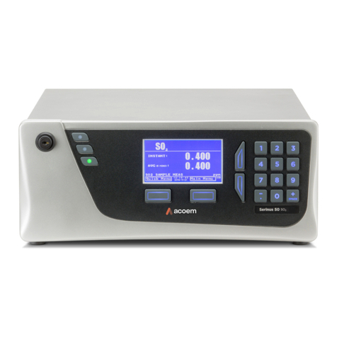
Ecotech Serinus 51 User manual

Serinus 51
SO
2
/H
2
S Analyzer
User Manual
Version: 1.0
July 2011
Tel: (+61) 1300 364 946. Fax: (+61) 1300 668 763.
E-mail: [email protected]
Address: Australia - Head Office
1492 Ferntree Gully rd Knoxfield Victoria, 3180, Australia


Serinus 51 User manual 1.0 Front Matter
i
Manufacturers statement
Thank you for selecting the Ecotech Serinus 51 Sulfur Dioxide Analyzer.
The Serinus series is the next generation of Ecotech designed and manufactured gas
analyzer, the Serinus 51 will perform Sulfur Dioxide measurements over a range of 0-
2ppm with an LDL of 0.5 ppb.
This User Manual provides a complete product description including operating
instructions, calibration, and maintenance requirements for the Serinus 51.
Reference should also be made to the relevant local standards, which should be used
in conjunction with this manual. Some relevant standards are listed in the References
section of this manual.
If, after reading this manual you have any questions or you are still unsure or unclear
on any part of the Serinus 51 then please do not hesitate to contact Ecotech or your
local Ecotech distributor.
Ecotech also welcomes any improvements that you feel would make this a more
useable and helpful product then please send your suggestions to us here at Ecotech.
Please help the environment and recycle the
pages of this manual when finished using it.
Notice
The information contained in this manual is subject to change without notice. Ecotech
reserves the right to make changes to equipment construction, design, specifications
and /or procedures without notice.
Copyright © 2011. All rights reserved. Reproduction of this manual, in any form,
is prohibited without the written consent of Ecotech Pty Ltd.

Front Matter Serinus 51 User manual 1.0
ii
WARNING
Hazardous voltages exist within the analyzer. The analyzer lid should be closed and
quarter turn lid fasteners locked when the analyzer is left unattended or turned on.
Ensure the power cord, plugs and sockets are maintained in a safe working condition
and lid is closed and screw is fastened in place.
Safety requirements
•To reduce the risk of personal injury caused by electrical shock, follow all
safety notices and warnings in this documentation.
•If the equipment is used for purposes not specified by Ecotech, the protection
provided by this equipment may be impaired.
•Replacement of any part should only be carried out by qualified personnel,
using only parts specified by Ecotech as these parts meet stringent Ecotech
quality assurance standards. Always disconnect power source before removing
or replacing any components.

Serinus 51 User manual 1.0 Front Matter
iii
Factory service/warranty
This product has been manufactured in an ISO 9001/ISO 14000 facility with care and
attention to quality.
The product is subject to a 12-month warranty on parts and labor from date of
shipment (the warranty period). The warranty period commences when the product is
shipped from the factory. Lamps, fuses, batteries and consumable items are not
covered by this warranty.
Each analyzer is subjected to a vigorous testing procedure prior to dispatch and will
be accompanied with a parameter list and a multipoint calibration check thereby
enabling the analyzer to be installed and ready for use without any further testing.
To ensure that we process your factory repairs and returned goods efficiently and
expeditiously, we need your help. Before you ship any equipment to our factory,
please call your local Ecotech service response centre (or distributor) to obtain a
return authorization number.
When you contact Ecotech please provide the following information:
1. your name, telephone number and Facsimile number
2. Your company name
3. The model number or a description of each item
4. The serial number of each item, if applicable
5. A description of the problem or the reason you are returning the equipment
(e.g. sales return, warranty return, calibration, etc)
If you are required to return the equipment an accompanying document with:
1. Your name, number and Facsimile number
2. Your company name with return shipment
3. The model number or a description of each item
4. The serial number of each item, if applicable
A description of the problem/reason you are returning the equipment

Front Matter Serinus 51 User manual 1.0
iv
CE Mark Declaration of Conformity
This declaration applies to the Serinus 51 SO
2
analyzers as manufactured by Ecotech Pty. Ltd. of 1492
Ferntree Gully Rd, Knoxfield, VIC, 3180, Australia, and which may be sold in the following
configurations:
To which this declaration relates is in conformity with the following European Union Directives:
Council Directive of 15 December 2004 on the approximation of the laws of Member
States relating to electromagnetic compatibility (2004/108/EC)
The following standard was applied:
EN 61326-1:2006 Electrical Equipment for measurement, control and
laboratory use – EMC Requirements – Part 1: General
requirements.
•Immunity Requirements EN61326-1
IEC-61000-4-2 Electrostatic discharge immunity
IEC-61000-4-3 Radiated RF immunity
IEC-61000-4-4 Electrical fast transient burst immunity
IEC-61000-4-5 Surge immunity
IEC-61000-4-6 Conducted RF Immunity
IEC-61000-4-11 Voltage dips and interruption immunity
•Electromagnetic compatibility EN61326-1
CISPR-11 Radiated RF emission measurements
CISPR-11 Mains Terminal RF emission measurements
IEC-61000-3-3 Mains Terminal voltage fluctuation measurements
IEC-61000-3-2 Power Frequency harmonic measurements
Council Directive of 12 December 2006 on the harmonization of the laws of Member
States relating to electrical equipment designed for use within certain voltage limits
(2006/95/EC)
The following standard was applied:
EN 61010-1:2001 Safety requirements for electrical equipment, for
measurement control and laboratory use – Part 1:
General requirements
•For protection against:
Electric shock or burn
Mechanical HAZARDS
Excessive temperature
Spread of fire from the equipment
Effects of radiation, including laser sources and sonic and ultrasonic
pressure
Serinus 51 User manual 1.0 Front Matter
v
Claims for Damaged Shipments and
Shipping Discrepancies
Damaged shipments
1. Inspect all instruments thoroughly on receipt. Check materials in the
container(s) against the enclosed packing list. If the contents are damaged
and/or the instrument fails to operate properly, notify the carrier and Ecotech
immediately.
2. The following documents are necessary to support claims:
a. Original freight bill and bill lading
b. Original invoice or photocopy of original invoice
c. Copy of packing list
d. Photographs of damaged equipment and container
e. Contact you freight forwarder for insurance claims
You may want to keep a copy of these documents for your records also.
Refer to the instrument name, model number, serial number, sales order
number, and your purchase order number on all claims. Upon receipt of a
claim, we will advice you of the disposition of your equipment for repair or
replacement.
Shipping Discrepancies
Check all containers against the packing list immediately on receipt. If a shortage or
other discrepancy is found, notify the carrier and Ecotech immediately. We will not be
responsible for shortages against the packing list unless they are reported promptly
(within 7 days).

Front Matter Serinus 51 User manual 1.0
vi
Internationally recognized symbols used
on Ecotech Equipment
Electrical fuse IEC 60417-5016
Earth (ground) terminal IEC 60417-5017
Protective conductor terminal IEC 60417-5017
Equipotentiality IEC 60417-5021
Alternating current IEC 60417-5032
Caution, hot surface IEC 60417-5041
Caution, risk of danger. Refer
to accompanying documents
ISO 7000-0434
Caution, risk of electric shock
ISO 3864-5036

Serinus 51 User manual 1.0 Front Matter
vii

Front Matter Serinus 51 User manual 1.0
viii
Manual Revision History
Ecotech Manual ID: MAN 0080
Manual PN: M010040
Current Revision: 1.0
Date released: July 2011
Description: User Manual for the Serinus 51 SO
2
/H
2
S analyzer
This manual is the full user manual for the Serinus 51 SO
2
/H
2
S analyzer. This manual
contains all relevant information on theory, specifications, installation, operation,
maintenance, calibration, communication and troubleshooting. Any information that
cannot be found within this manual can be found by contacting Ecotech at:
Phone: +61 1300 364 946
Fax: +61 1300 668 763
Address: Ecotech Pty Ltd
1492 Ferntree Gully Rd
Knoxfield Victoria
Australia 3180
Website www.ecotech.com
Edition
Date Summary Pages
1.0 July 2011 Initial release all

Serinus 51 User manual 1.0 Front Matter
ix
Table of Contents
1 INTRODUCTION ............................................................................................................. 1
1.1 D
ESCRIPTION
................................................................................................................... 1
1.2 S
PECIFICATIONS
.............................................................................................................. 1
1.2.1 M
EASUREMENT
.............................................................................................................. 1
1.2.2 P
RECISION
/A
CCURACY
.................................................................................................. 1
1.2.3 C
ALIBRATION
................................................................................................................ 1
1.2.4 P
OWER
........................................................................................................................... 2
1.2.5 O
PERATING CONDITIONS
............................................................................................... 2
1.2.6 C
OMMUNICATIONS
........................................................................................................ 2
1.2.7 P
HYSICAL DIMENSIONS
.................................................................................................. 3
1.3 N
OMENCLATURE
............................................................................................................. 3
1.4 B
ACKGROUND
/
T
HEORY
................................................................................................. 4
1.4.1 M
EASUREMENT
T
HEORY
............................................................................................... 4
1.4.2 K
ALMAN FILTER THEORY
.............................................................................................. 5
1.5 I
NSTRUMENT DESCRIPTION
............................................................................................ 5
1.5.1 P
ARTICULATE FILTER
.................................................................................................... 6
1.5.2 H
YDROCARBON
K
ICKER
................................................................................................ 6
1.5.3 Z
ERO
A
IR
S
CRUBBER
..................................................................................................... 6
1.5.4 R
EACTION
C
ELL
............................................................................................................. 7
1.5.5 M
AIN
C
ONTROLLER
PCB .............................................................................................. 7
1.5.6 R
EFERENCE DETECTOR
P
REAMPLIFIER
.......................................................................... 7
1.5.7 PMT
H
IGH
V
OLTAGE
S
UPPLY AND
P
REAMPLIFICATION
............................................... 7
1.5.8 L
AMP
D
RIVER
PCB........................................................................................................ 8
1.5.9 P
RESSURE
PCB .............................................................................................................. 8
1.5.10 P
OWER SUPPLY
............................................................................................................ 8
1.5.11 C
OMMUNICATIONS
...................................................................................................... 9
2 INSTALLATION ............................................................................................................ 10
2.1 I
NITIAL CHECK
.............................................................................................................. 10
2.2 M
OUNTING
/S
ITING
........................................................................................................ 11
2.3 I
NSTRUMENT SETUP
...................................................................................................... 11
2.3.1 P
NEUMATIC CONNECTIONS
.......................................................................................... 11
2.3.2 P
OWER CONNECTIONS
................................................................................................. 12
2.3.3 C
OMMUNICATIONS CONNECTIONS
.............................................................................. 13
2.3.4 A
NALYZER SET UP
....................................................................................................... 13
2.4 U.S.
EPA
R
EFERENCE SET UP
....................................................................................... 14
2.5 T
RANSPORTING
/S
TORAGE
............................................................................................ 14
3 OPERATION .................................................................................................................. 15
3.1 W
ARMUP
........................................................................................................................ 15
3.2 G
ENERAL OPERATIONAL INFORMATION
..................................................................... 15
3.3 M
AIN SCREEN
................................................................................................................ 16
3.4 S
AMPLING
...................................................................................................................... 17
3.5 M
ENUS AND SCREENS
.................................................................................................... 18
3.5.1 Q
UICK
M
ENU
............................................................................................................... 18

Front Matter Serinus 51 User manual 1.0
x
3.5.2 A
NALYZER
S
TATE
........................................................................................................ 20
3.5.3 G
ENERAL
S
ETTINGS
..................................................................................................... 23
3.5.4 M
EASUREMENT SETTINGS
........................................................................................... 23
3.5.5 C
ALIBRATION MENU
.................................................................................................... 24
3.5.6 S
ERVICE
....................................................................................................................... 26
3.5.7 C
OMMUNICATIONS
...................................................................................................... 31
4 CALIBRATION .............................................................................................................. 35
4.1 Z
ERO
C
ALIBRATION
...................................................................................................... 35
4.2 S
PAN
C
ALIBRATION
...................................................................................................... 35
4.3 M
ULTIPOINT
C
ALIBRATION
......................................................................................... 36
4.4 P
RESSURE CALIBRATION
.............................................................................................. 39
4.5 P
RECISION CHECK
......................................................................................................... 40
5 COMMUNICATIONS .................................................................................................... 42
5.1 RS232
C
OMMUNICATION
.............................................................................................. 42
5.2 USB
C
OMMUNICATION
................................................................................................. 42
5.3 TCP/IP
N
ETWORK
C
OMMUNICATION
......................................................................... 42
5.4 D
IGITAL
/A
NALOG COMMUNICATION
.......................................................................... 46
5.5 S
ERINUS DOWNLOADER PROGRAM
.............................................................................. 48
5.5.1 S
ETTINGS
..................................................................................................................... 48
5.5.2 D
ATA
........................................................................................................................... 50
5.5.3 R
EMOTE SCREEN
.......................................................................................................... 51
5.5.4 R
EMOTE TERMINAL
..................................................................................................... 52
6 SERVICE ........................................................................................................................ 53
6.1 P
NEUMATIC DIAGRAM
.................................................................................................. 53
6.2 M
AINTENANCE TOOLS
.................................................................................................. 53
6.3 M
AINTENANCE SCHEDULE
............................................................................................ 54
6.4 M
AINTENANCE PROCEDURES
....................................................................................... 55
6.4.1 P
ARTICULATE FILTER REPLACEMENT
.......................................................................... 55
6.4.2 C
LEAN FAN
F
ILTER
...................................................................................................... 55
6.4.3 DFU
R
EPLACEMENT
.................................................................................................... 56
6.4.4 Q
UICK
L
EAK TEST
........................................................................................................ 56
6.4.5 A
DVANCED LEAK CHECK
............................................................................................. 58
6.4.6 R
EPLACE
Z
ERO AIR SCRUBBER
.................................................................................... 58
6.4.7 R
EPLACE
PMT
DESICCANT PACK
................................................................................ 59
6.4.8 R
EPLACE
DFU
FILTER
................................................................................................. 60
6.4.9 C
HECK
UV
LAMP ALIGNMENT
..................................................................................... 60
6.4.10 P
RESSURE SENSOR CHECK
......................................................................................... 61
6.5 P
ARTS LIST
..................................................................................................................... 63
6.6 U
PDATING FIRMWARE
.................................................................................................. 64
7 TROUBLESHOOTING ................................................................................................. 65
7.1 Z
ERO
F
LOW
................................................................................................................... 66
7.2 E
LECTRONIC
Z
ERO ADJUST
.......................................................................................... 67
7.3 SO
2
REACTION CELL TEMPERATURE FAILURE
............................................................ 67

Serinus 51 User manual 1.0 Front Matter
xi
8 OPTIONAL EXTRAS.................................................................................................... 69
8.1 D
UAL SAMPLE FILTER
................................................................................................... 69
8.2 R
ACK MOUNT KIT
.......................................................................................................... 69
8.3 I
NTERNAL PUMP
............................................................................................................ 71
8.3.1 P
NEUMATIC DIAGRAM
(
INTERNAL PUMP
).................................................................... 71
8.3.2 A
DDITIONAL COMPONENTS
......................................................................................... 71
8.3.3 R
EMOVED COMPONENTS
............................................................................................. 71
8.3.4 M
ENUS
......................................................................................................................... 71
8.3.5 F
LOW
C
ALIBRATION
.................................................................................................... 71
8.3.6 P
RESSURE
C
ALIBRATION
............................................................................................. 71
8.4 H
IGH PRESSURE ZERO
/
SPAN VALVE
............................................................................. 71
8.4.1 S
INGLE PRESSURIZED CALIBRATION OPTION
............................................................... 71
8.4.2 D
UAL PRESSURIZED CALIBRATION OPTION
................................................................. 72
APPENDIX A ADVANCED PROTOCOL PARAMETER LIST ..................................... 75
APPENDIX B – EC9800 PROTOCOL .............................................................................. 82
APPENDIX C – BAVARIAN PROTOCOL ....................................................................... 84

Front Matter Serinus 51 User manual 1.0
xii
List of Figures
Figure 1 Simple pneumatic diagram.......................................................................................... 4
Figure 2 Optical measurement theory ....................................................................................... 5
Figure 3 Major Components ...................................................................................................... 6
Figure 4 Opening the lid .......................................................................................................... 10
Figure 5 Instrument Back panel............................................................................................... 11
Figure 6. Switching battery off ................................................................................................. 14
Figure 7 Serinus front panel .................................................................................................... 15
Figure 8 Excel graph of Multipoint Calibration......................................................................... 38
Figure 9 Pressure Calibration.................................................................................................. 39
Figure 10 Pressure menu ........................................................................................................ 40
Figure 11 Communication ports .............................................................................................. 42
Figure 11 Device Installer pop up window............................................................................... 43
Figure 12 Device Installer XPort-03......................................................................................... 43
Figure 13 Device Installer - Telnet Configuration .................................................................... 44
Figure 14 Serinus 25 pin microprocessor board (with default jumpers highlighted) ............... 46
Figure 15 External 25pin I/O individual pin descriptions ......................................................... 47
Figure 16 Serinus downloader - settings tab ........................................................................... 49
Figure 17 Serinus Downloader – Data tab .............................................................................. 50
Figure 18 Serinus Downloader – Remote Screen tab............................................................. 51
Figure 19 Serinus downloader - Remote Terminal tab............................................................ 52
Figure 17 Pneumatic diagram ................................................................................................. 53
Figure 18 Removing plunger ................................................................................................... 55
Figure 19 Removing fan filter .................................................................................................. 55
Figure 20 Plugged sample and calibration ports ..................................................................... 57
Figure 21 Zero scrubber removal ............................................................................................ 58
Figure 22 Position of desicant packs....................................................................................... 59
Figure 23 Collets of the UV lamp............................................................................................. 61
Figure 24 Dual filter option installed ........................................................................................ 69
Figure 25 Installation of rack mount brackets.......................................................................... 69
Figure 26 Installation of lid to rack mount brackets ................................................................. 70
Figure 27 Rack slide lock ........................................................................................................ 70
Figure 28 Pneumatic diagram with internal pump ................................................................... 71
Figure 29 Single high pressure calibration option ................................................................... 72
Figure 30 Dual high pressure calibration option...................................................................... 73
List of Tables
Table 1 Maintenance Schedule ............................................................................................... 54
Table 2 Parts List..................................................................................................................... 63
Table 3 Troubleshoot list ......................................................................................................... 65
Table 4 Zero flow Troubleshoot............................................................................................... 66
Table 5 Internal pump additional components ........................................................................ 71
Table 6 Internal pump removed components.......................................................................... 71
Table 7 Advanced Protocol Parameter list .............................................................................. 75
List of Equations
Equation 1 Instrument accuracy .............................................................................................. 37

Serinus 51 User manual 1.0
Introduction
1
1
Introduction
1.1 Description
The Serinus 51 SO
2
/H
2
S analyzer uses UV fluorescent radiation technology to detect
Sulfur Dioxide and Hydrogen Sulfide to a sensitivity of 0.5 ppb in the range of 0-2
ppm. The Serinus 51 measures SO
2
/H
2
S with the following instruments/techniques:
•SO
2
scrubber
•Thermal converter
•Hydrocarbon kicker
•UV lamp
•Fluorescence cell
•Optical bandpass filters
•Photomultiplier tube (PMT)
H
2
S is measured by first scrubbing the SO
2
out of the sample with an SO
2
scrubber,
and then converting H
2
S into SO
2
with a thermal converter, The SO
2
concentration
measured is performed directly with a bypass taking the sample around the SO2
scrubber and thermal converter. All measurements are automatically corrected for gas
temperature and pressure changes and referenced to 0°C, 20°C or 25°C at 1
atmosphere. This allows the Serinus 51 to sample in the most useful range of SO
2
and
H
2
S ambient measurement (0-25 ppb SO
2
in air,). This manual will detail the
operation, calibration, preventive maintenance, cautions and health warnings.
1.2 Specifications
1.2.1 Measurement
Range:
•0-2 ppm auto ranging
Lower detectable limit:
•< 0.5 ppb or 0.2% of concentration reading, whichever is greater; with Kalman
filter active.
1.2.2 Precision/Accuracy
Precision:
•0.5 ppb
Linearity:
•±1% of full scale (from best straight-line fit).
Sample flow rate:
•0.725 slpm
1.2.3 Calibration
Zero drift
•Temperature dependant: 0.1 ppb per °C
•24 hours: < 1.0 ppb
•30 days: < 1.0ppb

Introduction Serinus 51 User manual 1.0
2
Span drift
•Temperature dependant: 0.1% per °C
•24 hours: 0.5% of reading
•30 days: 0.5% of reading
1.2.4 Power
Operating voltage:
•99 to 132 VAC, 198 to 264 VAC, 47 to 63 Hz
Power Consumption:
•311VA max.( typical at start up)
•129VA after warm up
Fuse Rating:
•20x5mm, T 250V, 5A (slow blow).
1.2.5 Operating conditions
Ambient Temperature Range:
•5ºC to 40 ºC (41 ºF to 104 ºF)
Sample pressure dependence:
•5% change in pressure produces less than a 1% change in reading
•Maximum Altitude, 3000m above sea level
1.2.6 Communications
Analog Output
•Menu selectable current output of 0-20 mA, 2-20mA or 4-20 mA
or
•Voltage output of 0 to 5 V, with menu selectable zero offset of 0%, 5%, or
10%.
•Range: 0 full scale from 0-0.05 ppm to 0-20 ppm with 0%, 5%, and 10%
offset.
•Resolution: 0.5 ppb or 0.2% of analog output full scale, whichever is greater.
Analog Input
•Three analog voltage inputs (0-5VDC) CAT I rated.
Digital Output
•RS232 port #1: Normal digital communication or termination panel
connection
•RS232 port #2: Multidrop port used for multiple analyzer connections
on a single RS232
•USB port connection on rear panel
•25 pin connector with discrete status and user control
•USB stick memory (front panel) for data logging, event logging and parameter
storage
•8 Digital Outputs, open collector 150mA each.
•8 Digital Inputs, 0-5VDC, CAT I rated.

Serinus 51 User manual 1.0
Introduction
3
1.2.7 Physical dimensions
Case dimensions:
•Length: 620mm with no handle (24.4” inches)
•Width: 440mm (17.3” inches)
•Height: 178mm/4RU (7” inches)
Weight: 18.1kg
1.3 Nomenclature
Span: A gas sample of known composition and concentration used to
calibrate/check the upper range of the instrument (Sulfur Dioxide).
Zero: Zero calibration uses zero air (SO
2
scrubbed ambient air) to
calibrate/check the lower range of the instrument.
Background: External signals that can be confused with that of the
signal being measured.
Zero drift: the change in instrument response to zero pollutant
concentration over 12hr and 24hr periods of continuous unadjusted
operation.
Automatic zero: The automatic zero performs a zero check at a
specified time through a 24 hour cycle which adjusts the lower limit of
the analyzers.
Zero air: Purified air in which the combined effect of the
concentration of impurities is less than 1% of the relevant midrange of
the analyzer instrument. Sufficient purified air can be obtained by
passing dry ambient air through an activated charcoal filter and a
particulate filter.
External span source: Span gas that is delivered via an external
accredited cylinder (e.g. NATA/NIST).
Sample Air: Sample air is defined as the sample before it has entered
the reaction cell, as distinguished from the exhaust air.
Exhaust air: Exhaust air is the sample air after it has passed through
the reaction/measurement/detection cell and is moving towards being
expelled from the analyzer.
ID and OD: Measurements of tubing, ID is the internal diameter of
tubing, OD is the outer diameter.

Introduction Serinus 51 User manual 1.0
4
1.4 Background/ Theory
Sulfur Dioxide
Sulfur Dioxide is the product of the combustion of sulfur compounds and causes
significant environmental pollution. The main source of SO
2
in the environment are
from various industrial processes such as the burning of coal in power stations, the
extraction of metals from ore and combustion of fuel within automobiles.
Sulfur dioxide is a noxious gas that can cause respiratory damage as well as impairing
visibility when in high concentrations. Sulfur Dioxide also has the potential to form
Acid rain (H
2
SO
4
) which causes health, environmental and infrastructural problems to
human society.
Hydrogen Sulfide
Hydrogen sulfide is created through industrial processes and released into the
atmosphere. The main sources of anthropogenic Hydrogen sulfide (H
2
S) emissions
are from petroleum refineries, paper mills, coke ovens (aluminum, steel, graphite,
electrical, and construction industries) and to a smaller extent tannaries.
Hydrogen sulfide is toxic to many different parts of the human body, it effects the
nervous system most acutely and also inhibits respiration. General harmful levels of
Hydrogen sulfide (H
2
S) exposure are 5-10 ppm, levels above this begin with eye
irritation and lead up to death.
1.4.1 Measurement Theory
The measurement of sulfur dioxide is based on classical fluorescence spectroscopy
principles. Sulfur dioxide (SO
2
) exhibits a strong ultraviolet (UV) absorption
spectrum between 200 and 240nm, when SO
2
absorbs UV from this, emission of
photons occurs (300-400nm). The amount of fluorescence emitted is directly
proportional to the SO
2
concentration. The Serinus 51 follows these principles and
measurement techniques:
•Sample air is passed through a hydrocarbon kicker a device which removes
hydrocarbons from sample air
Figure 1 Simple pneumatic diagram
•A zinc discharge lamp and a UV bandpass filter is used to produce radiation at
214nm.

Serinus 51 User manual 1.0
Introduction
5
•The radiation (214nm) is focused into the fluorescence cell where it interacts
with SO
2
molecules and emits photons uniformly in all directions.
•A portion of the fluorescence is collected and filtered.
•Wavelengths at 310-350nm pass through the filter where they reach the
photomultiplier and record a signal.
•A reference detector monitors the emission from the zinc lamp and is used to
correct for fluctuations in lamp intensity.
Figure 2 Optical measurement theory
•Air drawn from the Background Port is scrubbed via charcoal and then passed
through a particulate filter. This air is then available for use by the
Hydrocarbon Kicker and is also used to perform zero background adjustments.
1.4.2
Kalman filter theory
The Serinus analyzer series use the advanced digital Kalman filter. This filter
provides the best possible compromise between response time and noise reduction for
the type of signal and noise present in ambient air analyzers.
The Kalman filter enhances measurements by making the filter time base variable,
depending on the change rate of the measured value. If the signal rate is changing
rapidly, the instrument is allowed to respond quickly. When the signal is steady, a
long integration time is used to reduce noise. The system continuously analyzes the
signal and uses the appropriate filtering time.
1.5 Instrument description
The Sulfur Dioxide analyzer consists of five main assemblies:
•The pneumatics to transfer sample and exhaust gas

Introduction Serinus 51 User manual 1.0
6
•The sensors for the measurement of SO
2
(optical cell) and other relevant
parameters
•The control system which encompasses all circuit boards, is used to control all
sensors and pneumatic components
•The power supply which supplies power for all the instrument processors
•The Communication module to access data
Figure 3 Major Components
1.5.1 Particulate filter
The Particulate filter is a Teflon 5 micron (µm) filter with a diameter
of 47mm. This filter eliminates all particles larger than 5µm and
condensed water vapour that interfere with sample measurement.
1.5.2 Hydrocarbon Kicker
The Hydrocarbon kicker removes interfering hydrocarbons from
sample air. This is achieved by using counter current exchange, where
an air with a lower concentration moves in an opposite direction to air
with a higher concentration. The high concentration of hydrocarbons
diffuse through a selective permeation membrane to the low
concentration air and are removed with exhaust air. Increasing the flow
of the low concentration air also increase the rate of diffusion.
1.5.3 Zero Air Scrubber
A charcoal scrubber is used to produce SO
2
free air which is used in
the hydrocarbon kicker to remove hydrocarbons from sample air.
Table of contents
Other Ecotech Measuring Instrument manuals

Ecotech
Ecotech Serinus 30 User manual

Ecotech
Ecotech Acoem Serinus 10 User manual

Ecotech
Ecotech Serinus 57 User manual

Ecotech
Ecotech A Series User manual

Ecotech
Ecotech Serinus 44 User manual

Ecotech
Ecotech HiVol 3000 User manual

Ecotech
Ecotech Serinus 40 User manual

Ecotech
Ecotech Acoem Serinus 30 User manual
Popular Measuring Instrument manuals by other brands

Emerson
Emerson Micro Motion G-Series installation manual

AEMC instruments
AEMC instruments DIGITAL FLEXPROBE 400D-6 user manual

Eastech Badger
Eastech Badger Vantage 4000 manual

MGP Instruments
MGP Instruments DOSISYS LDM 210 user manual

Interlogix
Interlogix TVN 2264P Guidelines

Siemens
Siemens VDO EDM eco Release II operating instructions