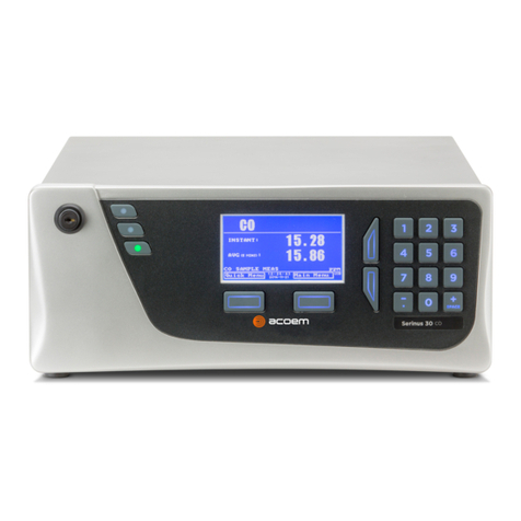
Ecotech Serinus 30 User manual

EP_Ecotech_Serinus30_en.docx
www.umwelt-tuv.de
The department of Environmental Protection of TÜV Rheinland Energie und Umwelt GmbH
is accredited for the following work areas:
- Determination of air quality and emissions of air pollution and odour substances;
- Inspection of correct installation, function and calibration of continuously operating emission measuring instru-
ments, including data evaluation and remote emission monitoring systems;
- Combustion chamber measurements;
- Performance testing of measuring systems for continuous monitoring of emissions and ambient air, and of elec-
tronic data evaluation and remote emission monitoring systems;
- Determination of stack height and air quality projections for hazardous and odour substances;
- Determination of noise and vibration emissions and pollution, determination of sound power levels and execu-
tion of sound measurements at wind energy plants
according to EN ISO/IEC 17025.
The accreditation is valid up to 22-01-2018. DAkkS-register number: D-PL-11120-02-00.
Reproduction of extracts from this test report is subject to written consent.
TÜV Rheinland Energie und Umwelt GmbH
D - 51105 Cologne, Am Grauen Stein, Tel: +49 221 806-2756. Fax: +49 221 806-1349
TÜV RHEINLAND
ENERGIE UND UMWELT GMBH
Report on the performance testing of the Ser-
inus 30 ambient air quality monitoring system
manufactured by Ecotech Pty Ltd measuring CO
TÜV Report: 936/21221977/D_EN
Cologne, 08 October 2013

TÜV Rheinland Energie und Umwelt GmbH
Air Pollution Control
Report on the performance testing of the Serinus 30 ambient air quality moni-
toring system manufactured by Ecotech Pty Ltd measuring CO,
Report no.: 936/21221977/D_EN
Page 3 of 253
EP_Ecotech_Serinus30_en.docx
Report on the performance testing of the Serinus 30 ambient air
quality monitoring system manufactured by Ecotech Pty Ltd
measuring CO
Instrument tested:
Serinus 30
Manufacturer:
Ecotech Pty Ltd
1492 Ferntree Gully Road
Knoxfield VIC Australia 3180
Australia
Test period:
April 2013 to October 2013
Date of report:
08 October 2013
Report number:
936/21221977/D_EN
Editor:
Dipl.-Ing. Guido Baum
Tel.: ++49 221 806-2592
Scope of report: Report:
119
pages
Manual page
119
et seq.
Manual of
134
pages
Total
253
pages in total

TÜV Rheinland Energie und Umwelt GmbH
Air Pollution Control
Report on the performance testing of the Serinus 30 ambient air quality moni-
toring system manufactured by Ecotech Pty Ltd measuring CO,
Report no.: 936/21221977/D_EN
Page 5 of 253
EP_Ecotech_Serinus30_en.docx
Contents
1. SUMMARY AND CERTIFICATION PROPOSAL ...........................................................11
1.1 Summary .......................................................................................................................11
1.2 Certification proposal .....................................................................................................12
1.3 Summary of test results .................................................................................................13
2. TASK DEFINITION ........................................................................................................22
2.1 Nature of the test ...........................................................................................................22
2.2 Objective .......................................................................................................................22
3. DESCRIPTION OF THE ANALYSER TESTED .............................................................23
3.1 Measuring principle .......................................................................................................23
3.2 Analyser scope and set-up ............................................................................................26
4. TEST PROGRAMME ....................................................................................................33
4.1 General .........................................................................................................................33
4.2 Laboratory test ..............................................................................................................33
4.3 Field test ........................................................................................................................34
5. REFERENCE MEASUREMENT METHOD ...................................................................35
6. TEST RESULTS ACCORDING TO VDI 4203 SHEET 3 ................................................36
6.1 4.1.1 Measured value display ....................................................................................36
6.1 4.1.2 Easy maintenance ...........................................................................................37
6.1 4.1.3 Functional check ..............................................................................................38
6.1 4.1.4 Set-up times and warm-up times ......................................................................39
6.1 4.1.5 Instrument design ............................................................................................40
6.1 4.1.6 Unintended adjustment ....................................................................................41
6.1 4.1.7 Data output ......................................................................................................42
6.1 5.1 General ...............................................................................................................43

TÜV Rheinland Energie und Umwelt GmbH
Air Pollution Control
Page 6 of 253
Report on the performance testing of the Serinus 30 ambient air quality
monitoring system manufactured by Ecotech Pty Ltd measuring CO,
Report no.: 936/21221977/D_EN
EP_Ecotech_Serinus30_en.docx
6.1 5.2.1 Certification range ............................................................................................44
6.1 5.2.2 Measuring range ..............................................................................................45
6.1 5.2.3 Negative output signals ....................................................................................46
6.1 5.2.4 Failure in the mains voltage .............................................................................47
6.1 5.2.5 Operating states ...............................................................................................48
6.1 5.2.6 Switch-over ......................................................................................................49
6.1 5.2.7 Maintenance interval ........................................................................................50
6.1 5.2.8 Availability ........................................................................................................51
6.1 5.2.9 Instrument software .........................................................................................52
6.1 5.3.1 General ............................................................................................................53
6.1 5.3.2 Repeatability standard deviation at zero point ..................................................54
6.1 5.3.3 Repeatability standard deviation at span point .................................................55
6.1 5.3.4 Linearity (lack of fit) ..........................................................................................56
6.1 5.3.5 Sensitivity coefficient of sample gas pressure ..................................................57
6.1 5.3.6 Sensitivity coefficient of sample gas temperature .............................................58
6.1 5.3.7 Sensitivity coefficient of surrounding temperature ............................................59
6.1 5.3.8 Sensitivity coefficient of supply voltage ............................................................60
6.1 5.3.9 Cross-sensitivity ...............................................................................................61
6.1 5.3.10 Averaging effect .............................................................................................62
6.1 5.3.11 Standard deviation from paired measurements ..............................................63
6.1 5.3.12 Long-term drift................................................................................................64
6.1 5.3.13 Short-term drift ...............................................................................................65
6.1 5.3.14 Response time ...............................................................................................66
6.1 5.3.15 Difference between sample and calibration port .............................................67
6.1 5.3.16 Converter efficiency .......................................................................................68
6.1 5.3.17 Increase of NO2 concentrations due to residence in the measuring system ....69
6.1 5.3.18 Overall uncertainty .........................................................................................70

TÜV Rheinland Energie und Umwelt GmbH
Air Pollution Control
Report on the performance testing of the Serinus 30 ambient air quality moni-
toring system manufactured by Ecotech Pty Ltd measuring CO,
Report no.: 936/21221977/D_EN
Page 7 of 253
EP_Ecotech_Serinus30_en.docx
7. TEST RESULTS IN ACCORDANCE WITH DIN EN 14626 (2012) ................................71
7.1 8.4.3 Response time .................................................................................................71
7.1 8.4.4 Short-term drift .................................................................................................75
7.1 8.4.5 Repeatability standard deviation ......................................................................79
7.1 8.4.6 Lack of fit of linearity of the calibration function ................................................82
7.1 8.4.7 Sensitivity coefficient to sample gas pressure ..................................................87
7.1 8.4.8 Sensitivity coefficient to sample gas temperature .............................................89
7.1 8.4.9 Sensitivity coefficient to the surrounding temperature ......................................91
7.1 8.4.10 Sensitivity coefficient to electrical voltage .......................................................94
7.1 8.4.11 Interferents .....................................................................................................96
7.1 8.4.12 Averaging test ................................................................................................99
7.1 8.4.13 Difference sample/calibration port ................................................................ 102
7.1 8.5.4 Long-term drift ............................................................................................... 104
7.1 8.5.5 Reproducibility standard deviation for CO under field conditions .................... 107
7.1 8.5.6 Period of unattended operation ...................................................................... 109
7.1 8.5.7 Period of availability of the analyser .............................................................. 110
7.1 8.6 Total uncertainty in accordance with Annex E of DIN EN 14626 (2012) ........... 112
8. RECOMMENDATIONS FOR USE .............................................................................. 117
9. LITERATURE .............................................................................................................. 118
10. ANNEX ........................................................................................................................ 119

TÜV Rheinland Energie und Umwelt GmbH
Air Pollution Control
Page 8 of 253
Report on the performance testing of the Serinus 30 ambient air quality
monitoring system manufactured by Ecotech Pty Ltd measuring CO,
Report no.: 936/21221977/D_EN
EP_Ecotech_Serinus30_en.docx
List of tables
Table 1: Measured range during testing ........................................................................11
Table 2: Technical data for the Serinus 30 measuring system
(manufacturer’s information) ............................................................................32
Table 3: Certification range VDI 4202 Sheet 1 and DIN EN 14626 ................................44
Table 4: Determination of availability .............................................................................51
Table 5: Response times of the two Serinus 30 measuring systems for CO ..................73
Table 6: Individual readings for the response times for the component carbon
monoxide .........................................................................................................74
Table 7: Results for the short-term drift ..........................................................................76
Table 8: Individual test results for the short-term drift (initial values) ..............................77
Table 9: Individual test results for the short-term drift (final values)................................78
Table 10: Repeatability standard deviation at zero and span point ..................................80
Table 11: Individual test results for the repeatability standard deviation ..........................81
Table 12: Residues of the analytical function for CO .......................................................84
Table 13: Individual results of the “lack of fit” test ............................................................86
Table 14: Sensitivity coefficient to sample gas pressure .................................................88
Table 15: Individual test results for the influence of changes in sample gas pressure .....88
Table 16: Sensitivity coefficient to sample gas temperature ............................................90
Table 17: Individual values obtained from the determination of the influence of
sample gas temperature for NO ......................................................................90
Table 18: Sensitivity coefficient to the surrounding temperature at zero point and
at span point, systems 1 and 2 ........................................................................92
Table 19: Individual results of the test of the sensitivity to the surrounding temperature
for CO .............................................................................................................93
Table 20:Sensitivity coefficient to electrical voltage at zero point and at span point .......94
Table 21: Individual results for the tests of the sensitivity coefficient to electrical
voltage ............................................................................................................95
Table 22: Interferents according to DIN EN 14626 ..........................................................97
Table 23: Influence of the interferents (ct = 8.6 µmol/mol) ...............................................97
Table 24: Individual responses to interferents .................................................................98
Table 25: Individual results of the averaging test .......................................................... 101
Table 26: Individual results for the difference between sample and calibration port ...... 103
Table 27: Results for the long term drift at zero for the component CO ......................... 105
Table 28: Results for the long term drift at span point for the component CO................ 105
Table 29: Individual results for the long term drift .......................................................... 106
Table 30: Determination of the reproducibility standard deviation on the basis of all
data collected during the field test ................................................................. 107
Table 31: Availability of the Serinus 30 analyser ........................................................... 111
Table 32: Performance criteria according to DIN EN 14626 .......................................... 113
Table 33: Expanded uncertainty from the results of the laboratory test for system 1 ..... 115
Table 34: Expanded uncertainty from the results of the laboratory and field tests for
system 1........................................................................................................ 115
Table 35: Expanded uncertainty from the results of the laboratory test for system 2 ..... 116
Table 36: Expanded uncertainty from the results of the laboratory and field tests for
system 2........................................................................................................ 116

TÜV Rheinland Energie und Umwelt GmbH
Air Pollution Control
Report on the performance testing of the Serinus 30 ambient air quality moni-
toring system manufactured by Ecotech Pty Ltd measuring CO,
Report no.: 936/21221977/D_EN
Page 9 of 253
EP_Ecotech_Serinus30_en.docx
List of figures
Figure 1: Representation of the Serinus 30 analyser ......................................................23
Figure 2: Illustration of the theoretical measurement method within the cell ....................24
Figure 3: Gas filter correlation wheel ...............................................................................25
Figure 4: Internal components of the Serinus 30 measuring system ...............................26
Figure 5: Internal view of the Serinus 30 measuring system ...........................................27
Figure 6: Pneumatic circuit diagram of the Serinus 30 measuring system .......................31
Figure 7: Rear panel of the Serinus 30 ...........................................................................42
Figure 8: Display of the software version (2.09.0005) on the start screen .......................52
Figure 9: Diagram illustrating the response time .............................................................72
Figure 10: Function established from group averages for system 1, component CO ........84
Figure 11: Function established from group averages for system 2, component CO ........85
Figure 12: Concentration variation for the averaging test (tCO = tzero = 45 s).................... 100
Figure 13: Illustration of the reproducibility standard deviation under field conditions ..... 108

TÜV Rheinland Energie und Umwelt GmbH
Air Pollution Control
Report on the performance testing of the Serinus 30 ambient air quality moni-
toring system manufactured by Ecotech Pty Ltd measuring CO,
Report no.: 936/21221977/D_EN
Page 11 of 253
EP_Ecotech_Serinus30_en.docx
1. Summary and certification proposal
1.1 Summary
Ecotech Pty Ltd has commissioned TÜV Rheinland Energie und Umwelt GmbH to carry out
performance testing of the Serinus 30 measuring system for the component CO.
Testing was performed in compliance with the following standards and guidelines:
• VDI Guideline 4202 Sheet 1: Performance criteria for performance tests of automated
ambient air measuring systems; Point-related measurement methods for gaseous
and particulate air pollutants, September 2010
• VDI Guideline 4203 Sheet 3: Testing of automated measuring systems; Test proce-
dures for point related ambient air measuring systems for gaseous and particulate air
pollutants, September 2010
• DIN EN 14626: Ambient air – Standard method for the measurement of the concen-
tration of carbon monoxide by non-dispersive infrared spectroscopy, December 2012
The Serinus 30 measuring system uses the method of non-dispersive infrared spectroscopy,
which serves as a reference method in the EU, to measure CO. Tests were performed in the
laboratory as well as during a three month field test in Cologne. The measured ranges were
as follows:
Table 1: Measured range during testing
Measured
component
Measured range in [mg/m³] 1) Measured range in [ppm] or [µmol/mol]
CO 0 – 100 0 – 86
1) The data refer to 20°C and 101.3 kPa
Minimum requirements were met during performance testing.
TÜV Rheinland Energie und Umwelt GmbH therefore suggests its type approval for continu-
ous measurement of carbon monoxide concentrations in ambient air.

TÜV Rheinland Energie und Umwelt GmbH
Air Pollution Control
Page 12 of 253
Report on the performance testing of the Serinus 30 ambient air quality
monitoring system manufactured by Ecotech Pty Ltd measuring CO,
Report no.: 936/21221977/D_EN
EP_Ecotech_Serinus30_en.docx
1.2 Certification proposal
Due to the positive results achieved, the following recommendation is put forward for the no-
tification of the AMS as a type-approved measuring system:
AMS designation:
Serinus 30 for CO
Manufacturer:
Ecotech Pty Ltd, Knoxfield, Australia
Field of application:
Continuous measurement of carbon monoxide concentrations in ambient air from stationary
sources.
Measured ranges during performance testing:
Component Certification range Unit
Carbon monoxide 0 - 100 mg/m³
Software version:
Firmware: 2.09.0005
Restrictions:
none
Notes:
1. The measuring system has to be operated in a lockable measuring cabinet or container.
2. The test report on the performance test is available online at www.qal1.de.
Test report:
TÜV Rheinland Energie und Umwelt GmbH, Cologne
Report no.: 936/21221977/D_EN dated 08 October 2013

TÜV Rheinland Energie und Umwelt GmbH
Air Pollution Control
Report on the performance testing of the Serinus 30 ambient air quality moni-
toring system manufactured by Ecotech Pty Ltd measuring CO,
Report no.: 936/21221977/D_EN
Page 13 of 253
EP_Ecotech_Serinus30_en.docx
1.3 Summary of test results
Performance criterion Minimum requirement Test result Com-
pliance Page
4 Requirements on the instrument design
4.1 General requirements
4.1.1 Measured value display Shall be available.
The measuring system is fitted with a
measured value display.
yes 36
4.1.2 Easy maintenance
Necessary maintenance of the
measuring system should be
possible without larger effort, if
possible from outside.
Maintenan
ce can be carried out with
usual tools in a reasonable time and
from the outside.
yes 37
4.1.3 Functional check If the operation or the function-
al check require particular in-
struments, they shall be con-
sidered as part of the measur-
ing system and be applied in
the corresponding sub-tests
and included in the assess-
ment.
The tested instrument does not have
an internal device for functional
checks.
not ap-
plicable
38
4.1.4 Set-up times and warm-
up times
The set-up times and warm-up
times shall be specified in the
instruction manuals.
Set-up times and warm-
up times were
determined.
yes 39
4.1.5 Instrument design
The instruction manual shall
include specifications of the
manufacturer regarding the de-
sign of the system.
The specifications of the manual with
regard to instrument design are com-
plete and correct.
yes 40
4.1.6 Unintended adjustment
It shall be possible to secure
the adjustment of the measur-
ing system against illicit or un-
intended adjustment during
operation.
The
measuring system itself is not
protected against the unintended or
unauthorised adjustment of instru-
ment parameters. It has to be operat-
ed in a lockable measuring container.
no 41
4.1.7 Data output
The output signals shall be
provided digitally and/or as an-
alogue signals.
Measured signals are provided in
analogue (0–20 mA, 2–20 mA, 4–20
mA or 0–
5 V) and digital form (via
TCP/IP, RS 232, USB; Bluetooth).
yes 42

TÜV Rheinland Energie und Umwelt GmbH
Luftreinhaltung
Seite 14 von 253
Report on the performance testing of the Serinus 30 ambient air quality
monitoring system manufactured by Ecotech Pty Ltd measuring CO, Report
no.: 936/21221977/D_EN
EP_Ecotech_Serinus30_en.docx
Performance criterion Minimum requirement Test result Com-
pliance Page
5. Performance characteristics
5.1 General The manufacturer’s specifica-
tions in the instruction manual
shall be by no means better
than the results of the perfor-
mance tests.
No discrepancies between the in-
strument design and the instruction
manuals were observed.
yes 43
5.2 General requirements
5.2.1 Certification range
Shall meet the requirements of
Table 1 of VDI Guideline 4202
Sheet 1.
The measuring system can be as-
sessed in the range o
f the relevant
limit values.
yes 44
5.2.2 Measuring range The upper limit of measure-
ment of the measuring systems
shall be greater or equal to the
upper limit of the certification
range.
By default the measuring range is set
to 0 – 100 mg/m³ for CO. Other
measuring ranges of max. 0 –
200 ppm are possible.
The upper limit of the measuring
range is larger than the respective
upper limit of the certification range.
yes 45
5.2.3 Negative output signals May not be suppressed (life ze-
ro).
The measuring system also displays
negative measured values.
yes 46
5.2.4 Failure in the mains
voltage
In case of malfunction of the
measuring system or failure in
the mains voltage, uncontrolled
emission of operation and cali-
bration gas shall be avoided.
The instrument parameters
shall be
secured by buffering
against loss. When mains volt-
age returns, the instrument
shall automatically reach the
operation mode and start the
measurement.
When mains voltage returns the
measuring system goes back to a
failure-free operational status and au-
tomatically resumes measuring.
yes 47
5.2.5 Operating states The measuring system shall al-
low the control of important op-
erating states by telemetrically
transmitted status signals.
By means of various connectivity op-
tions and the “Serinus Downloader”
software the measuring system can
be monitored and controlled from an
external PC.
yes 48
5.2.6 Switch-over Switch-over between meas-
urement and functional check
and/or calibration shall be pos-
sible telemetrically by computer
control or manual intervention.
In general, all necessary tasks related
to functional checks may be per-
formed directly on-
site or monitored
telemetrically using the remote control
functions.
yes 49
5.2.7 Maintenance interval
Preferably 3 months but at
least 2 weeks.
As determined by the necessary
maintenance tasks the maintenance
interval 4 weeks.
yes 50

TÜV Rheinland Energie und Umwelt GmbH
Luftreinhaltung
Report on the performance testing of the Serinus 30 ambient air quality moni-
toring system manufactured by Ecotech Pty Ltd measuring CO, Report no.:
936/21221977/D_EN
Page 15 of 253
EP_Ecotech_Serinus30_en.docx
Performance criterion Minimum requirement Test result Compli-
ance Page
5.2.8 Availability At least 95 %.
Availability for both systems was
100
% incl. maintenance times during
testing.
yes 51
5.2.9 Instrument software
Shall be displayed during
switch-
on of the measuring
system. The test institute shall
be informed on changes in the
instrument software, which in-
fluence the performance of the
measuring system.
The instrument software version is in-
dicated in the display. Changes to the
software will be communicated to the
test institute.
yes 52
5.3 Requirements on measuring systems for gaseous air pollutants
5.3.1 General
Minimum requirements as per
VDI Guideline 4202 Sheet 1.
The tests were performed on the ba-
sis of the minimum requirements as
stipulated in VDI 4202 Sheet 1 (Sep-
tember 2010) as well as Standard
DIN EN 14626 (2012).
yes 53
5.3.2 Repeatability
standard deviation
at zero point
The repeatability standard de-
viation at zero point shall not
exceed the requirements listed
in Table 1 of VDI Guide-
line
4202 Sheet 1 (September
2010) in the certification range
specified in Table 2
of the
same guideline.
Please refer to section 7.1 8.4.5
Repeatability standard deviation.
yes 54
5.3.3 Repeatability
standard deviation
at span point
The repeatability standard de-
viation at reference point shall
not exceed the requirements
listed in Table 1 of VDI Guide-
line 4202 Sheet 1 (September
2010) in the certification range
according to Table 2
of the
same guideline.
Please refer to section 7.1 8.4.5
Repeatability standard deviation.
yes 55
5.3.4 Linearity (lack of fit) The analytical function describ-
ing the relationship between
the output signal and the value
of the air quality characteristic
shall be linear.
Please refer to section 7.1 8.4.6
Lack of fit of linearity of the cali-
bration function.
yes 56
5.3.5 Sensitivity coeffi-
cient of sample gas
pressure
The sensitivity coefficient of
sample gas pressure at refer-
ence point shall not exceed the
requirements listed in Table 2
of VDI Guideline
4202 Sheet 1
(September 2010).
Please refer to section 7.1 8.4.7
Sensitivity coefficient to sample
gas pressure.
yes 57

TÜV Rheinland Energie und Umwelt GmbH
Luftreinhaltung
Seite 16 von 253
Report on the performance testing of the Serinus 30 ambient air quality
monitoring system manufactured by Ecotech Pty Ltd measuring CO, Report
no.: 936/21221977/D_EN
EP_Ecotech_Serinus30_en.docx
Performance criterion Minimum requirement Test result Com-
pliance Page
5.3.6 Sensitivity coefficient
of sample gas tem-
perature
The sensitivity coefficient of
sample gas temperature at ref-
erence point shall not exceed
the requirements listed in Ta-
ble 2 of VDI Guideline 4202
(September 2010).
Please refer to section 7.1 8.4.8
Sensitivity coefficient to sample
gas temperature.
yes 58
5.3.7 Sensitivity coefficient
of surrounding tem-
perature
The sensitivity coefficient of
surrounding temperature at ze-
ro and reference point shall not
exceed the requirements listed
in Table 2 of VDI Guideline
4202 Sheet 1 (September
2010).
Please refer to section 7.1 8.4.9
Sensitivity coefficient to the sur-
rounding temperature.
yes 59
5.3.8 Sensitivity coefficient
of supply voltage
The sensitivity coefficient of
supply voltage shall not exceed
the requirements listed in Table
2 of VDI Guideline 4202 Sheet
1 (September 2010).
Please refer to section 7.1
8.4.10 Sensitivity coefficient to
electrical voltage.
yes 60
5.3.9 Cross-sensitivity The change in the measured
value caused by interfering
components in the sample gas
shall not exceed the require-
ments listed in Table 2 of VDI
Guideline 4202 Sheet 1 (Sep-
tember 2010) at zero and ref-
erence point.
Please refer to section yes 61

TÜV Rheinland Energie und Umwelt GmbH
Luftreinhaltung
Report on the performance testing of the Serinus 30 ambient air quality moni-
toring system manufactured by Ecotech Pty Ltd measuring CO, Report no.:
936/21221977/D_EN
Page 17 of 253
EP_Ecotech_Serinus30_en.docx
Performance criterion Minimum requirement Test result Com-
pliance Page
5.3.10 Averaging effect
For gaseous components the
measuring system shall allow
the formation of hourly averag-
es.
The averaging effect shall not
exceed the requirements listed
in Table 2 of VDI Guideline
4202 Sheet 1 (September
2010).
Please see section 7.1 8.4.12
Averaging test
yes 62
5.3.11 Standard deviation
from paired meas-
urements
The standard deviation from
paired measurements under
field conditions shall be deter-
mined with two identical meas-
uring systems by paired meas-
urements in the field test. It
shall not exceed the require-
ments listed in Table 2 of VDI
Guideline 4202 Sheet 1 (Sep-
tember 2010).
Please refer to section 7.1 8.5.5
Reproducibility standard deviation
for CO under field conditions.
yes 63
5.3.12 Long-term drift The long-
term drift at zero point
and reference point shall not
exceed the requirements listed
in Table 2 of VDI Guideline
4202 Sheet 1 (September
2010) in the field test.
Please refer to section 7.1 8.5.4
Long-term drift.
yes 64
5.3.13 Short-term drift The short-
term drift at zero
point and reference point shall
not exceed the requirements
listed in Table 2 of VDI Guide-
line 4202 Sheet 1 (September
2010) within 12
h (for benzene
24 h)
in the laboratory test and
within 24 h in the field test.
Please see section 7.1 8.4.4
Short-term drift.
yes 65
5.3.14 Response time
The response time (rise) of the
measuring system shall not ex-
ceed 180 s.
The response time (fall) of the
measuring system shall not ex-
ceed 180 s.
The difference between the re-
sponse time (rise) and re-
sponse time (fall) of the meas-
uring system shall not exceed
10
% of response time (rise) or
10 s, whatever value is larger.
Please refer to section 7.1 8.4.3
Response time.
yes 66

TÜV Rheinland Energie und Umwelt GmbH
Luftreinhaltung
Seite 18 von 253
Report on the performance testing of the Serinus 30 ambient air quality
monitoring system manufactured by Ecotech Pty Ltd measuring CO, Report
no.: 936/21221977/D_EN
EP_Ecotech_Serinus30_en.docx
Performance criterion Minimum requirement Test result Com-
pliance Page
5.3.15 Difference between
sample and calibra-
tion port
The difference between the
measured values obtained by
feeding gas at the sample and
calibration port shall not ex-
ceed the requirements listed in
Table 2 of VDI Guideline 4202
Sheet 1 (September 2010).
Please refer to section 7.1
8.4.13 Difference sam-
ple/calibration port.
yes 67
5.3.16 Converter efficiency
In case of measuring systems
with a converter, the converter
efficiency shall be at least
98 %.
This test item does not apply as the
measuring system does not use a
converter.
Not
appli-
cable
68
5.3.17 Increase of NO2 con-
centrations due to
residence in the
measuring system
In case of NOX measuring sys-
tems the increase of NO2 con-
centration due to residence in
the measuring system shall not
exceed the requirements listed
in Table 2 of VDI Guideline
4202 Sheet 1 (September
2010).
Not applicable as the measuring sys-
tem does not measure NOX.
Not
appli-
cable
69
5.3.18 Overall uncertainty
The expanded uncertainty of
the measuring system shall be
determined. The value deter-
mined shall not exceed the cor-
responding data quality objec-
tives specified in the applicable
EU
Directives on air quality as
listed in Annex A, Table A
1 of
VDI Guideline 4202 Sheet 1
(September 2010).
The determination of uncertainty was
performed in accordance with DIN EN
14626 (2012) and is detailed in sec-
tion 7.1 8.6
Total uncertainty
in accordance with Annex E of DIN
EN 14626 (2012).
yes 70
8.4 Requirements of Standard DIN EN 14626
8.4.3 Response time
Neither the response time
(rise) nor the response time
(fall) shall exceed 180 s.
The
difference between rise and fall
response time shall not exceed
10
% relative difference or
10 s, depending on which val-
ue is larger.
The maximum permissible response
time of 180
s is exceeded at no time.
The maximum response time deter-
mined is 52 s for system 1 and 56 s
for system 2.
yes 71

TÜV Rheinland Energie und Umwelt GmbH
Luftreinhaltung
Report on the performance testing of the Serinus 30 ambient air quality moni-
toring system manufactured by Ecotech Pty Ltd measuring CO, Report no.:
936/21221977/D_EN
Page 19 of 253
EP_Ecotech_Serinus30_en.docx
Performance criterion Minimum requirement Test result Com-
pliance Page
8.4.4 Short-term drift The short-
term drift at zero
shall not exceed 0.10
µmol/mol/12h (i.e. 0.116
mg/m³/12h).
The short-
term drift at span
level shall not exceed 0.6
µmol/mol/12h (i.e. 0.696
mg/m³/12h).
The short-term drift at zero is 0.01
µmol/mol for system 1and -0.08
µmol/mol for system 2.
The short-
term drift at span point is
0.08 µmol/mol for system 1 and 0.18
µmol/mol for system 2.
yes 75
8.4.5 Repeatability
standard deviation
The repeatability standard de-
viation shall neither exceed
0.3 µmol/mol (i.e. 0.348 mg/m³)
at zero nor shall it exceed 0.4
µmol/mol (i.e. 0.464 mg/m³)
at
span point.
The repeatability standard deviation
at zero point is 0.02 µmol/mol for sys-
tem 1 and 0.02 µmol/mol for system
2. The repeatability standard devia-
tion at span point is 0.03 µmol/mol for
system 1 and 0.00 µmol/mol for sys-
tem 2.
yes 79
8.4.6
Lack of fit of linearity
of the calibration
function
The lack of fit of linearity of the
calibration function shall not
exceed 0.5 µmol/mol (i.e. 0.58
mg/m³) at zero and 4 % of the
measured value at concentra-
tions above zero.
For system 1, the deviation from the
regression line is -
0.10 µmol/mol at
zero point and max. 0.86 % of the
target value for concentrations greater
than zero.
For system 2, the deviation
from the regression line is -0.04
µmol/mol at zero point and max. 0.93
% of the target value for concentra-
tions greater than zero.
yes 82
8.4.7 Sensitivity coeffi-
cient to sample gas
pressure
The sensitivity coefficie
nt to
sample gas pressure shall
not
exceed 0.70 µmol/mol/kPa (i.e.
0.81 mg/m³/kPa).
For system 1, the sensitivity coeffi-
cient to sample gas pressure is
0.04 µmol/mol/kPa.
For system 2, the sensitivity coeffi-
cient to sample gas pressure is
0.03 µmol/mol/kPa.
yes 87

TÜV Rheinland Energie und Umwelt GmbH
Luftreinhaltung
Seite 20 von 253
Report on the performance testing of the Serinus 30 ambient air quality
monitoring system manufactured by Ecotech Pty Ltd measuring CO, Report
no.: 936/21221977/D_EN
EP_Ecotech_Serinus30_en.docx
Performance criterion Minimum requirement Test result Com-
pliance Page
8.4.8 Sensitivity coeffi-
cient to sample
gas temperature
The sensitivity coefficient to
sample gas temperature shall
not exceed 0.3 µmol/mol/K (i.e.
0.35 mg/m³/K).
For system 1, the sensitivity coeffi-
cient to sample gas temperature is
0.00 µmol/mol/K).
For system 2, the sensitivity coeffi-
cient to sample gas temperature is
0.00 µmol/mol/K).
yes 89
8.4.9 Sensitivity coeffi-
cient to the sur-
rounding tempera-
ture
The sensitivity coefficient to the
surrounding temperature shall
not exceed 0.3 µmol/mol/K (i.e.
0.35 mg/m³/K).
The sensitivity coefficient to the sur-
rounding temperature does not ex-
ceed the performance criteria of max.
0.3 µmol/mol/K. For both systems, the
highest value bst is used for the pur-
pose of evaluating uncertainty. For
system 1 it is 0.040 µmol/mol/K and
for system 2 it is 0.046 µmol/mol/K.
yes 91
8.4.10 Sensitivity coeffi-
cient to electrical
voltage
The sensitivity coefficient to
electrical voltage shall not ex-
ceed 0.30 µmol/mol/V (i.e. 0.35
mg/m³/V).
The sensitivity coefficient of electrical
voltage bv does not exceed the per-
formance criteria of max. 0.30
µmol/mol/V stipulated in Standard
DIN EN 14626 at any point. For both
systems, the highest value bv is used
for the purpose of evaluating uncer-
tainty. For system 1 it is
0.001
µmol/mol/V and for system 2 it
is 0.001 µmol/mol/V.
yes 94
8.4.11 Interferents
Interferents at zero concentra-
tion and at a concentration ct
(
at the level of the hourly limit
value = 10 mg/m³ for CO
).
Maximum responses for the in-
terferents CO2, NO and NO2
are ≤ 0.5 µmol/mol (i.e. 0.
58
mg/m³) each, and ≤ 1.
0
µmol/mol (i.e. 1.16 mg/m³)
for
H2O.
Cross-
sensitivity at zero point is
0.23
µmol/mol for system 1 and
0.09
µmol/mol for system 2 for the
component H2O; -0.05
µmol/mol for
system 1 and 0.05 µmol/mol for sys-
tem 2 for the component CO2;
0.01
µmol/mol for system 1 and
0.08
µmol/mol for system 2 for the
component NO; 0.01
µmol/mol for
system 1 and 0.00 µmol/mol for sys-
tem 2 for the component N2O.
Cross-sensitivity at the limit value ct is
0.10 µmol/mol for system 1 and -
0.11
µmol/mol for system 2 for the
component H2O; 0.00
µmol/mol for
system 1 and 0.05 µmol/mol for sys-
tem 2 for the component CO2; -
0.11
µmol/mol for system 1 and
0.05 µmol/mol for system 2
for the
component NO; 0.01
µmol/mol for
system 1 and 0.00 µmol/mol for sys-
tem 2 for the component N2O.
yes 96
Table of contents
Languages:
Other Ecotech Measuring Instrument manuals

Ecotech
Ecotech HiVol 3000 User manual

Ecotech
Ecotech Serinus 44 User manual

Ecotech
Ecotech A Series User manual

Ecotech
Ecotech Acoem Serinus 30 User manual

Ecotech
Ecotech Serinus 40 User manual

Ecotech
Ecotech Acoem Serinus 10 User manual

Ecotech
Ecotech Serinus 51 User manual

Ecotech
Ecotech Serinus 57 User manual