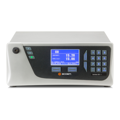
Ecotech A Series User manual

EC9830
A & B Series
Carbon Monoxide
Analyzer
Operation Manual
98307600 Rev. C-1. November 2005
Tel: (61 3) 9894 2399. Fax: (61 3) 9894 2445.
E-mail: ecotech@ecotech.com.au
Spare Parts parts@ecotech.com.au
Address: Australia - Head Office
12 Apollo Court, Blackburn, Melbourne,Victoria, 3130, Australia
Customer Service Web site.www.ecotech.com.au


EC 9830
Quick Start Guide.
Step 1 – Installation:
•Inspect analyzer for damage before turning on. Service Manual:- 1.1.
•Select an appropriate location. Operation Manual:- 2.1.1.
•Connect Gas lines. Operation Manual:- 2.1.2.2.
•Connect Analog Output Cables. Operation Manual:- 2.1.2.1.
•Connect RS232 Cables. Operation Manual:- 4.2.1.
•Check the mains power selection switch (115 or 230 VAC). Operation Manual:- 2.2.
•Connect AC Mains Power. Operation Manual:- 2.2.
Step 2 – Start-up:
•Set Service Switches. Service Manual:- 1.1.2.
•Turn On power. Operation Manual:- 2.2.
•The Display should read “9830 CO Analyzer”.
•Adjust the Display Contrast if required. Operation Manual:- 2.2.1.
•Verify that the software is running by observing the Ecotech Globe rotating in the bottom left
hand corner of the display.
Step 3. – Operation:
•Verify Instrument warm up and operation mode. Service Manual:- 2.2.
•Set the correct time and date. Operation Manual:- 2.3.3.
•If using RS232, configure the Interface menu. Operation Manual:- 2.5.12.
•Check SYSTEM FAULTS menu. All PASS. Operation Manual:- 2.5.21.
•Verify other menu settings. Service Manual:- 4.2.
Step 4. – Calibration:
•Perform a quick (single point) calibration. Operation Manual:- 2.4.
•Setup and Calibrate the Analog Outputs (if applicable). Operation Manual:- 2.6.3.
•If necessary, perform a leak check. Service Manual:- 3.3.10.
•If necessary, perform a flow calibration. Service Manual:- 3.5
•If necessary, perform a Multipoint calibration. Operation Manual:- 3.2.
Step 5. – Data Validation:
•Verify the results from your data acquisition system agree with the readings of the EC9830
CO analyzer.
•Verify that the analyzer responds to automatic calibration sequences.
The analyzer is now operating correctly.


FRONT MATTER
98307600 Rev. C-1
Table of Contents
MANUAL HISTORY.....................................................................................................................................................1
NOTICE ......................................................................................................................................................................2
CE MARK DECLARATION....................................................................................................................................3
INTERNATIONALLY RECOGNIZED SYMBOLS USED ON ECOTECH EQUIPMENT ............................................................4
SAFETY REQUIREMENTS ............................................................................................................................................5
FACTORY SERVICE.....................................................................................................................................................6
CLAIMS FOR DAMAGED SHIPMENTS AND SHIPPING DISCREPANCIES ..........................................................................7
SERVICE AND SPARE PARTS.......................................................................................................................................8
WARNING...............................................................................................................................................................9
1. 0 DESCRIPTION................................................................................................................................................. 1-1
1.1 SPECIFICATIONS ............................................................................................................................................... 1-2
1.1.1 Range ...................................................................................................................................................... 1-2
1.1.2 Noise (RMS) ............................................................................................................................................ 1-2
1.1.3 Lower Detectable Limit........................................................................................................................... 1-2
1.1.4 Zero Drift ................................................................................................................................................ 1-2
1.1.5 Span Drift................................................................................................................................................ 1-2
1.1.6 Lag Time ................................................................................................................................................. 1-3
1.1.7 Rise/Fall Time, 95% of Final Value........................................................................................................ 1-3
1.1.8 Linearity Error........................................................................................................................................ 1-3
1.1.9 Precision ................................................................................................................................................. 1-3
1.1.10 Sample Flow Rate ................................................................................................................................. 1-3
1.1.11 Sample Pressure Dependence............................................................................................................... 1-3
1.1.12 Temperature Range............................................................................................................................... 1-3
1.1.13 Power .................................................................................................................................................... 1-3
1.1.14 Weight ................................................................................................................................................... 1-3
1.1.15 Analog Output....................................................................................................................................... 1-3
1.1.16 Digital Output ....................................................................................................................................... 1-4
1.2 U.S. EPA REFERENCE METHOD ...................................................................................................................... 1-4
2. 0 INSTALLATION AND OPERATION ........................................................................................................... 2-1
2.1 MECHANICAL INSTALLATION ........................................................................................................................... 2-1
2.1.1 Selecting a Location................................................................................................................................ 2-1
2.1.2 Connections............................................................................................................................................. 2-1
2.2 AC POWER CONNECTION................................................................................................................................. 2-7
2.2.1 Display Adjustments................................................................................................................................ 2-8
2.2.2 Warmup................................................................................................................................................... 2-9
2.3 OPERATION .................................................................................................................................................... 2-10
2.3.1 General Operation Information ............................................................................................................ 2-10
2.3.2 Using the Menu and Making Entries .................................................................................................... 2-11
2.3.3 Setting the Date and Time..................................................................................................................... 2-12
2.4 ANALYZER CALIBRATION .............................................................................................................................. 2-13
2.4.1 Precision Checks................................................................................................................................... 2-13
2.4.2 Automatic .............................................................................................................................................. 2-13
2.4.3 Manual .................................................................................................................................................. 2-13
2.4.4 Analyzer Calibration Instructions......................................................................................................... 2-14
2.5 MENUS AND SCREENS.................................................................................................................................... 2-15
2.5.1 Primary Screen ..................................................................................................................................... 2-16
2.5.2 Main Menu ............................................................................................................................................ 2-17
2.5.3 Instrument Menu ................................................................................................................................... 2-17
2.5.4 Measurement Menu............................................................................................................................... 2-18
2.5.5 Calibration Menu.................................................................................................................................. 2-20

EC9830 CO ANALYZER OPERATION MANUAL
98307600 Rev. C-1
2.5.6 Test Menu.............................................................................................................................................. 2-23
2.5.7 Output Test Menu.................................................................................................................................. 2-25
2.5.8 Preprocessor Pots Screen ..................................................................................................................... 2-25
2.5.9 Flow Control Pots Screen (A series only) ............................................................................................. 2-26
2.5.10 Valve Test Menu.................................................................................................................................. 2-27
2.5.11 Diagnostic Menu................................................................................................................................. 2-29
2.5.12 Calculation factors.............................................................................................................................. 2-30
2.5.13 Interface Menu .................................................................................................................................... 2-30
2.5.14 Analog Output Menu........................................................................................................................... 2-31
2.5.15 Data Logging Menu ............................................................................................................................ 2-33
2.5.16 Network Adaptor Menu. ...................................................................................................................... 2-34
2.5.17 Trend Select Menu .............................................................................................................................. 2-34
2.5.18 Event Log Screen ................................................................................................................................ 2-35
2.5.19 Instrument Status Screen..................................................................................................................... 2-35
2.5.20 System Temperatures Screen............................................................................................................... 2-36
2.5.21 System Faults Screen .......................................................................................................................... 2-37
2.6 ANALOG OUTPUT........................................................................................................................................... 2-37
2.6.1 Offset and Live Zero.............................................................................................................................. 2-38
2.6.2 Over Range Adjustment ........................................................................................................................ 2-39
2.6.3 Analog Output Calibration Procedure.................................................................................................. 2-40
2.6.4 Calibration Requirements ..................................................................................................................... 2-41
2.7 PASSWORD PROTECTION................................................................................................................................ 2-41
2.7.1 Rules of Operation ................................................................................................................................ 2-41
2.7.2 Sample Session...................................................................................................................................... 2-42
3. 0 CALIBRATION................................................................................................................................................ 3-1
3.1 OVERVIEW....................................................................................................................................................... 3-1
3.1.1 Analyzer Calibration Instructions........................................................................................................... 3-2
3.2 MULTIPOINT CALIBRATION PROCEDURE.......................................................................................................... 3-3
3.2.1 Procedure Using Cylinder Gas Dilution Method.................................................................................... 3-3
3.2.2 Procedure for 5 Point Multipoint Calibration ........................................................................................ 3-8
3.2.3 Procedure Using Multiple Cylinders .................................................................................................... 3-12
3.3 CALIBRATION REQUIREMENTS WHEN OVER-RANGING IS EMPLOYED ........................................................... 3-12
3.4 AUTOMATIC ZERO/SPAN CHECKS (AZS) ....................................................................................................... 3-13
3.4.1 U.S. EPA Definitions............................................................................................................................. 3-13
3.4.2 AZS Outline........................................................................................................................................... 3-14
3.4.3 AZS Setup.............................................................................................................................................. 3-16
3.4.4 Description of AZS Process .................................................................................................................. 3-17
3.5 CALIBRATION REFERENCES ........................................................................................................................... 3-18
4. 0 DIGITAL COMMUNICATION ..................................................................................................................... 4-1
4.1 DISCRETE CONTROL......................................................................................................................................... 4-1
4.1.1 50-Pin I/O Functional Specification ....................................................................................................... 4-1
4.1.2 50-Pin I/O Inputs .................................................................................................................................... 4-4
4.1.3 50-Pin I/O Outputs.................................................................................................................................. 4-4
4.2 SERIAL CONTROL............................................................................................................................................. 4-5
4.2.1 Serial Connections .................................................................................................................................. 4-5
4.2.2 Cable Connections .................................................................................................................................. 4-6
4.3 SERIAL TERMINAL CONTROL ........................................................................................................................... 4-7
4.4 SERIAL COMMAND CONTROL........................................................................................................................... 4-7
4.4.1 9800 Command Set Format .................................................................................................................... 4-7
4.4.2 Bavarian Network Command Set Format ............................................................................................... 4-8
4.4.3 Protocol Definition and Selection......................................................................................................... 4-10
4.4.4 Establishing Communications............................................................................................................... 4-13
4.4.5 Serial Command Set.............................................................................................................................. 4-15

FRONT MATTER
98307600 Rev. C-1
4.5 USB COMMUNICATION.................................................................................................................................. 4-23
4.5.1 Installing the driver on a PC................................................................................................................. 4-23
4.6 EC9800 COMMUNICATOR SOFTWARE ........................................................................................................... 4-25
4.6.1 Data Acquire Mode............................................................................................................................... 4-25
4.6.2 Remote Terminal Mode ......................................................................................................................... 4-27
4.6.3 Settings.................................................................................................................................................. 4-29
4.6.4 Keyboard shortcuts ............................................................................................................................... 4-30
INDEX ........................................................................................................................................................................30

EC9830 CO ANALYZER OPERATION MANUAL
98307600 Rev. C-1
This page is intentionally left blank.

FRONT MATTER
98307600 Rev. C-1 1
Manual History
This manual is the combination of two previous versions which have now been
merged into one document to cater for the continuing development of the EC9800
series analyzers. The original manuals were:
•ML9830 Operation Manual , PN: 98300068, Rev. R, September 1998.
•ML9830B Operation Manual , PN: 98307005, Rev. K, December 1999.
The scope of this new manual covers the following analyzers:
•EC9830 Carbon Monoxide Analyzer, (A-Series), PN: 98301000-100.
•EC9830B Carbon Monoxide, (B-Series), PN: 98307000-1.
Both of the instruments are Manufactured by Ecotech P/L in Australia and support
the new (SMD) Microprocessor Board (Part number 98000063-4). This manual is
current for firmware version 1.11 and above.
Ecotech Manual ID: #330.
Manual PN: 98307600.
Current Revision: C-1.
Date Released: November 2005.
Description: EC9830 Carbon Monoxide Analyzer, Operation Manual, A & B Series.
Revision History
Rev Date Summary Affected Pages
A Jan 2004 New Release for new Microprocessor Board. A & B
series Combined. Based on original manuals. All
B Feb 2004 Changes to menu options and structure. All
C June 2005 Changed to updated EC manual All
C-1 November
2005 New Calculation factors screen added 2-15, 2-29
NOTE: The photograph on the binder of this manual is of the south coast of Australia during Bushfires in 2003. The
photograph is courtesy of Earth Sciences and Image Analysis Laboratory, NASA Johnson Space Center. Photo
Reference: ISS006-E-19897.

EC9830 CO ANALYZER OPERATION MANUAL
2 98307600 Rev. C-1
Notice
The information contained in this manual is subject to change without notice and
does not represent a commitment on the part of the Ecotech Pty Ltd. Ecotech
reserves the right to make changes in construction, design, specifications, and/or
procedures that may not be reflected in this manual.
Copyright © 2005. All rights reserved. Reproduction in any form is prohibited
without the written consent of Ecotech Pty Ltd.
This manual is furnished on the express condition that the information herein will
not be used for second source procurement, or purposes directly or indirectly
detrimental to the interests of Ecotech.

FRONT MATTER
98307600 Rev. C-1 3
MARK DECLARATION
Declaration of Conformity
Sulfur Dioxide Analyzer
Scope of Declaration
The declaration applies to Sulfur Dioxide Analyzers as manufactured by Ecotech P/L, and which
may be sold in the following configurations:
Part Number Description
98301000-100
98307000-T
98307000-1
98321000-100
98201000-101- 102 -
103
Carbon Monoxide Analyzer
Carbon Monoxide Analyzer Trace
Carbon Monoxide Analyzer, B Series
Carbon Monoxide Analyzer High Level
Carbon Dioxide Analyzer
Ecotech certifies that this product operates in compliance with the following standards:
EN 61326-1 Electrical Equipment for measurement, control and laboratory use – EMC
Requirements Edition 1.1 with amendment 1 plus amendment 2.
Immunity Requirements EN61326-1
IEC-61000-4-11 Voltage Interrupts
IEC-61000-4-11 Voltage Dips
IEC-61000-4-3 Radiated RF electromagnetic field immunity test
IEC-61000-4-4 Electrical fast transient/burst immunity test
IEC-61000-4-5 Surge immunity test
IEC-61000-4-6 Immunity to conducted disturbances, induced by
radio frequency fields
Electromagnetic compatibility EN61326-1
Annex A CISPR 22 and CISPR 16-2
CISPR 16-1 and CISPR 16-2
EN 61010-1 Safety requirements for electrical equipment, control and laboratory use
Section 19 of EN 60204-1
Insulation Resistance Check
Residual Voltage Check
Earth Continuity
The equipment must be operated as per the directions given by Ecotech P/L in this manual.

EC9830 CO ANALYZER OPERATION MANUAL
4 98307600 Rev. C-1
Internationally Recognized Symbols Used on Ecotech Equipment
IEC 60417, No. 5016
Electrical fuse
IEC 60417, No. 5017
Earth (ground) terminal
IEC 60417, No. 5021
Equipotentiality
IEC 60417, No. 5032
Alternating current
IEC 60417, No. 5041
Caution, hot surface
ISO 7000-0434
Caution, refer to
accompanying documents
ISO 3864, No. B.3.6 Caution, risk of electric shock

FRONT MATTER
98307600 Rev. C-1 5
Safety Requirements
To reduce risk of personal injury caused by electrical shock, follow all safety
notices and warnings in this documentation.
This equipment should always be used with a protective earth installed.
The EC9830 is compliant with the requirements of EN61010-1 A2:1995,
Safety Requirements for Equipment for Measurement, Control, and
Laboratory Use.
If the equipment is used for purposes not specified by the manufacturer, the
protection provided by this equipment may be impaired.
Replacement of any part should only be carried out by qualified personnel,
only using parts specified by the manufacturer. Always disconnect power
source before removing or replacing any components.
Surfaces marked with a “Caution, Hot Surface” (see internationally
recognised symbols on page 4) sticker may get hot and deliver burns. Measure
the temperature on the surface before making any contact with it.
Equipment Rating
100-120/220-240V~ ±10%
50/60 Hz
250 VA max
5/3.15A T 250V
All wiring must be in accordance with local norms and be carried out by
experienced personnel.
Environmental Conditions
RELATIVE HUMIDITY 10% to 80%
Temperature 5 to 40 degrees C
Pollution degree 2
Installation category II
Maximum altitude 2000m.
Instruments suitable for use in a sheltered environment only.
Never operate this equipment in the presence of flammable liquids or vapors, as
this could cause a safety hazard.

EC9830 CO ANALYZER OPERATION MANUAL
6 98307600 Rev. C-1
Factory Service
We strive to provide efficient and expedient service when an instrument or component is
returned for repair. Your assistance can help us to better provide the service you need.
To ensure that we process your factory repairs and returned goods efficiently and
expeditiously, we need your help. Before you ship any equipment to our factory, please
call our Service Response Centre at (61 3) 9894 2399. This enables us to complete the
necessary paperwork and process your equipment correctly when it reaches our facility.
When you call, please be prepared to provide the following information:
1. Your name and telephone number
2. Your company name with shipping address
3. The number of items being returned
4. The part number of each item
5. The model number or a description of each item
6. The serial number of each item, if applicable
7. A description of the problem you are experiencing if factory repair is needed, or the
reason you are returning the equipment (eg, sales return, warranty return, etc)
8. The original sales order number or invoice number related to the equipment
9. Whether repair work is under warranty or is to be billed, and a purchase order number
for any work to be billed.
When you call in, our Customer Service Representative will assign a Return Material
Authorization (RMA) number to your shipment and initiate the necessary paperwork to
process your equipment as soon as it reaches us. Please include this RMA number when
you return equipment, preferably both inside and outside the shipping container. This will
ensure that your equipment receives the most prompt attention possible. If the RMA
number is not marked on the outside of the shipping container, the shipment will be
rejected when it reaches our facility, and returned at your expense.
Your assistance in this matter will enable us to serve you better. We appreciate your
cooperation and support of our products and services.

FRONT MATTER
98307600 Rev. C-1 7
Claims for Damaged Shipments and Shipping Discrepancies
Damaged Shipment
1. Inspect all instruments thoroughly on receipt. Check material in the container(s) against the
enclosed packing list. If the contents are damaged and/or the instrument fails to operate
properly, notify the carrier and Ecotech immediately.
2. The following documents are necessary to support claims:
a. Original freight bill and bill of lading
b. Original invoice or photocopy of original invoice
c. Copy of packing list
d. Photographs of damaged equipment and container
You may want to keep a copy of these documents for your records also.
Refer to the instrument name, model number, serial number, sales order number, and your
purchase order number on all claims. Upon receipt of a claim, we will advise you of the
disposition of your equipment for repair or replacement.
Shipping Discrepancies
Check all containers against the packing list immediately on receipt. If a shortage or other
discrepancy is found, notify the carrier and Ecotech immediately. We will not be
responsible for shortages against the packing list unless they are reported promptly.

EC9830 CO ANALYZER OPERATION MANUAL
8 98307600 Rev. C-1
Service and Spare Parts
Address: Ecotech Pty Ltd
12 Apollo crt
Blackburn
Australia. VIC 3130
Phone: +61 3 9894 2399
Fax: +61 3 9894 2445
Email - Service: ecotech@ecotech.com.au
Email - Spare Parts: parts@ecotech.com.au
Web: www.ecotech.com.au
Our Service Response Centre handles product information, application assistance,
factory repair, training, service, maintenance agreements, and technical assistance.
For world wide customer service & spare parts contact ECOTECH:

FRONT MATTER
98307600 Rev. C-1 9
WARNING
Avoid smoking in the vicinity of the analyzer. Due to the complex chemical
makeup of tobacco smoke, smoke drawn into the sample line may result in
incorrect readings. Furthermore, tobacco smoke has been shown to
contaminate converter and scrubber materials critical to the accuracy and
stability of the analyzer.

EC9830 CO ANALYZER OPERATION MANUAL
10 98307600 Rev. C-1
This page is intentionally left blank.

CHAPTER 1, DESCRIPTION
98307600 Rev. C-1 1-1
1.0 Description
The EC9830 carbon monoxide (CO) analyzer is a nondispersive infrared
photometer that accurately and reliably measures low concentrations of CO, using
gas filter correlation and state-of-the-art optical and electronic technology.
The EC9830 analyzer generates infrared radiation (IR) that is absorbed by the CO
within the 5-meter folded pathlength. The gas filter correlation wheel facilitates
rejection of interferents and the narrow band-pass filter ensures measuring only
the CO-sensitive IR wavelengths. The CO content of the sample is continuously
measured from a user-supplied air stream of which the instrument extracts 1 slpm
(standard litre per minute) of sample.
The EC9830 has a built-in catalytic zero air scrubber which provides CO-free air
to the analyzer. The microprocessor automatically resets the zero reading after the
analyzer has sampled air through the converter.
In addition to temperature and pressure compensation, the EC9830 analyzer can
readjust its span ratio based on a known concentration of gas used to span the
analyzer. This feature is not automatically implemented and must be selected by
the operator.
Analog and digital outputs are available for data monitoring. The operator can
select analog output as either current or voltage output. Current ranges are 0-20,
2-20, and 4-20 mA. Voltage outputs include 0-10, 0-5, 0-1, and 0-0.1 volts
(50-pin I/O board optional in EC9830 B series)
Data collection and recording is available to either a data acquisition system (such
as a datalogger) or strip-chart recorder. A convenient DB50 connector is also
included for digital input control and digital output status. The EC9830 also
features internal data storage capabilities.
The instrument also includes an over-range feature that, when enabled,
automatically switches to a preselected higher range if the reading exceeds 90% of
the nominal range. When the reading returns to 80% of the nominal range, the
analyzer automatically returns to that range.
The EC9830 carbon monoxide analyzer is designated as a reference method by the
U.S. EPA. The operational parameters that apply when using the instrument as a
designated reference method are included in section 1.2 below.

EC9830 CO ANALYZER OPERATION MANUAL
1-2 98307600 Rev. C-1
1.1 Specifications
Note
All specifications are referenced to STP (standard
temperature and pressure).
1.1.1 Range
Display: Autoranging 0 to 200 ppm. Resolution = 1 ppt (selectable units and
decimal places).
Analog output: 0-full scale from 0-1 ppm to 0-200 ppm with 0%, 5%, 10%
offset.
Autoranging between 2 user-specified full scale values.
U.S. EPA designated range: Any full scale range between 0-5.0 ppm and
0-100 ppm.
1.1.2 Noise (RMS)
Measurement process: 0.025 ppm or 0.1% of concentration reading,
whichever is greater, with Kalman filter active.
Analog output: 0.025 ppm or 0.1% of analog output full scale, whichever is
greater.
1.1.3 Lower Detectable Limit
Measurement process: Less than 0.05 ppm or 0.2% of concentration reading,
whichever is greater, with Kalman filter active.
Analog output: 0.05 ppm or 0.2% of analog output full scale, whichever is
greater.
1.1.4 Zero Drift
Temperature dependent, 0.01 ppm per °C.
Time dependent, at fixed temperature:
24 hours: Less than 0.1 ppm
30 days: Less than 0.1 ppm
1.1.5 Span Drift
Temperature dependent, 0.05% per °C.
Time dependent, at fixed temperature:
24 hours: 0.5% of reading.
30 days: 0.5% of reading.
This manual suits for next models
3
Table of contents
Other Ecotech Measuring Instrument manuals

Ecotech
Ecotech Acoem Serinus 30 User manual

Ecotech
Ecotech Serinus 40 User manual

Ecotech
Ecotech Acoem Serinus 10 User manual

Ecotech
Ecotech Serinus 44 User manual

Ecotech
Ecotech Serinus 57 User manual

Ecotech
Ecotech Serinus 51 User manual

Ecotech
Ecotech HiVol 3000 User manual

Ecotech
Ecotech Serinus 30 User manual