ECOTEST BDBG-09S User manual

BDBG-09S
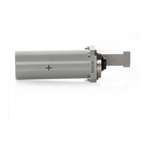
DETECTING UNIT OF GAMMA RADIATION
Operating manual
BICT.418266.032-02 НЕ


2
CONTENTS
1 DESCRIPTION AND OPERATION ...............................................................................................3
2 PROPER USE...................................................................................................................................8
3 MAINTENANCE ...........................................................................................................................11
4 REPAIR ..........................................................................................................................................17
5 STORAGE AND PUTTING IN PROLONGED STORAGE.........................................................17
6 SHIPPING.......................................................................................................................................17
7 DISPOSAL......................................................................................................................................17
APPENDIX А ....................................................................................................................................18
APPENDIX B ....................................................................................................................................26
APPENDIX C ....................................................................................................................................44
APPENDIX D....................................................................................................................................45

3
This operating manual (the OM) is intended to inform the user about principles of operation,
rules of application, maintenance, storage and shipping of the BDBG-09S detecting unit of gamma
radiation.
The OM contains the following abbreviations:
DER - ambient dose equivalent rate
)10(
*
H
of gamma radiation;
PC - personal computer;
GMC - Geiger-Muller counter;
SDUGR - scintillation detecting unit of gamma radiation.
1 DESCRIPTION AND OPERATION
1.1 Purpose of use of the BDBG-09S detecting unit
The BDBG-09S detecting unit of gamma radiation (hereinafter called the detecting unit) is
designed to measure ambient dose equivalent rate
)10(
*
H
of gamma radiation (hereinafter DER).
The BDBG-09 S detecting unit can be used within computer-aided systems for
radiation monitoring instead of the BDBG-09 detecting unit in terms of gamma radiation
DER and temperature measurements without changing the software.
1.2 Technical specifications
1.2.1 Key specifications are presented in the Table 1.1.
Table 1.1 –Key specifications of the detecting unit
Name
Unit of
measurement
Standardized value
according to the
specifications
1 Measurement range of gamma radiation
DER with the SDUGR
μSv/h
0.01 –50
2 Measurement range of gamma radiation
DER with the GMC
μSv/h
50 –106
3 Main relative permissible error limit of
gamma radiation DER measurement at 137Cs
calibration with confidence probability of
0.95
%
15+1/
)10(
*
H
, where
)10(
*
H
is a numeric
value of gamma radiation
DER in μSv/h
4 Energy range of registered gamma radiation
MeV
0.05 –3.00
5 Energy dependence of the detecting unit’s
measurement results during gamma radiation
DER measurement in the energy range of
0.05 - 1.25 MeV
%
25
6 Anisotropy of the detecting unit at gamma
quanta incidence at angles from +60оto - 60о
horizontally and vertically relative to the main
measurement direction, marked by a
“+” symbol , does not exceed:
- for 137Cs and 60Со isotopes
- for 241Am isotope
%
25
60

4
Table 1.1 (continued)
Name
Unit of
measurement
Standardized
value according
to the
specifications
7 Operating supply voltage range of the detecting
unit from external regulated power supply
V
7 - 32
8 Consumption current of the detecting unit for
overall range of measured gamma radiation DER, not
more than
mA
30
9 Setup time of operating mode and measurement
time of the detecting unit, not more than
min
3
10 Unstable readings of the detecting unit for a
24-hour continuous operation, not more than
%
5
11 Complementary permissible error limit of
measurement caused by ambient temperature change
from - 40oC to +50 oC
%
5
per each 10 оС
deviation from
(20 ±5)0С
12 Interface
-
RS-485
13 Dimensions of the detecting unit without fastening
elements, not more than
mm
60х60х170
14 Weight of the detecting unit without fastening
elements, not more than
kg
0.5
1.2.2 Use environment
1.2.2.1 Concerning the resistance to climatic and other environmental factors, the detecting
unit meets the requirements outlined below.
1.2.2.2 The detecting unit is resistant to the influence of the following climatic factors:
- air temperature from –20 оСto 40 оС;
- relative humidity up to 100 % at 40 оСtemperature and lower temperatures with humidity
condensation;
- atmospheric pressure form 84 kPa to 106.7 kPa.
No requirements to other climatic factors.
1.2.2.3 The detecting unit is resistant to sinusoidal vibrations.
1.2.2.4 The detecting unit is tolerant to shocks with the following parameters:
- shock pulse duration –from 5 ms to 10 ms;
- number of shocks –1000±10;
- maximum shock acceleration –100 m/s2.
1.2.2.5 The detecting unit in a shipping container is resistant to the influence of:
- ambient air temperature from - 40 оСto 60 оС;
- relative humidity up to (95 3) % at 35 оСtemperature;
- shocks with acceleration of 98 m/s2, shock pulse duration of 16 ms, and number of shocks –
1000±10.
1.2.2.6 The detecting unit withstands constant or alternating (50 Hz1 Hz) magnetic fields
of 400 A/m voltage.
1.2.2.7 The detecting unit is immune to gamma radiation of exposure dose rate equal to
equivalent dose rate up to 100 Sv/hour during 5 min.

5
1.2.2.8 The detecting unit supports the operability control of the built-in detectors with
formation of check information.
1.1.2.9 Regarding the interference immunity, the detecting unit is referred to as the automation
equipment (AE) that operates in electromagnetic environment of medium hardness.
1.1.2.10 The detecting unit belongs to II aseismic class, hardness degree 3 (design
elevation –up to 70 m).
1.3 Delivery kit of the detecting unit
The delivery kit of the detecting unit consists of units and maintenance documentation, given
below.
1.3.1 ВІСТ.418266.023-02 BDBG-09S detecting unit ............................ 1 pc.
1.3.2 ВІСТ.745265.001Corbel ................................................................. 1 pc.
1.3.3 ВІСТ.418266.032-02 НЕ Operating manual ................................... 1 copy.
Note –One copy per one consignment of the detecting units.
1.3.4 ВІСТ.418266.032-02 ФО Logbook ................................................. 1 copy.
1.3.5 ВIСТ.412915.003-05 Package …………………............................. 1 pc.
1.3.6 ВІСТ.412911.001 Assembly parts kit (APK) .................................. 1 pc.
Notes
1 APK is applied by the user at the production of the connecting cable for connection to the system.
Belden 8102 cable (not included in the kit) is recommended.
2 The connecting cable can be supplied in a separate order.
1.3.7 ВІСТ.412919.001 technological kit for calibration and testing of the detecting units is
supplied on customer’s request in a separate order.
1.4 Design and operation principle of the detecting unit
1.4.1 Design description
The detecting unit (according to Figure 1 (a)) consists of the detecting unit (1), a connecting
cable (2), a detent (3) and a corbel (4) used to fasten the detecting unit to the wall.
Figure 1 (a)

6
Alternatively, the detecting unit can be fastened to the surface where it will be directly
installed is shown in Figure 1 (b). The Figure 1 (b) shows that the barrel of the detecting unit with a
reference point (5), indicating the direction towards the radioactive source, is attached with its base
(2) to the surface using a plank (3). The connecting cable is connected to the connector (4).
Figure 1 (b)
1.4.2 Operation principle of the detecting unit
The detecting unit consists of a microcontroller, a high sensitivity detector, a low sensitivity
detector, a supply voltage former, a temperature detector and an RS-485 interface node.
Operation of the detecting unit is based on the method of gamma radiation transformation into
voltage pulse sequence at the detectors’ outlet. The high sensitivity scintillation detecting unit
(SDUGR) based on a CsI(Tl) scintillator with 9 cm3volume and sensitivity for 137Cs not less than
200 cps per 1 μSv/h coupled with a semiconductor photomultiplier and a low-sensitive Geiger-
Mueller counter (GMC) of СБМ-21 type are used as detectors in the detecting unit.
The microcontroller processes the pulse flow from the detectors, and forms gamma radiation
DER value, which corresponds to the flow. The microcontroller also calculates a maximum value
of DER measurement statistical error for each gamma radiation DER value. At the same time the
microcontroller runs the power supply of the detectors and continuously controls their operability.
If requested by the data display system, the microcontroller sends a protocol frame via RS-485
interface nod. The protocol frame contains information about current gamma radiation DER,
maximum statistical error in its measurement, and results of the operability control of the detectors.
The supply voltage former transforms voltage from the external power supply to 3.3 V
voltage for powering secondary part of the detecting unit circuit as well as to 350 V for powering
the low sensitivity detector and to 27 V –for the high sensitivity detector.

7
1.5 Measuring instruments, tools and equipment
1.5.1 A list of measuring instruments, tools and equipment necessary for control, setting and
current repair of the detecting unit is presented in the Table 1.2.
Table 1.2 –List of measuring instruments, tools and equipment
Name
Standardized document or main technical
requirements
1 Special-purpose testing unit with 137Cs
source of ОСГИ type
Gamma radiation DER from source at
measuring point in the range from 10 μSv/h
to 50 μSv/h
2 Stopwatch
Measurement range –from 1 s to 59 min
3 Voltmeter
Measurement range of direct current intensity
from 10-7 А to 1 А
4 ИПС-06 stabilized power source
Output voltage - from 0 V to 30 V.
Output current - from 0 А to 2.5 А
5 УПГД-3В Standard equipment
Gamma radiation DER range from 0.8 μSv/h to
1.0 Sv/h
6 Technological set
ВІСТ.412919.001
ВІСТ.468353.001 Serial port adapter
ВІСТ.436231.001 Power unit
ВІСТ.685621.002 Service cable
ВІСТ.685622.002 Service cable
ВІСТ.467371.001 CD with technological
software
7 Personal computer
IBM-compatible personal computer with
installed Windows OS, technological software
and free serial port
Note - Other measuring instruments that satisfy the specified accuracy are permitted
1.6 Labeling and sealing
1.6.1 The case of the detecting unit is marked with engraving according to the design document
of the producer enterprise. Labeling contains:
- trademark of the producer enterprise;
- design letter and type of the detecting unit;
- "+" symbol that determines main direction of measurement;
- serial number according to the numbering system of the manufacturer;
- specifications marking;
- pattern approval mark;
- EAN bar-code marking;
- accordance mark;
-IP67ingress protectionratingforthedetectingunit;
- date of manufacture.
Note –Technical specifications, trademark of the producer enterprise, accordance mark, pattern
approval mark, ingress protection rating, and bar-code marking can be printed on the individual packing of the
detecting unit.

8
1.6.2 Sealing of the device is performed by the producer enterprise.
1.6.3 Removal of seals and repeated sealing is performed by the organization in charge of
repair of the units.
1.6.4 Labeling of the shipping container contains main (consignee and destination), additional
(consigner of goods and origin), and informational (gross and net weight in kg) letterings, as well as
handling marks No.1 “Fragile –Handle with care”, No.3 “Protect from humidity”,
No.11 “This side up”.
The type of the detecting unit and the quantity of the detecting units in packing box is labeled
under the main letterings.
The shipping container with the packed detecting units is sealed by the representative of the
Quality Control Department of the producer enterprise.
1.7 Packing
1.7.1 The detecting unit and the maintenance documentation are packed in a special cardboard
box, which should be placed into a transparent plastic sachet, which is welded after packing
performed.
1.7.2 At shipping, the detecting units are packed into unitized shipping containers (boxes).
Inside surfaces of the walls, bottom and cover of the box should be furnished with corrugated
cradboard.
Note –Other types of unitized containers (containers, cartons) are allowed.
2 PROPER USE
2.1 Operating limitations
2.1.1 The detecting unit is a complex electronic physical device that should be serviced
competently.
2.1.2 Study this document before you start using the detecting unit. All requirements stated in
the technical documents for the detecting unit should be precisely met.
2.1.3 The detecting unit should operate under the conditions that do not fall outside the use
requirements outlined in section 1.2.2.
2.2 Preparation of the detecting unit for operation
2.2.1 Safety measures
2.2.1.1 The detecting unit contains no external parts exposed to voltages hazardous for life.
2.2.1.2 During calibration and testing of the detecting units, if operating with ionizing radiation
sources, the radiation safety requirements stated in valid regulatory documents should be met.
2.2.2 Volume and order of external examination
2.2.2.1 Before using the detecting unit, unpack it and check if the delivery kit is complete.
Examine for mechanical damage.

9
2.2.2.2 Before using the detecting unit that was on temporary closing-down, re-activate it and
check its operability.
2.2.2.3 Register the re-activation and putting the detecting unit in operation in the logbook.
2.2.3 Guidelines on switching on and testing the detecting unit with description of testing
procedure of the detecting unit in operation
2.2.3.1 Prepare the PC-based data display system for operation. Do the following:
- unpack the interface adapter with ВІСТ.468353.001 power unit (hereinafter the adapter) and
service cables;
- connect the adapter to the power unit;
- connect the adapter to the free serial port of the personal computer (hereinafter the PC) with
the help of the ВІСТ.685622.002 service cable.
Caution! Connection of the adapter to the RS-232 serial port of the PC can be performed
only if the adapter and the PC are switched off. Otherwise, the adapter and the PC serial port
can breakdown.
Note –The PC should have installed OS Windows and technological software. Technological software
should be installed as described in the Appendix A.
2.2.3.2 Prepare the detecting unit for operation. Do the following:
- unpack the detecting unit;
- connect the detecting unit to the adapter with the help of the ВІСТ.685621.002 service cable.
2.2.3.3 Switch the PC on, connect the power unit of the adapter to (220±22) V industrial
network. Start the bdbg_s.exe program and prepare it to gamma radiation DER measurement. Do the
following:
- select a serial port with the connected adapter in the Setup tab;
- proceed to the Work tab and press the Measurement button.
2.2.3.4 Measure gamma background DER indoors. To do this, wait until a probable value of
measured DER appears in the MEASURED RATE zone of the bdbg_s.exe program window. Value
probability (measurement result error remains within the equipment certificate) is indicated by DER
measurements in black color. Wait circa 20 s to get a probable value of background levels. If DER
measurement is stable, the total integration time is up to 30 s (if DER levels are near-background),
what gives an opportunity to reduce the statistical error of measurements. As DER increases, time
decreases to 1 s.
2.2.4 List of possible troubles and troubleshooting
2.2.4.1 The list of possible troubles and troubleshooting is presented in the Table 2.1.
Table 2.1 - List of possible troubles and troubleshooting
Trouble
Probable cause
Troubleshooting
1 The detecting unit does not
respond to protocol frames from
the data display system
1 The cable between the
detecting unit and the data
display system is damaged
1 Repair the cable

10
Table 2.1 (continued)
Trouble
Probable cause
Troubleshooting
2 Information evidence of the
high sensitivity detector failure
(D0 bit is set in the byte of the
self-testing results of the
detecting unit)
2 Failure of the high
sensitivity detector, which is
a part of the detecting unit
2 Send the detecting unit for
repair to the repair services or
to the producer enterprise
3 Information evidence of the
low sensitivity detector failure
(D1 bit is set in the byte of the
self-testing results of the
detecting unit)
3 Failure of the low
sensitivity detector, which is
a part of the detecting unit
3 Send the detecting unit for
repair to the repair services or
to the producer enterprise
2.2.4.2 If troubles presented in the Table 2.1 failed to be eliminated, or more complicated faults
occur, the detecting unit should be sent for repair to the repair services or to the manufacturer.
2.3 Use of the detecting unit
2.3.1 Safety measures during use of the detecting unit
2.3.1.1 Safety measures during use of the detecting unit fully comply with the requirements
presented in 2.2.1 of the OM.
2.3.1.2 The direct use of the detecting unit is not dangerous for the maintenance personnel and
is environmentally friendly.
2.3.2 Operation procedure of the detecting unit
2.3.2.1 Assembling of the detecting unit
For assembling of the detecting unit, do the following:
- unpack the detecting unit and the corbel, used to fasten the detecting unit to the wall;
- fix the corbel vertically to the wall;
- corbel the detecting unit;
- connect the detecting unit to the data display system with the help of the ВІСТ.685621.001
cable;
- fix the cable in the operating position.
2.3.2.2 Measurement of gamma radiation DER
After source voltage is supplied from the data display system to the detecting unit, the latter
(not later than in 10 s) starts automatic measurement of gamma radiation DER, and processing of
protocol frames from the data display system.
Probable (error within the equipment certificate) information about measured gamma radiation
DER level will appear on the outlet of the detecting unit not later than in 3 min after the beginning of
measurement when DER levels are near-background. Measurement time decreases, as gamma
radiation DER level increases.

11
3 MAINTENANCE
3.1 Technical maintenance of the detecting unit
3.1.1 General instructions
The list of operations during technical maintenance (hereinafter the TM) of the detecting unit,
order and peculiarities of operational phases are given in the Table 3.1.
Table 3.1 –List of operations during maintenance
List of operations
Maintenance type
OM item No.
during
during
long-term
storage
everyday use
periodical use
(annually)
External examination
Delivery kit completeness
check
Operability check
Refreshing damaged painting
Testing
Registration of operations in
the performance records table
-
-
+
-
-
-
+
-
+
+
+
+
+
+
+
+
+
-
3.1.3.1
3.1.3.2
3.1.3.3
3.1.3.4
3.2
3.1.3.5
Note –“+” symbol means the operation is applicable during this maintenance type, “-” symbol means
the operation is not applicable.
3.1.2 Safety measures
Safety measures during maintenance fully comply with safety measures presented in 2.2.1 of
the OM.
3.1.3 Maintenance procedure of the detecting unit
3.1.3.1 External examination
3.1.3.1.1 External examination of the detecting unit should be performed in the following
order:
а) check the technical condition of the detecting unit surface, integrity of seals, absence of
scratches, traces of corrosion, and surface damage;
b) check the condition of connectors in the cable connection point.
Clean the metal parts of the detecting unit with the oiled cloth after operation in the rain or after
special treatment (deactivation).
3.1.3.1.2 Deactivation of the case surface and component parts of the detecting unit is performed
if required.
Deactivate the surface of the component parts of the detecting unit by cleaning it with the
decontamination solution.
Boric acid (Н3ВО31216 g/l) is recommended to be used as the decontamination solution. The
following decontamination solutions are also permitted:
- 5 % solution of citric acid in ethyl alcohol С2Н5ОН (96 % concentration);
- boric acid –16 g/l, Na2S2O35H2O –1 % solution;
- standard synthetic detergents.
Expenditure rate of decontamination solution during deactivation of the detecting unit surface
is 0.2 l. Use cotton gloves, surgical gloves and sheeting during deactivation.

12
To deactivate, wipe thoroughly the contaminated areas with a cloth moistened with
decontamination solution, then with a cloth moistened with warm water and wipe dry.
Notes
1 Before deactivating the detecting unit, put on cotton gloves and rubber (surgical) gloves, observing
safety requirements for operation with chemical solutions.
2 Deactivation of the detecting unit can be done according to the procedure established at the object of
use for ionizing radiation measuring instruments.
3.1.3.2 Delivery kit completeness check
Check if the delivery kit of the detecting unit is complete according to 1.3. Check the technical
condition, the placement of the component parts of the detecting unit, and the presence of the
maintenance documentation.
3.1.3.3 Operability check of the detecting unit
3.1.3.3.1 Operability check of the detecting unit in the process of its use is performed
automatically. Operability check of the detecting unit during its long-term storage is performed
according to 2.2.4.
3.1.3.3.2 The procedure of pre-repair fault detection and rejection
Use the following criteria to evaluate the necessity of sending the detecting unit for repair and
type of repair:
- for mid-life repair:
а) deviation of parameters from control values during periodical verification of the detecting
unit; b) minor defects of the cable or the connectors that do not affect their hermiticity and correct
readings of measurement results;
- for major repair:
a) at least one non-operating measuring channel;
b) mechanical damages that affected the hermiticity of the detecting unit case or the cable.
3.1.3.4 Refreshment of damaged painting
Refresh damaged painting of the detecting unit case with the help of the
НЦ-1125 enamel. Thoroughly select the color tone to avoid a considerable difference of lacquer
coating. Remove contamination from the segment that needs painting. Brush on a level layer of paint
on the surface.
3.1.3.5 Registration of operations in the performance records table.
Register actual operation hours of the detecting unit in section 11 of the logbook.
3.2 Testing of the detecting unit
Testing of the detecting unit is performed according to the „Testing procedure” presented below.
The detecting units should be tested after manufacture and repair. The detecting units in use should
undergo periodical testing at least once a year.
3.2.1 Testing operations
During testing, the operations presented in the Table 3.2 should be performed.

13
Table 3.2 –Verification operations
Operation name
Verification procedure
No.
1 External examination
3.2. 4.1
2 Testing
3.2. 4.2
3 Calculation of main relative permissible error limits of gamma
radiation DЕR measurement
3.2.4.3
3.2.2 Testing facilities
The following measuring instruments and equipment should be used during testing:
- УПГД-3В Хд1.456.183 ТУ standard equipment;
- stopwatch;
- voltmeter in accordance with ГОСТ 8711-93;
- МВ-4М aspirated psychrometer;
- М-67 control aneroid barometer;
- IBM-compatible personal computer with installed OS Windows, technological software and
free serial port;
- ВІСТ.412919.001 technological set, including:
ВІСТ.468353.001 serial port adapter
ВІСТ.436231.001 power unit
ВІСТ.685621.002 service cable
ВІСТ.685622.002 service cable
ВІСТ.467371.001 CD with technological software.
Usage of other measurement equipment that meets the specified accuracyis allowed.
3.2.3 Testing conditions
Testing should be carried in compliance with the following conditions:
- ambient air temperature in the range of (20±5) оС;
- relative air humidity in the range of (65±15) %;
- atmospheric pressure form 84 kPa to 106.7 kPa;
- natural background level of gamma radiation, not more than 0.25 µSv/h;
- power source voltage in the range of (12.0±0.5) V.
3.2.4 Testing procedure
3.2.4.1 External examination
During external examination the detecting unit should fulfill the following requirements:
- the delivery kit should be completed as described in section 3 of the ВIСТ.418266.032-02 ФО
logbook;
- labeling should be accurate;
- QCD seals should not be violated;
- the detecting unit should be free from mechanical damage that may affect its performance.
Note –The delivery kit completeness is checked only at manufacture.

14
3.2.4.2 Testing
The detecting unit should be tested according to 2.2.3.
3.2.4.3 Calculation of main relative error at gamma radiation DER measurement
3.2.4.3.1 Prepare the УПГД-3В standard equipment of gamma radiation for operation.
3.2.4.3.2 Fix the detecting unit in the УПГД-3В carriage holder, so that the mechanical center
of gamma quanta beam coincides with the center of detectors. The detector center is marked with
a «+» on the case of the detecting unit.
3.2.4.3.3 Prepare the PC-based data display system for operation according to 2.2.3.1 of
the OM. Connect the detecting unit to the adapter with the help of the ВІСТ.685621.002 service cable
and perform the operations according 2.2.3.3 of the OM.
3.2.4.3.4 In three minutes perform five measurements of gamma background DER indoors with
10 s interval.
3.2.4.3.5 Register the received readings in the protocol. Calculate the average value of gamma
radiation DER by the formula:
5
)10(
5
1
*
*
=
=i
i
H
H
(3.1)
3.2.4.3.6 Place the УПГД-3В carriage with the detecting unit in a position, where gamma
radiation DER from 137Сs source is equal to
)10(
0
*
H
= (0.80.1) µSv/h.
3.2.4.3.7 In three minutes perform five measurements of DER with 10 s interval.
Register the received readings in the protocol.
3.2.4.3.8 Calculate the actual value of gamma radiation DER
*
H
(10) expressed in
microsieverts per hour by the formula:
)10()10()10(***
Ф
HHH −=
(3.2)
where
)10(
*
H
- is an average value of the detecting unit readings form the source and
external gamma background, calculated by the formula (3.1), µSv/h;
)10(
*
HФ
- is an average value of the detecting unit readings at measurement of gamma
background indoors, µSv/h.
3.2.4.3.9 Calculate the main relative error limit of gamma radiation DER measurement,
expressed in percentage, following the procedure specified in ДСТУ ГОСТ 8.207:2008 standard.
3.2.4.3.10 Calculate the confidence limit of relative random error of measurement results (
)10(
*
H
)by the formula:
St=
(3.3)
where
t
= 2.78 –is a Student coefficient at confidence probability of
P
= 0.95,
n
= 5;
S
- is a relative root-mean-square deviation of measurement results, calculated by the
formula:
( )
)1(
)10()10(
)10(
11
2
**
*−
−
=
=nn
HH
H
S
n
i
i
(3.4)

15
3.2.4.3.11 Calculate the limit of relative residual bias of measurement results by the formula:
2
0
*
2
0
*
0
**
2)10(
)10()10()10(
1,1
+
−
= H
HHH
(3.5)
where
)10(
0
*
H
- is a limit of main relative permissible error of gamma radiation DER of
УПГД-3В.
3.2.4.3.12 If
8.0
S
, then
100)10(
*=
H
.
3.2.4.3.13 If
8
S
, then
100)10(
*=H
.
3.2.4.3.14 If
88.0
S
, then
100)10(
*=
SKH
,
where К–is a coefficient that depends on the ratio of random errors and residual bias, and is
calculated by the formula:
3
+
+
=
S
K
, (3.6)
SΣ–a total standard mean-square deviation of measurement results is estimated by the
formula:
2
2
3
+=
SS
(3.7)
3.2.4.3.15 Place the УПГД-3В carriage with the detecting unit in a position, where gamma
radiation DER from 137Cs source equals to
)10(
0
*
H
= (8.01.0) µSv/h. Perform the operations
3.2.4.3.7 - 3.2.4.3.14 of the OM with the difference that measurement results should be taken after
the probable value of measured gamma radiation DER appears in the MEASURED RATE zone of
the bdbg_s.exe program window. Value probability is indicated by gamma radiation DER
measurements in black color.
3.2.4.3.16 Place the УПГД-3В carriage with the detecting unit in a position, where gamma
radiation DER from 137Cs source equals to
)10(
0
*
H
= (80.010.0) µSv/h. Perform five
measurements of gamma radiation DER with 10 s interval after the probable value of measured
gamma radiation DER appears in the MEASURED RATE zone of the bdbg_s.exe program window.
Value probability is indicated by gamma radiation DER measurements in black color. Register the
results in the protocol, and perform operations 3.2.4.3.9 - 3.2.4.3.14 of the OM.

16
3.2.4.3.17 Perform operations 3.2.4.3.16 of the OM for gamma radiation DER from 137Cs source
with the value of
)10(
0
*
H
= (800100) µSv/h.
3.2.4.3.18 Perform operations 3.2.4.3.16 of the OM for gamma radiation DER from 137Cs source
with the value of
)10(
0
*
H
= (80.1) mSv/h.
3.2.4.3.19 Perform operations 3.2.4.3.16 of the OM for gamma radiation DER from 137Cs
source with the value of
)10(
0
*
H
= (8010) mSv/h.
3.2.4.3.20 Perform operations 3.2.4.3.16 of the OM for gamma radiation DER from 137Cs source
with the value of
)10(
0
*
H
= (800100) mSv/h.
3.2.4.3.21 The detecting unit is acknowledged to have passed the testing, if the limit of main
relative error of measurement of each level of gamma radiation DER does not exceed 15+1/
)10(
*
H
, where
)10(
*
H
is a numeric value of gamma radiation DER, equivalent to µSv/h.
3.2.4.4 Presentation of testing results.
3.2.4.4.1 Positive results of periodic testing shall be certified by the issuance of a certificate of
the established form in accordance with the legislation in the field of metrology and metrological
activity or by an entry in the "Certificate of acceptance" section in the logbook for the detecting unit.
3.2.4.4.2 The detecting units that do not meet the requirements of the testing procedure are not
allowed for manufacture and use, and get the certificate of inadequacy in accordance with the
legislation in the field of metrology and metrological activity.

17
4 REPAIR
4.1 In case of failure or troubles during the warranty period of the detecting unit, the user should
contact the producer enterprise by e-mail (see below) to receive the address of the nearest service
center:
PE “SPPE “Sparing-Vist Center”
Tel.: (+38032) 242 15 15, fax: (+38032) 242 20 15
5 STORAGE AND PUTTING IN PROLONGED STORAGE
5.1 Before putting in operation, the detecting unit should be stored in the packing of the
producer enterprise in storehouses under special conditions. The storage period should not exceed
one year. Shipping time is included in the storage period of the device.
5.2 If necessary to prolong the storage period, or if the storage conditions are stricter than stated
in 5.1, the consumer should temporarily close the detecting unit down. Temporary closing-down
according to the ВЗ-10 protection option is recommended. Silicagel, used during temporary closing-
down, is recommended to be placed into fabric bags or paper packages. It is allowed to perform not
more than two temporary closing-downs. Before putting in prolonged storage or repeated use,
silicagel should be dried. Total time of the detecting unit storage with the account of the repeated
closing-down should not exceed 10 years.
6 SHIPPING
6.1 The detecting units should be shipped under the conditions similar to those presented
in 1.2.2.5.
6.2 The detecting units can be shipped by railway, motor, water and air transport. When shipped
by railway transport, the detecting units should be placed in a box car. When carried by motor
transport, they should be placed in a closed car or van, by water transport –in a ship’s hold, and by
air transport –in pressurized compartments.
6.3 During shipping of the detecting units, observe the handling marks inscribed on the shipping
containers.
6.4 Total time of shipping of the detecting units in packing of the producer enterprise should
not exceed one month.
7 DISPOSAL
Disposal of the detecting unit is performed as follows: metals are recycled or melted, and plastic
parts are dumped.
Disposal of the detecting unit is not dangerous for the service personnel, and is environmentally
friendly.
The detecting unit should be disassembled in accordance with the procedure established by the
user enterprise.

18
APPENDIX А
TECHNOLOGICAL SOFTWARE
BDBG_S.EXE PROGRAM
User Guide
1 The technological software is developed to indicate real-time gamma radiation DER and
ambient air temperature, measured by the BDBG-09S detecting unit, to view and change
the address of the detecting unit, as well as to indicate its serial number.
*- only for the detecting units with the embedded temperature detector.
2 The technological software can be used by the enterprises and organizations for repair and
testing of the BDBG-09S detecting units.
3 The technological software can operate on the IBM-compatible personal computer (PC) with
installed Windows 98 and further versions of the operating system.
4 Connection of the BDBG-09S detecting unit to the PC, and power supply of the BDBG-09S
is done with the help of the USB <--> RS-485 interface adapter.
5 The technological software includes:
- bdbg_s.exe program;
- USB serial port driver.
6 Technological software installation
6.1 If the BDBG-09S detecting unit is connected to the PC by means of
the USB <--> RS-485 interface adapter, installation of USB serial port drivers is required.
6.2 To install USB serial port drivers, you must run CDM v2.10.00 WHQL Certified.exe with
administrator rights from the installation disc and follow the prompts of the program.
Connect the USB <-> RS-485 interface adapter to a free USB connector of the PC and the power
unit to the interface adapter, and wait for the new hardware installation.
The device is consequently created in the list of PC devices: USB Serial Port.

19
If the new USB Serial Port does not appear, repeat the steps above and restart the PC. You can
download the latest version of the drivers from www.ftdichip.com.
For proper functioning of the bdbg_s.exe program set the minimum value of 1mSin the
Latency Timer option of the USB serial port. Do the following:
-open the Properties window: USB Serial Port (COM__);
- select the Port Settings tab
Table of contents
Other ECOTEST Measuring Instrument manuals

ECOTEST
ECOTEST MKS-05 TERRA-P+ User manual

ECOTEST
ECOTEST DKG-21 M User manual

ECOTEST
ECOTEST MKS-05 TERRA User manual

ECOTEST
ECOTEST DKS-02PN User manual

ECOTEST
ECOTEST PRD GUARDER DKG-24 User manual

ECOTEST
ECOTEST DKG-21 User manual

ECOTEST
ECOTEST DoseG User manual

ECOTEST
ECOTEST STORA-ABG RKS-01 User manual

ECOTEST
ECOTEST SPECTRA MKS-11GN User manual

ECOTEST
ECOTEST STORA-TU RKS-01 User manual