manuals.online logo
Brands
  1. Home
  2. •
  3. Brands
  4. •
  5. DOLD
  6. •
  7. Controllers
  8. •
  9. DOLD MINISTART GF 9016 User manual

DOLD MINISTART GF 9016 User manual

111.01.21 en / 335A
Function Diagram
Block Diagrams
Approvals and Markings
Applications
Function
•For soft and shockfree start of your asynchronous motors
•Less wearing and longer life for your motors and components
•Space saving and easy fitting
•Reduce load from supply mains by reducing of starting current
•According to IEC/EN 60947-4-2
•Softstart with softstop
•For motors up to 22 kW
•2-phase control
•Adjustable start up and deceleration time als well as
starting voltage, optionally with kickstart
•Without auxiliary voltage
•W3 connection is possible
•As option current control on softstart
•Up to 15 kW: width 45 mm
Up to 22 kW: width 52.5 mm
Softstarters are electronic devices designed to enable 1-phase or
3-phase induction motors to start smoothly. The GF 9016 slowly ramps up
the current on two phases, therefore allowing the motor torque to build up
slowly. This reduces the mechanical stress on the machine and prevents
damage to conveyed material.
When the motor is up to full speed the power semiconductors in
GF 9016 are bridged to prevent internal power losses and heat build up. In
addition GF 9016 allows a softstop function prolonging the stop time of the
motor, preventing high counter torques from abruptly stopping the motor.
•Motors with gear, belt or chain drive
•Fans, pumps, conveyor systems, compresseors
•Packaging machines, door drives
•Start current limiting on 3 phase motors
Block Diagram
M9816_a
1L1 3L2 5L3
2T1 4T2 6T3
Ustart
tt
X7
X5
X3
X2
X1+
X4
X8
X6
bypass
interference
boost
start
supply
votlage
electronic
control
for
bridging
trigger pulse
generator ramp control
:
:
:
t
tt
t0
tt
0
start
1
ramp time
stop time
23
X1/X2
M
L1/L2/L3
T2
Mot
n
M9607_a
T1/T3
0,5s
kickstart
t-t
32
t-t
10
0254730
Power Electronics
MINISTART
Softstarter And Softstop Device
GF 9016
Terminal designation Signal description
L1, L2, L3 Phase voltage L1, L2, L3
T1, T2, T3 Motor voltage U, V, W
X1 Output + 24V
X1 Input + 24 V
at variant with wide voltage
X2 Start / Stop
X3 Kickstart 0,5 s
X4 0 V
X5, X6 Indicator output, fault
X7, X8 Indicator output, device bridged
Connection Terminals
Translation
of the original instructions
All technical data in this list relate to the state at the moment of edition. We reserve the right
for technical improvements and changes at any time.
211.01.21 en / 335A
LED green ON = Power connected
LED yellow ON = Power semiconductors bridged
flashes with rising or falling speed at softstart - soft-
stop
flashes with same frequency at error (see table)
LED red: On, when failure detected (only on devices ≥25 kW
Failure codes
Fault LED yellow Operating state
1yellow LED flashes 1 x times
with short space
Supply voltage error or
load too low
2yellow LED flashes 2 x times
with short space
device overloaded /
heat sink temperature to high
3yellow LED flashes 3 x times
with short space failure in electronics
4yellow LED flashes 4 x times
with short space firing error in phase 1
5yellow LED flashes 5 x times
with short space firing error in phase 3
6yellow LED flashes 6 x times
with short space
error in motor phase/ power
semicond. defective in phase 1
7yellow LED flashes 7 x times
with short space
error in motor phase/ power
semicond. defective in phase 3
8yellow LED flashes 8 x times
with short space general synchronising error
Indication
Technical Data
Nominal voltage: 3 AC 400 V ±15 %
(others on request)
Nominal frequency: 50/60 Hz
Rated current: 17 25 32 45 A
Nominal motor power
at PNat 400 V: 7,5 11 15 22 kW
Min. motor power: Approx. 0.2 PN
Start torque: 40 ... 80 %
Ramp time: 0,5 ... 10 s
Deceleration time: 0,25 ... 10 s
Recovery time: 200 ms
Switching frequency: 60 40 30 10 1/h
I2t-Power semiconduct. fuse: 4000 4000 9100 16200
Control inputs
Control voltage
Control input current: 10 ... 24 V DC
1 ... 2.4 mA
Indicator output
Contacts: 1 changeover contact
Switching capacity
to AC 15
NO contact: 3 A / AC 230 V IEC/EN 60947-5-1
NC contact: 1 A / AC 230 V IEC/EN 60947-5-1
Electrical life
to AC 15 at 3 A, AC 230 V: 2 x 10⁵switching cycles
Permissible switching
frequency: Max. 1 800 switching cycles / h
Short circuit strength
max. fuse rating: 4 A gG / gL IEC/EN 60947-5-1
Mechanical life: ≥108switching cycles
Troubleshooting
In case of a fault, please proceed as follows:
Fault 1:
Electronics supply or motor too small (see technical data minimum motor
load). Send device to the producer to have it checked.
Fault 2:
Check the frequency of starts and the starting current and also observe
the max. ambient temperature. Give the device and/or the motor enough
time between starts to cool down. The heat dissipation can be improved
by forced cooling, e.g., by means of a fan mounted unterneath the device
or by using a motor with a separately driven fan.
Fault 3:
Defect in the internal control electronics. Send device to the producer to
have it checked.
Fault 4/5:
Mains supply is interrupted.Motor lead interrupted, power semiconductor(s)
defective, motor defective. Check motor and wiring. Send device to the
producer to have it inspected.
Fault 6/7:
Mains supply is interrupted. Power semiconductors do not trigger. Motor
rating is too small. Check as to whether the motor is suitable for the device
rating. Send device to the producer to have it checked.
Fault 8:
Mains or motor wiring is interrupted. Power semiconductor(s) defective.
Check wiring. Send device to producer to have it inspected
Motor load must always be connected as continuous operation of the
softstart with no load may cause overheating of the motor and softstart.
It is recommended that the softstart is protected by superfast semiconductor
fuses rated as per the current rating of the softstart or motor. However,
standard line and motor protection is acceptable, but for high starting
frequencies motor winding temperature monitoring is recommended.
Resetting of faults
The fault message can be reset by disconnecting and reconnecting the
supply voltage.
!
Warning:
At any rate, the cause of the fault has to be identified and remedied by
trained and qualified personnel. Only then must the device be put into
operation again.
Notes
!
Attention:
Please pay attention and consider for the operation of IE3 motors while
dimensioning of softstarters the resulting higher starting currents.
For the use of IE3 motors we highly recommend to dimension and design
the needed softstarters one size higher.
311.01.21 en / 335A
GF 9016 3 AC 400 V 50/60 Hz 7.5 kW AC 230 V
Auxiliary supply
(only necessary > 500 V)
Nominal motor power
Nominal frequency
Nominal voltage
Type
GF 9016 3 AC 400 V 50/60 Hz 7.5 kW
•Nominal voltage: 3 AC 400 V
•Nominal motor power: 7.5 kW
•Width: 45 mm
Connect conact to X1, X2 and select softstart (close contact) or softstop
(open contact). As option the unit can also be started by an external
control voltage of DC 10-24 V. This has to be connected to terminals X2,
X3, X4 connecting means starting up,disconnection stopping. On terminal
X3 a kickstart function can be activated. This is useful on motors that have
a high starting load as e.g. mills, breakers, conveyors. Kickstart takes 0.5
sec at fully switched thyristors.
X5, X6: Error at phase failure, frequency variation, thyristor failure,
overtemperature of the unit, disconnected motor. Reset by
switching the unit off and on.
X7, X8: Softstart finished, semiconductors bridged.
Set potentiometer "Ustart" to minimum (fully anti-clockwise).
Set potentiometer "t " to maximum (fully clockwise).
Set potentiometer "t " to mid position.
Start the motor and turn potentiometer "Ustart" up until the motor starts to
turn without excessive humming.
Stop the motor and restart.
Adjust potentiometer "t " to give the desired ramp time.
Stop and restart the motor.
Adjust potentiometer "t " to give the desired deceleration time.
Stop and restart the motor, readjusting the potentiometers until the desi-
red starting/stopping characteristics are achieved.
- Attention:
If the ramp-up time is adjusted to short, the internal bridging
contact closes before the motor is on full speed.
This may damage the bridging contactor or bridging relay.
Potentiometer Description Initial setting
Ustart Starting voltage fully anti-clockwise
t Ramp-up time fully clockwise
t Deceleration time fully clockwise
Standard Type
Ordering Example
Control Input
- Never clear a fault when the device is switched on
- Attention: This device can be started by potential-free contact, while
connected directly to the mains without contactor (see
application example). Please note, that even if the motor is
at rest, it is not physically separated from the mains.
Because of this the motor must be disconnected from the
mains via the corresponding manual motor starter.
- The user must ensure that the device and the necessary components
are mounted and connected according to the locally applicable
regulations and technical standards.
- Adjustments may only be carried out by qualified specialist staff and
the applicable safety rules must be observed.
Safety Notes
Set-up Procedure
Adjustment Facilities
Indicator Outputs
Technical Data
General Data
Temperature range:
Operation: 0 ... + 45 °C
Storage: - 25 ... + 70°C
Relative air humidity: < 95%, no condensation at 40°C
Altitude: < 1,000 m
Power reduction
At > 45°C:
For instal. heights over 1.000 m:
- 2 % up to max. 60 °C
- 2 % 100 m each
Overvoltage caregory /
polluiton degree: III / 2
Insulation class:
Main circuit:
Control and auxiliary circuit:
6 kV
2.5 kV
EMC
Interference resistance
Electrostatic discharge (ESD): 8 kV (air) IEC/EN 61000-4-2
HF-irradiation
80 MHz ... 1.0 GHz: 10 V / m IEC/EN 61000-4-3
1.0 GHz ... 2.5 GHz: 3 V / m IEC/EN 61000-4-3
2.5 GHz ... 2.7 GHz: 1 V / m IEC/EN 61000-4-3
Fast transients: 2 kV IEC/EN 61000-4-4
Surge voltage
between
wires for power supply: 1 kV IEC/EN 61000-4-5
between wire and ground: 2 kV IEC/EN 61000-4-5
HF-wire guided: 10 V IEC/EN 61000-4-6
Voltage dips: IEC/EN 61000-4-11
Interference emission
Wire guided: Limit value class B IEC/EN 60947-4-2
Radio irradiation: Limit value class B IEC/EN 60947-4-2
Degree of Protection: IP 20
Wire connection
Load terminals: Plug in screw terminal
Stranded wire: 6 6 16 16 mm2
Control terminals: 1.5 mm2cage clamp terminals
Fixing torque: 1.2 ...
1.5
1.2 ...
1.5
1.5 ...
1.7
1.5 ...
1.7 Nm
Mounting: DIN-rail mounting IEC/EN 60715
Weight: 1.0 1.0 1.0 1.0 kg
Dimensions
Width x height x depth (incl. terminals)
7.5 / 11 / 15 kW:
22 kW:
45 x 173 x 158 mm
52.5 x 178 x 158 mm
411.01.21 en / 335A
Softstart with softstop
L1
L1 L2 L3 X1 X2 X3 X4
L2
L3
U1
U2
V1
V2
W1
W2
T1 T2 T3 X5 X6 X7 X8
GF9016
Q1
M8480
I> I> I>
M
3~
L1
L1 L2 L3 X1 X2 X3 X4
GND
external DC voltage
DC 10...24V
start
kickstart
L2
L3
UVW
T1 T2 T3 X5 X6 X7 X8
GF9016
Q1
M9609
I> I> I>
M
3~
Softstart in a √3-circuit up to 22 kW
Start only by connecting the mains voltage, terminals X1-X2 bridget
Application Examples
E. Dold & Söhne GmbH & Co. KG • D-78120 Furtwangen
dold-relays
@dold.com • www.dold.com
• Bregstraße 18 • Phone +49 7723 654-0 • Fax +49 7723 654356

Other DOLD Controllers manuals

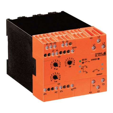
DOLD MINISTART BL 9028 User manual

DOLD

DOLD MINISTART BL 9028 User manual

DOLD MINISTART BL 9228 User manual

DOLD

DOLD MINISTART BL 9228 User manual

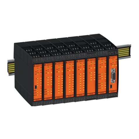
DOLD Safemaster Pro User manual

DOLD

DOLD Safemaster Pro User manual

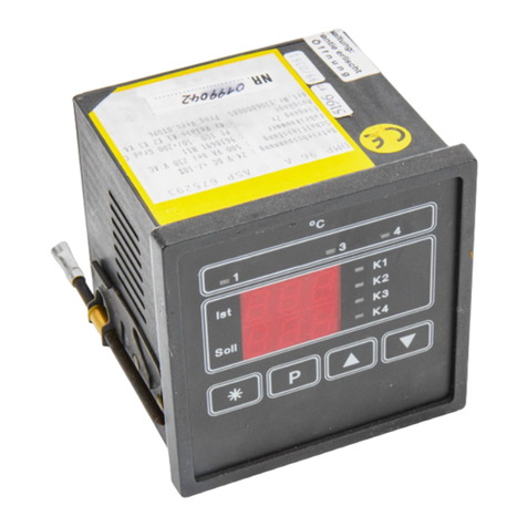
DOLD DMP 96 A User manual

DOLD

DOLD DMP 96 A User manual

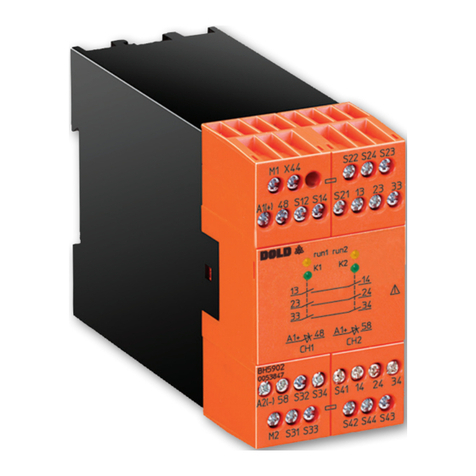
DOLD SAFEMASTER BH 5902/01MF2 User manual

DOLD

DOLD SAFEMASTER BH 5902/01MF2 User manual

DOLD Safemaster Pro User manual

DOLD

DOLD Safemaster Pro User manual

DOLD SAFEMASTER BH 5902/01MF2 Operating instructions

DOLD

DOLD SAFEMASTER BH 5902/01MF2 Operating instructions

DOLD SAFEMASTER BG 5925/900 Operating instructions

DOLD

DOLD SAFEMASTER BG 5925/900 Operating instructions

Popular Controllers manuals by other brands

WindowMaster WMS 309 Installation instructions manual

WindowMaster

WindowMaster WMS 309 Installation instructions manual

Oriental motor DGII Series manual

Oriental motor

Oriental motor DGII Series manual

afx light DC-54DMX instruction manual

afx light

afx light DC-54DMX instruction manual

HQ Power VDPC146 user manual

HQ Power

HQ Power VDPC146 user manual

System air PULSER-M instructions

System air

System air PULSER-M instructions

Harmonic Drive FHA Mini Series manual

Harmonic Drive

Harmonic Drive FHA Mini Series manual

Contro l4 CA-10 installation guide

Contro l4

Contro l4 CA-10 installation guide

Astral Pool 66577 Installation, operation & maintenance manual

Astral Pool

Astral Pool 66577 Installation, operation & maintenance manual

Oriental motor alphaSTEP ARL Series Setting manual

Oriental motor

Oriental motor alphaSTEP ARL Series Setting manual

Landi Renzo CN04 Installation and adjustment manual

Landi Renzo

Landi Renzo CN04 Installation and adjustment manual

Phase Technologies ES Series quick start guide

Phase Technologies

Phase Technologies ES Series quick start guide

HySecurity StrongArm M30 Programming & operation manual

HySecurity

HySecurity StrongArm M30 Programming & operation manual

Oriental motor DH Series operating manual

Oriental motor

Oriental motor DH Series operating manual

Goldline aqua trol user manual

Goldline

Goldline aqua trol user manual

foc.us CommandPost user guide

foc.us

foc.us CommandPost user guide

Global American Inc. 3307980 user manual

Global American Inc.

Global American Inc. 3307980 user manual

COLORKINETICS AuxBox installation instructions

COLORKINETICS

COLORKINETICS AuxBox installation instructions

Timeguard PDFM1500N Installation & operating instructions

Timeguard

Timeguard PDFM1500N Installation & operating instructions

manuals.online logo
manuals.online logoBrands
  • About & Mission
  • Contact us
  • Privacy Policy
  • Terms and Conditions

Copyright 2025 Manuals.Online. All Rights Reserved.