ECS 945GCD-I230 User manual


Preface
Preface
Copyright
This publication, including all photographs, illustrations and software, is protected
under international copyright laws, with all rights reserved. Neither this manual, nor
any of the material contained herein, may be reproduced without written consent of
the author.
Version 1.0
Disclaimer
The information in this document is subject to change without notice. The manufac-
turer makes no representations or warranties with respect to the contents hereof and
specifically disclaims any implied warranties of merchantability or fitness for any
particular purpose. The manufacturer reserves the right to revise this publication and
to make changes from time to time in the content hereof without obligation of the
manufacturer to notify any person of such revision or changes.
TrademarkRecognition
Microsoft, MS-DOS and Windows are registered trademarks of Microsoft Corp.
MMX, Pentium, Pentium-II, Pentium-III, Celeron are registered trademarks of Intel
Corporation.
Other product names used in this manual are the properties of their respective
owners and are acknowledged.
FederalCommunicationsCommission(FCC)
This equipment has been tested and found to comply with the limits for a Class B
digital device, pursuant to Part 15 of the FCC Rules. These limits are designed to
provide reasonable protection against harmful interference in a residential installa-
tion. This equipment generates, uses, and can radiate radio frequency energy and, if
not installed and used in accordance with the instructions, may cause harmful inter-
ference to radio communications. However, there is no guarantee that interference
will not occur in a particular installation. If this equipment does cause harmful
interference to radio or television reception, which can be determined by turning the
equipment off and on, the user is encouraged to try to correct the interference by one
or more of the following measures:
• Reorient or relocate the receiving antenna
• Increase the separation between the equipment and the receiver
• Connect the equipment onto an outlet on a circuit different from that to
which the receiver is connected
• Consult the dealer or an experienced radio/TV technician for help
Shielded interconnect cables and a shielded AC power cable must be employed with
this equipment to ensure compliance with the pertinent RF emission limits govern-
ing this device. Changes or modifications not expressly approved by the system’s
manufacturer could void the user’s authority to operate the equipment.

ii
Preface
DeclarationofConformity
This device complies with part 15 of the FCC rules. Operation is subject to the
following conditions:
• This device may not cause harmful interference, and
• This device must accept any interference received, including interfer-
ence that may cause undesired operation
CanadianDepartmentofCommunications
This class B digital apparatus meets all requirements of the Canadian Interference-
causing Equipment Regulations.
Cet appareil numérique de la classe B respecte toutes les exigences du Réglement sur
le matériel brouilieur du Canada.
AbouttheManual
The manual consists of the following:
Chapter 1
Introducing the Motherboard
Chapter 2
Installing the Motherboard
Chapter 3
UsingBIOS
Chapter 4
Using the Motherboard Software
Describes features of the
motherboard.
Go to Hpage 1
Describes installation of
motherboard components.
Goto Hpage 7
Provides information on us-
ing the BIOS Setup Utility.
Go to Hpage 23
Describes the motherboard
software
Go to Hpage 39

iii
TT
TT
TABLE OF CONTENTSABLE OF CONTENTS
ABLE OF CONTENTSABLE OF CONTENTS
ABLE OF CONTENTS
Preface i
Chapter 1 1
IntroducingtheMotherboard 1
Introduction......................................................................................1
Feature...............................................................................................2
MotherboardComponents.............................................................4
Chapter 3 23
UsingBIOS 23
Aboutthe SetupUtility................................................................23
The Standard Configuration...................................................23
Entering the Setup Utility........................................................23
Resetting the Default CMOS Values.......................................24
UsingBIOS......................................................................................25
Standard CMOS Setup...........................................................26
Advanced Setup......................................................................28
Advanced Chipset Setup.........................................................29
Chapter 2 77
77
7
Installing the Motherboard 7
SafetyPrecautions...........................................................................7
Choosinga ComputerCase............................................................7
Installingthe Motherboard in a Case............................................7
CheckingJumperSettings...............................................................8
Setting Jumpers........................................................................8
Checking Jumper Settings........................................................9
Jumper Settings........................................................................9
InstallingHardware........................................................................10
Installing Memory Modules...................................................10
Expansion Slot........................................................................12
Connecting Optional Devices................................................14
Installing a Hard Disk Drive/CD-ROM/SATA Hard Drive...16
ConnectingI/ODevices................................................................18
ConnectingCase Components.....................................................19
Front Panel Header................................................................21

iv
Integrated Peripherals............................................................30
Power Management Setup......................................................32
PCI/PnP Setup........................................................................33
PC Health Status....................................................................34
Frequency/Voltage Control.....................................................34
Load Default Settings.............................................................35
Supervisor Password.............................................................35
User Password.......................................................................36
Save & Exit Setup....................................................................36
Exit Without Saving.................................................................36
Updating the BIOS..................................................................37
Chapter 4 3939
3939
39
UsingtheMotherboardSoftware 39
Aboutthe SoftwareCD-ROM......................................................39
Auto-installingunderWindows XP/Vista..................................39
Running Setup.........................................................................40
ManualInstallation........................................................................44
UtilitySoftwareReference............................................................44

1
IntroducingtheMotherboard
Chapter1
IntroducingtheMotherboard
Introduction
Thank you for choosing the 945GCD-I230 motherboard of great performance and
with enhanced function. The motherboard has onboard Intel Diamondville CPU with
a Mini-ITX form factor of 170 x 170 mm.
The motherboard incorporates the 945GC Northbridge (NB) and ICH7 Southbridge
(SB) chipsets. The Northbridge supports a Front Side Bus (FSB) frequency of 533
MHz using a scalable FSB Vcc_CPU. The memory controller supports DDR2 memory
DIMM frequency of 533. It supports one DDR2 socket with up to maximum memory
of 2GB.
The ICH7 Southbridge supports one PCI slot which is PCI 2.3 compliant. It imple-
ments an EHCI compliant interface that provides 480 Mb/s bandwidth for 8 USB 2.0
ports (4 USB ports and 2 USB 2.0 headers support additional 4 USB ports). The
Southbridge integrates a Serial ATA host controller, supporting two SATA ports with
maximum transfer rate up to 3.0 Gb/s each.
The motherboard is equipped with advanced full set of I/O ports in the rear panel,
including PS/2 mouse and keyboard connectors, COM, LPT1, one VGA port, four
USB ports, one LAN port and audio jacks for microphone, line-in and line-out.

2
IntroducingtheMotherboard
Feature
• Onboard IntelAtom (Diamondville) single core, 1.60GHz CPU speed
with 512KB cache
• Supports a system bus (FSB) of 533 MHz
• Supports “Hyper-Threading” technology CPU
This motherboard uses onboard Intel Diamondville CPU that carries the follow-
ing features:
Processor
The 945GC Northbridge (NB) and ICH7 Southbridge (SB) chipsets are based on
an innovative and scalable architecture with proven reliability and performance.
Chipset
ICH7 (SB) • EnhancedDMAcontroller, interrupt controller,and timer
functions
• Compliant with PCI 2.3 specification
• Integrated SATA 3.0 Gb/s Host Controller
• Integrated USB 2.0 Host Controller supporting up to
eight USB 2.0 ports
• Integrated IDE controller supports Ultra ATA 100/66
• SupportsDDR2 533 DDR2 SDRAM
•Accommodates one unbuffered DIMM
• Up to 2 GB per DIMM with maximum memory size up to 2 GB
Memory
945GC (NB) • Supports 32-bit host bus addressing
• 2 GB/s point-to-point Direct Media Interface (DMI) to
ICH7 (1 Gb/s each direction)
• Supports 256-Mb, 512-Mb and 1-Gb DDR2 technolo-
gies for x8 and x16 devices
• Supports High-Quality 3D setup, Render Engine and
High-Quality Texture Engine
“Hyper-Threading” technology enables the operating system into thinking it’s
hooked up to two processors, allowing two threads to be run in parallel, both on
separate “logical” processors within the same physical processor.
Audio
• 5.1 Channel High DefinitionAudio Codec
• Exceeds Microsoft Windows Logo Program (WLP) Requirements
• ADCs support 44.1K/48K/96K/192KHz sample rate
• Power Support: Digital: 3.3V; Analog: 5.0V
The onboard Audio provides the following features:

3
IntroducingtheMotherboard
Onboard LAN
The onboard LAN controller provides the following features:
The motherboard comes with the following expansion options:
• One 32-bit PCI v2.3 compliant slot
• One IDE connector that supports two IDE devices
• Two 7-pin SATA connectors
The motherboard supports UDMA bus mastering with transfer rates of 100/66 Mb/
s.
Expansion Options
Integrated I/O
BIOS Firmware
• Two PS/2 ports for mouse and keyboard
• One serial port
• One LPT port
• One VGA port
• Four USB ports
• One LAN port
• Audio jacks for microphone, line-in and line-out
The motherboard has a full set of I/O ports and connectors:
This motherboard uses AMI BIOS that enables users to configure many system
features including the following:
• Power management
• Wake-up alarms
• CPUparameters
• CPUandmemorytiming
1. Some hardware specifications and software items are subject to change
without prior notice.
2. Due to chipset limitation, we recommend that motherboard be oper-
ated in the ambiance between 0 and 50 °C.
3. To achieve better performance and air flow, we suggest that you use a
system fan on this motherboard.
• Supports 10/100 Mbps Ethernet transceiver
• Fullycompliant withIEEE 802.3,IEEE 802.3u, IEEE 802.3ab
• Wake-On-LAN (WOL) by Magic Packet/Frame/Link Change
The firmware can also be used to set parameters for different processor clock speeds.
4
IntroducingtheMotherboard
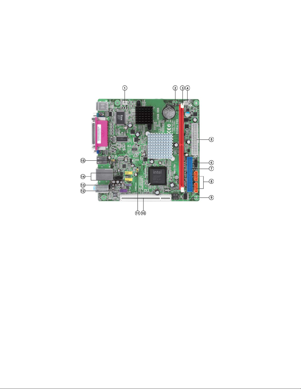
MotherboardComponents
5
IntroducingtheMotherboard
Table of Motherboard Components
LABEL COMPONENTS
1. SYS_FAN System cooling fan connecto
r
2. CLR_CMOS Clear CMOS
j
umpe
r
3. DDR2 240-pin DDR2 SDRAM slot
4. PWR_FAN Power coolin
g
fan connecto
r
5. ATX1 Standard 24-pin ATX power connecto
r
6. F_PANEL Front panel switch/LED heade
r
7. IDE Primary IDE connector
8. SATA1~2 Serial ATA connectors
9. SP
K
Internal s
p
eaker header
10. PCI 32-bit add-on card slot
11. USBPWR_F Front panel USB Power Select
j
umpe
r
12. F_AUDIO Front panel audio header
13. SPDIFO SPDIF out heade
r
14. F_USB1~2 Front panel USB headers
15. USBPWR_R Rear USB/PS2 Power Select jumper
This concludes Chapter 1. The next chapter explains how to install the motherboard.

6
IntroducingtheMotherboard
Memo

7
InstallingtheMotherboard
Chapter2
InstallingtheMotherboard
SafetyPrecautions
• Follow these safety precautions when installing the motherboard
• Wear a grounding strap attached to a grounded device to avoid dam-
age from static electricity
• Discharge static electricity by touching the metal case of a safely
grounded object before working on the motherboard
• Leave components in the static-proof bags they came in
• Hold all circuit boards by the edges. Do not bend circuit boards
ChoosingaComputerCase
There are many types of computer cases on the market. The motherboard complies
with the specifications for the Mini-ITX system case. First, some features on the
motherboard are implemented by cabling connectors on the motherboard to indica-
tors and switches on the system case. Make sure that your case supports all the
features required. Secondly, this motherboard supports two enhanced IDE drives.
Make sure that your case has sufficient power and space for all drives that you intend
to install.
Most cases have a choice of I/O templates in the rear panel. Make sure that the I/O
template in the case matches the I/O ports installed on the rear edge of the
motherboard.
This motherboard carries a Mini-ITX form factor of 170 x 170 mm. Choose a case
that accommodates this form factor.
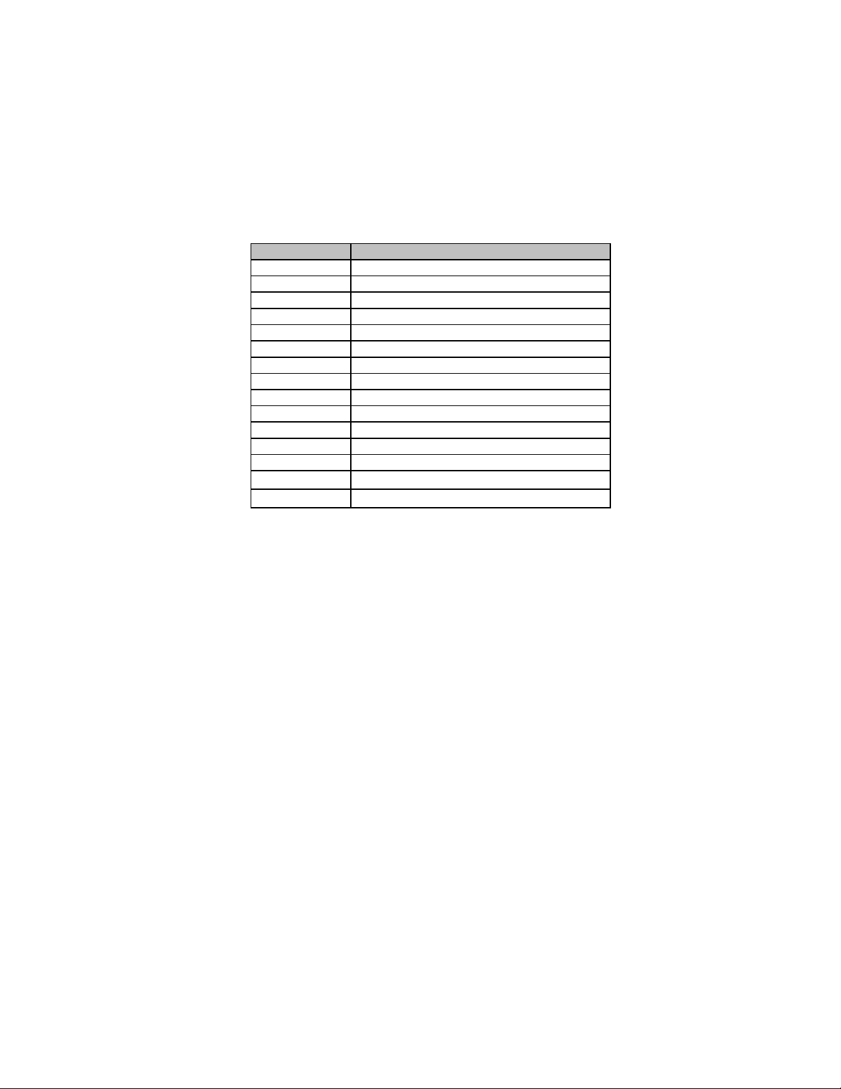
InstallingtheMotherboardina Case
Refer to the following illustration and instructions for installing the motherboard in
a case.
Most system cases have mounting brackets installed in the case, which correspond
the holes in the motherboard. Place the motherboard over the mounting brackets
and secure the motherboard onto the mounting brackets with screws.
Ensure that your case has an I/O template that supports the I/O ports and expansion
slots on your motherboard.
8
InstallingtheMotherboard
CheckingJumperSettings
This section explains how to set jumpers for correct configuration of the motherboard.
SettingJumpers
Use the motherboard jumpers to set system configuration options. Jumpers with
more than one pin are numbered. When setting the jumpers, ensure that the jumper
caps are placed on the correct pins.
The illustrations show a 2-pin jumper. When
the jumper cap is placed on both pins, the
jumper is SHORT. If you remove the jumper
cap, or place the jumper cap on just one pin,
the jumper is OPEN.
This illustration shows a 3-pin jumper. Pins
1 and 2 are SHORT.
SHORT OPEN
Do not over-tighten the screws as this can stress the motherboard.

9
InstallingtheMotherboard
Checking Jumper Settings
The following illustration shows the location of the motherboard jumpers. Pin 1 is
labeled.
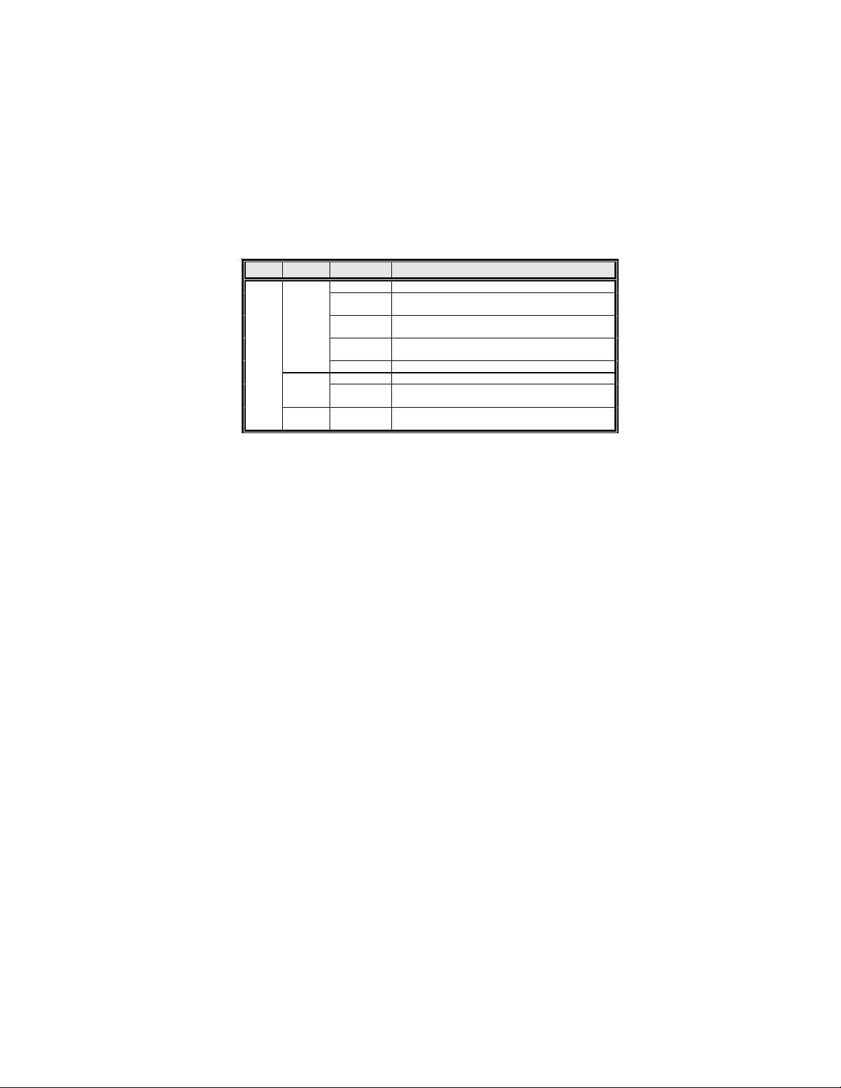
JumperSettings
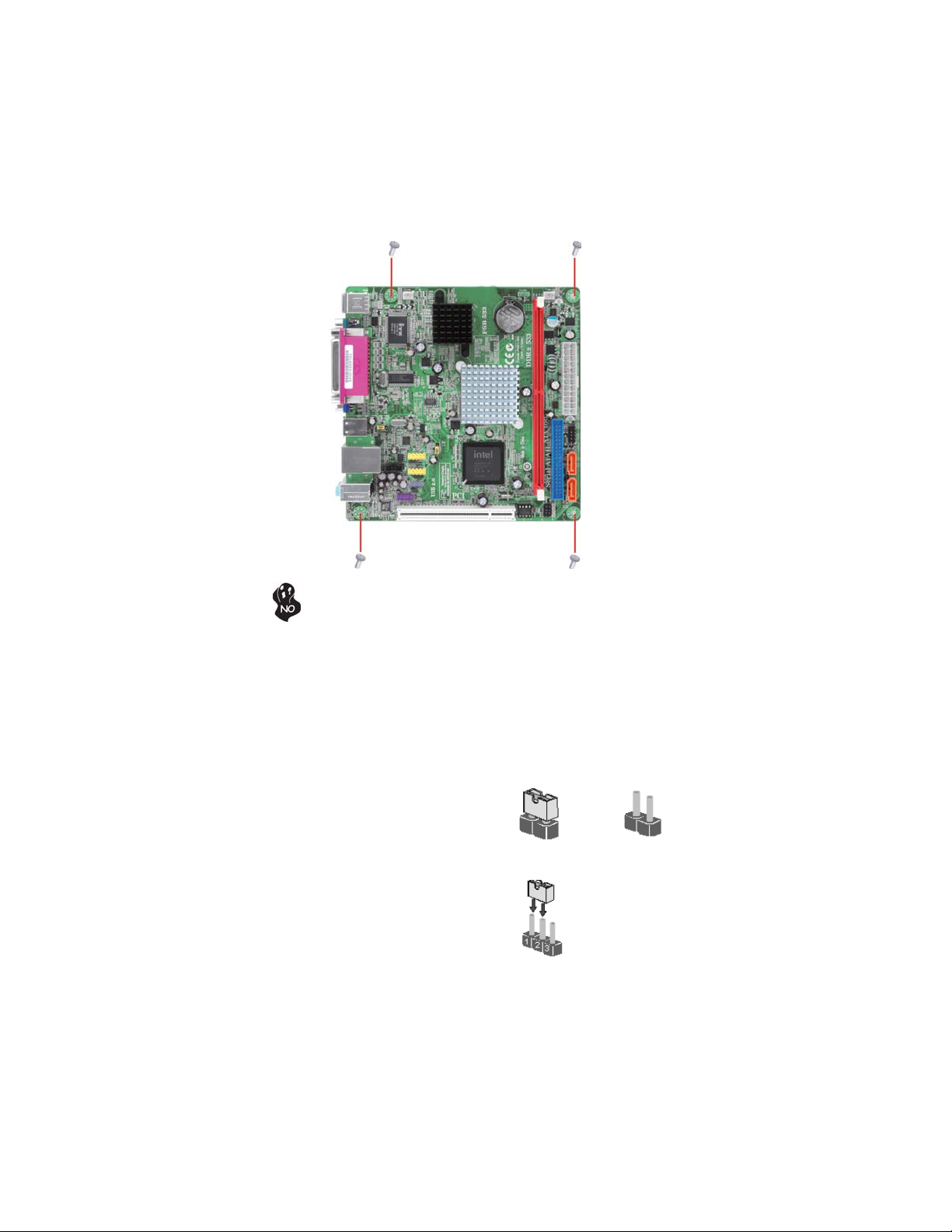
To avoid the system instability after clearing CMOS, we recommend
users to enter the main BIOS setting page to “Load Default Settings”
and then “Save & Exit Setup”.
1.
2. Make sure the power supply provides enough 5VDUAL voltage before
selecting the 5VDUAL function.
3. It is required that users place the USBPWR_F & USBPWR_R cap onto
2-3 pin rather than 1-2 pin as default if you want to wake up the com-
puter by USB/PS2 KB/Mouse.
Jumper Type Description Setting (default)
CLR_CMOS 3-pin CLEAR CMOS
1-2: NORMAL
2-3: CLEAR CMOS
Before clearing the
CMOS, make sure to
turn the system off.
3-pin
USBPWR_R
1-2: VCC
2-3: 5VDUAL
Rear USB/PS2
Power Select
Jumper
3-pin
USBPWR_F
1-2: VCC
2-3: 5VDUAL
Front Panel
USB Power
Select Jumper
USBPWR_R
CLR_CMOS
1
1
USBPWR_F
1
10
InstallingtheMotherboard
This motherboard accommodates one memory module. It can support one 240-pin
DDR2 533. The total memory capacity is 2 GB.
Do not remove any memory module from its antistatic packaging
until you are ready to install it on the motherboard. Handle the
module only by its edge. Do not touch the components or metal
parts. Always wear a grounding strap when you handle the module.
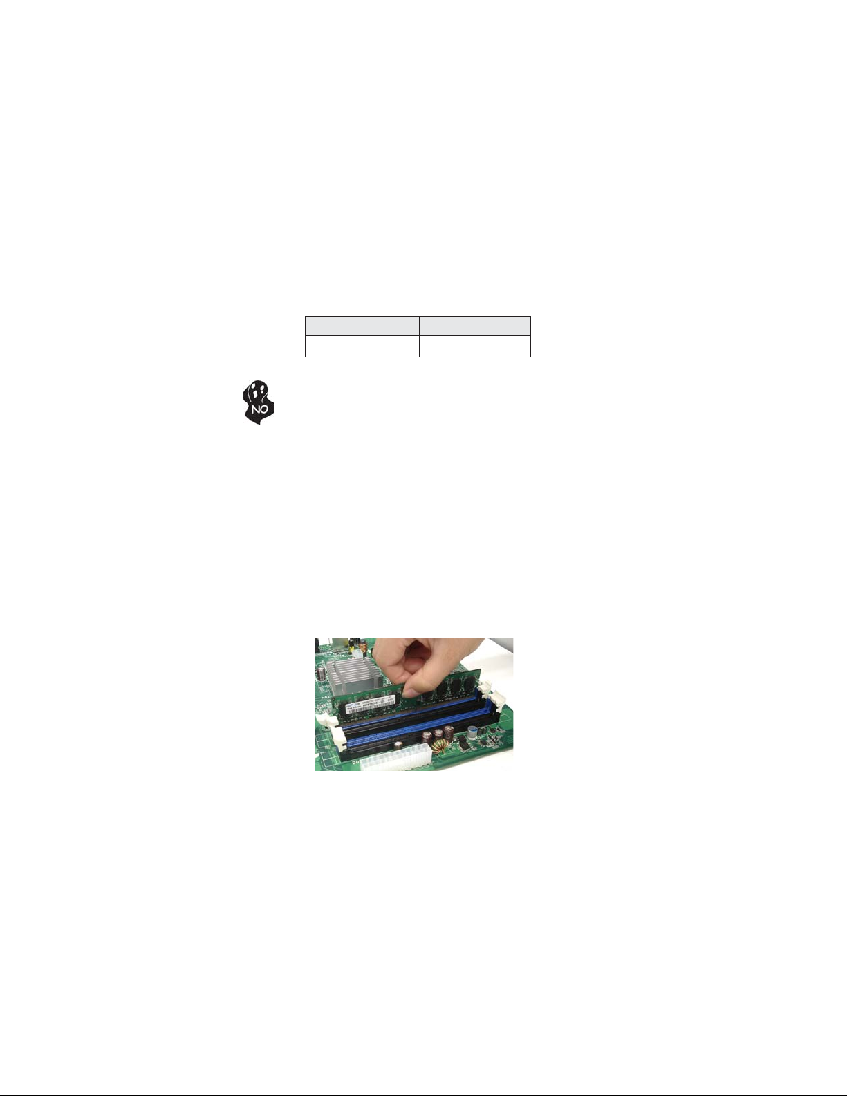
Installation Procedure
Refer to the following to install the memory modules.
1 This motherboard supports unbuffered DDR2 SDRAM .
2 Push the latches on each side of the DIMM slot down.
3 Align the memory module with the slot. The DIMM slot is keyed with
notches and the DIMM is keyed with cutouts so that it can only be
installed correctly.
4 Check that the cutouts on the DIMM module edge connector match the
notches in the DIMM slot.
5 Install the DIMM module into the slot and press it firmly down until it
seats correctly. The slot latches are levered upwards and latch on to
the edges of the DIMM.
DDR2 SDRAM memory module table
DDR2 533 266 MHz
Memory module Memory Bus
InstallingHardware
Installing Memory Modules
11
InstallingtheMotherboard
Table A: DDR2 (memory module) QVL (Qualified Vendor List)
The following DDR2 533 memory modules have been tested and qualified for use
with this motherboard.
Type Size Vendor Module Name
Aeneon Aeneon AET93F370 SS 512MB
Corsair VS512MB533D2/Corsair/64M8CEC/512MB/
SS
Infineon Infineon HY818T512800AF37 33346778
512MB
Kingston KVR533D2S4/Nanya/NT5TU64M8AE-
37B/512MB/SS
512 MB
Ramaxel Ramaxel 6AD11 D9GCT 512MB
Kingmax KKEA88E4AAKG-37
1 GB Samsung 1GB PC2-4200U-444-12-
E3/Samsung/K4T51083QC/1GB/DS
DDR2
533
2GB Micron
2GB PC2-4200U-444-12-E0

12
InstallingtheMotherboard
Before installing an add-on card, check the documentation for the
card carefully. If the card is not Plug and Play, you may have to
manually configure the card before installation.
This motherboard is equipped with one standard PCI slot. PCI stands
for Peripheral Component Interconnect and is a bus standard for ex-
pansion cards, which for the most part, is a supplement of the older
ISA bus standard. The PCI slot on this board is PCI v2.3 compliant.
PCI Slot
The slot on this motherboard is designed to hold expansion card and connect it to the
system bus. Expansion slot is a means of adding or enhancing the motherboard’s
features and capabilities. With this efficient facility, you can increase the
motherboard’s capabilities by adding hardware that performs tasks that are not part
of the basic system.
Expansion Slot
Installing Add-on Card

13
InstallingtheMotherboard
Follow these instructions to install an add-on card:
1 Remove a blanking plate from the system case corresponding to the
slot you are going to use.
2 Install the edge connector of the add-on card into the expansion slot.
Ensure that the edge connector is correctly seated in the slot.
3 Secure the metal bracket of the card to the system case with a screw.
2. The onboard PCI interface does not support 64-bit SCSI cards.
1. For some add-on cards, for example graphics adapters and network
adapters, you have to install drivers and software before you can begin
using the add-on card.

14
InstallingtheMotherboard
Connecting Optional Devices
Refer to the following for information on connecting the motherboard’s optional
devices:
SATA1~2: Serial ATA connectors
These connectors are used to support the new Serial ATA devices for the highest data
transfer rates (3.0 Gb/s), simpler disk drive cabling and easier PC assembly. It elimi-
nates limitations of the current Parallel ATA interface. But maintains register com-
patibility and software compatibility with Parallel ATA.
1Ground 2TX+
3TX- 4Ground
5RX- 6RX+
7Ground --
Pin Signal Name
Pin Signal Name
SPDIFO:SPDIF out header
This is an optional header that provides an S/PDIF (Sony/Philips Digital Interface)
output to digital multimedia device through optical fiber or coaxial connector.
2+5VA 5V analog Power
3 Key No pin
4GND Ground
Pin Signal Name Function
1SPDIF SPDIF digital output
Table of contents
Other ECS Motherboard manuals


Popular Motherboard manuals by other brands

Texas Instruments
Texas Instruments AM62x SK EVM user guide

Asus
Asus Motherboard A7N8X-VM user manual

Silicon Laboratories
Silicon Laboratories Si5040 user manual

VersaLogic
VersaLogic Bengal VL-EPMe-30 Hardware reference manual

Geniatech
Geniatech DB8 manual

Cypress
Cypress CYW920735Q60EVB-01 quick start guide


