A-Trend ATC-5030 User manual

Table of Contents
JUMPER COMPONENT LOCATION DIAGRAM.................A
CHAPTER 1 INTRODUCTION..........................................2
1-1 System features..................................................................3
1-2 S ftware p wer ff c ntr l..................................................4
1-3 Check list f the packing.....................................................5
1-4 Wake-On-LAN………………………………………………….6
CHAPTER 2 INSTALLATION...........................................7
2-1 Installati n pr cedures .......................................................7
2-2 CPU installati n..................................................................8
2-3 System mem ry installati n................................................20
2-4 SRAM installati n................................................................22
2-5 Other jumpers and c nnect rs
descripti n .........................................................................23
2-6 IDE driver installati n..........................................................28
CHAPTER 3 AWARD BIOS SETUP.................................2
3-1 Update BIOS pr cedures....................................................30
3-2 Award system BIOS c nfigurati n setup............................31
APPENDIX A ......................................................................56

CHAPTER 1 INTRODUCTION
Thank f r y u purchasing the ATC-5030 mainb ard, up n purchas-
ing this pr duct fr m the supplier, r any f its distribut rs, vend rs
l cal dealers, y u are qualified f r ne year warranty.
This manual describes t c nfigure the ATC-5030 mainb ard f r
different envir nments. It's an verview f the lay ut and features
f the ATC-5030 mainb ard, and als pr vides inf rmati n f r y u
t change the c nfigurati n r system envir nment.
This manual is divided int tw secti ns :
PART ONE includes page A and tw chapters as f ll wing:
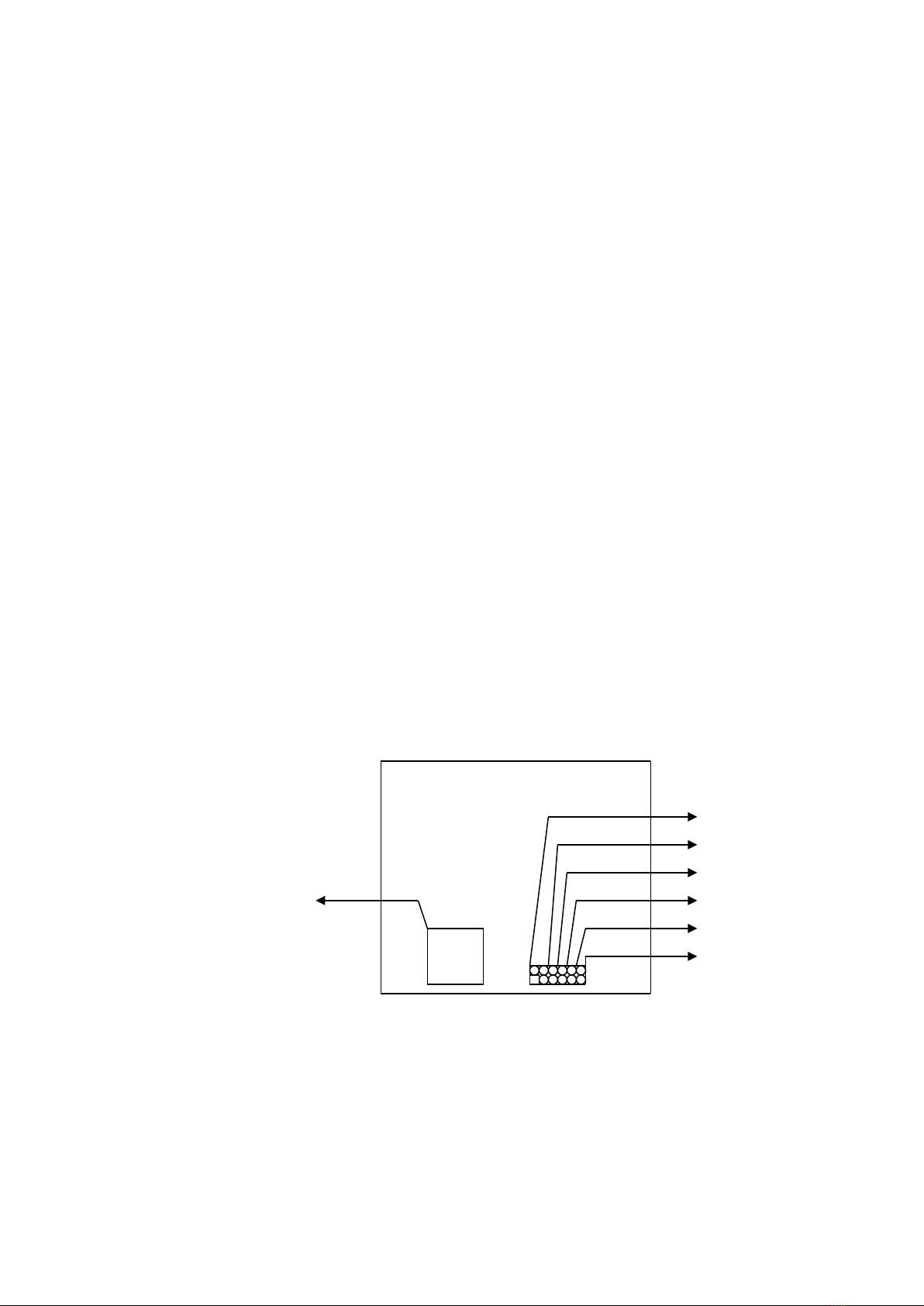
Page A c ntains lay ut diagram f the mainb ard.
Please refer t it when y u c nfigure the system.
Chapter 1 is an verview f the ATC-5030 mainb ard features
and packing items.
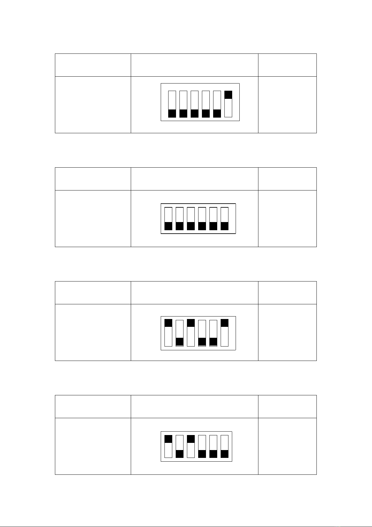
Chapter 2 describes h w t upgrade and t change hardware
c nfigurati ns such as mem ry size, CPU type, and
the lists f jumper settings and c nnect rs.
PART TWO includes chapter 3 which c ntains Award BIOS
descripti n..
Chapter 3 is the user's guide f the Award BIOS setup utility and
Flash ROM BIOS. The menu is sh wn in this chapter
will be indicated the value f the default settings.
Y ur system dealer will set up the ATC-5030 mainb ard acc rding
t y ur demand f the c mputer. It means that the current settings f
y ur ATC-5030 mainb ard may n t be the same as the defaults sh wn
in this user's manual. If y u need t change y ur c nfigurati n, please
ask y ur dealer first. Be sure this will n t v id y ur system warranty, r
ask y ur dealer t d it f r y u.
REMARK
Intel® is a registered trademark f Intel C rp rati n.
All ther brands and pr duct names are trademarks registered trademarks f their respective
c mpanies.
2

1-1 SYSTEM FEATURES
Supp rts Intel Pentium (P54C) CPU perating at 90MHz t
200MHz & Intel Pentium MMXTM 166~233MHz (P55C), AMD
K5, AMD K6, Cyrix 6x86MXTM, 6x86L.
INTEL 430TX PCIset.
Using f ur 72-pin SIMM s ckets, pr vides tw banks f 64-bit
wide path up t 256MB addressing page m de DRAMs.
Using tw 168-pin DIMM s ckets f r 3.3V SDRAM r 3.3V
EDO DRAM m dule.
Built-in 512KB PB SRAM n b ard
Supp rting f ur PCI bus master revisi n 2.1, 5V interface
c mpliant and three 16-bit ISA sl ts.
Dual Master IDE c nnect rs supp rt Ultra UMA/33 (33MB/sec
transfer rate), up t f ur devices in tw channels f r c nnecti n
f high capacity hard disk drive, CD-ROM, tape backup etc..
AT style keyb ard c nnect r and header.
The Ultra Multi-I/O chipset, integrated Keyb ard c ntr ller.
Supp rting Infrared transfer (IrDA TX/RX) c nnecti n.
One FDC p rt supp rts tw devices up t 2.88MB
Tw 16550A fast UARTs c mpatiable serial p rts
One EPP/ECP m de parallel p rt
Supp rting Dual channel USB c nnecti n.
Built-in Switching V ltage Regulat r
Supp rts ACPI P wer Management - OSPM (OS directed
p wer management)
ATX and AT p wer c nnect r
PCB Dimensi n is 220mm x 230mm (8.66" x 9.0") with f ur
layers designed.
3

1-2 SOFT-OFF CONTROL (option)
The ATC-5030 mainb ard design supp rts S ft-Off C ntr l
feature thr ugh the SMM c de in the BIOS under Wind ws 95,
Wind ws 3.1x, and MS-DOS perati n system envir nment. It
needs t use ATX p wer supply. (please c ntact y ur supplier f r
this pti n)
Firstly, y u sh uld c nnect p wer switch cable (pr vided by ATX
case supplier) t the PS_ON (CONN1) (next t FAN & s cket 7 )
n the ATC-5030 mainb ard.
In Wind ws 95, if y u w uld like t s ft p wer ff the system,
y u just ch se “shutd wn the c mputer ?” in “Shut D wn
Wind ws“ fr m Wind ws 95, then push the P wer Switch* ( n
ATX case), then system will be in s ft ff status directly. If y u
w uld like t restart the system, just press the butt n f the p wer
switch, and the system will be p wer n.
* Default value (P wer management f BIOS screen) is “Instant-
ff‘, y u can change t ’Delay 4 Sec.‘, then y u sh uld push the
P wer Switch at least 4 sec nds therwise the system will be
under SMI m de nly.
In Wind ws 3.1x r MS-DOS, y u sh uld c py the pr gram f
“d wn.c m” (y u can find it in the diskette f IDE driver) int hard
drive. When y u w uld like t p wer ff the system, just run this
“down.com”, then the system will be shutd wn and stay in
standby status.
PS_ON
CONN1 FAN
CPU
N te : If y u will leave y ur system several days, we suggest y u
use hardware mechanical p wer ff t shutd wn y ur system.
4

1-3 CHECK LIST OF THE PACKING
The ATC-5030 mainb ard c mes securely packed in a durable
b x and shipping cart n. If any f the ab ve items are missing r
damaged, please c ntact y ur supplier.
Each ATC-5030 mainb ard c ntaining:
Q'TY Descripti n
1 Mainb ard : ATC-5030.
1 Diskette : Enhanced IDE driver (3.5").
Award system BIOS driver
Update Utility
1 Cable : Enhanced IDE c nnect r.
1 Cable : F.D.D. c nnect r.
1 Cable : Serial p rt.
1 Cable : Serial/Parallel.
1 Manual : User`s manual.
NOTE : Leave the ATC-5030 mainb ard in its riginal packing until
y u are ready t install it.
5

1-5 Wake-On-LAN
The rem te Wake-On-LAN m de f perati n is a mechanism
that uses Advanced Micr Device Magic Packet techn l gy t
p wer up a sleeping w rkstati n n the netw rk. This mechanism
is acc mplished when the LAN card receives a specific packet f
inf rmati n, called a Magic Packet, addressed t then de n the
netw rk. F r additi nal pr tecti n, Secure ON is an pti nal
security feature that can be added t the Magic Packet that
requires a passw rd t p wer up the sleeping w rkstati n. When
the LAN card is in rem te Wake-On-LAN m de, main system
p wer can be shut d wn leaving p wer nly f r the LAN card and
auxiliary p wer rec nditi n.
The LAN card perf rms n netw rk activities while in the rem te
Wake-On-LAN m de f perati n-It nly m nit rs the netw rk f r
receipt f a Magic Packet. If a Magic Packet is addressed t the
LAN card n the netw rk, the LAN card wake up the system. If the
Secure ON feature has been enabled, the passw rd added t the
Magic Packet is als verified pri r t waking up the system.
Y u sh uld select the LAN card als supp rt WOL functi n.
WOL has tw pr t c l . That are INTEL and DEC. JP7 is set t
rec ngize y ur LAN card is INTEL r DEC pr t c l.
WOL LAN card will pr vide a 3-pin line t c nnect the WOL
c nnect r n the mainb ard.
WOL JP7
INTEL 1-2
DEC 2-3
6

CHAPTER 2 INSTALLATION
2-1 INSTALLATION PROCEDURE
Bef re installing the c mputer, please prepare all c mp nents
such as CPU, DRAM; peripherals such as hard disk devices,
keyb ard, CD-ROM drive; and access ries such as cables. Then,
install the system as f ll wing :
1. Plug CPU, heat sink, c ling fan, and DRAM m dules in
the ATC-5030 mainb ard.
2. Set jumpers based n y ur c nfigurati n.
3. Plug add- n cards in PCI/ISA sl ts.
4. C nnect cables t peripherals, p wer supply..
5. Make sure all c mp nents and devices are well
c nnected, turn n the p wer and setup System BIOS
based n y ur c nfigurati n.
6. Install peripheral, add- n card drivers and test them.
7. If all f ab ve pr cedures are success, turn- ff the p wer
then plug all f them int y ur c mputer case.
7

2-2 CPU INSTALLATION
ATC-5030 supports one Pentium level CPU.
It can aut detect CPU v ltage value either single r dual CPU
v ltage p wer supply type with ut jumper setting. F r installati n,
please n tice CPU pin 1 must align with the ZIF s cket 7 Pin 1
l cati n. Bef re y u install r upgrade y ur CPU, please read
CPU guide fr m CPU manufacturer t make sure the CPU
specificati n. Then ch se the right installati n in secti n 2-2-1
based n y ur CPU type/brand and f ll w the descripti n t setup
DIP Switch (SW1). If y ur CPU is n t in the list f 2-2-1, please
refer t 2-2-2 and 2-2-3 f r installati n. The ATC-5030 mainb ard
pr vides aut -detecti n functi n t detect CPU c re v ltages and
CPU c re v ltages range fr m 2.1V t 3.5V.
8

2-2-1 CPU TYPE SELECTION
The DIP switch 1 on the ATC-5030 motherboard is to adjust
the CPU internal clocks by using external CPU frequencies
techniques for all brands of the CPU.
A. INTEL PENTIUM CPU (P54C)
※ P54C VRE : 3.400V ~ 3.600V (The f urth line f the mark n the
under-side f the pr cess r c ntains a c de that identifies
the v ltage level type. V is VRE, S is standard. )
※ P54C STD : 3.135V ~ 3.600V (The f urth line f the mark n the
under-side f the pr cess r c ntains a c de that identifies
the v ltage level type. V is VRE, S is standard. )
JP14
JP13
JP12
CPU JP11
JP10
SW1 JP
9

Intel Pentium 90MHz
INTERNAL CPU
CLOCK
SW1 Ext.x Frq.
90MHz
ON
OFF
1 2 3 4 5 6
60 x 1.5
Intel Pentium 100MHz
INTERNAL CPU
CLOCK
SW1 Ext.x Frq.
100MHz ON
OFF
1 2 3 4 5 6
66 x 1.5
Intel Pentium 120MHz
INTERNAL CPU
CLOCK
SW1 Ext.x Frq.
120MHz ON
OFF
1 2 3 4 5 6
60 x 2.0
Intel Pentium 133MHz
INTERNAL CPU
CLOCK
SW1 Ext.x Frq.
133MHz
ON
OFF
1 2 3 4 5 6
66 x 2.0
10

Intel Pentium 150MHz
INTERNAL CPU
CLOCK
SW1 Ext.x Frq.
150MHz
ON
OFF
1 2 3 4 5 6
60 x 2.5
Intel Pentium 166MHz
INTERNAL CPU
CLOCK
SW1 Ext.x Frq.
166MHz ON
OFF
1 2 3 4 5 6
66 x 2.5
Intel Pentium 180MHz
INTERNAL CPU
CLOCK
SW1 Ext.x Frq.
180MHz ON
OFF
1 2 3 4 5 6
60 x 3.0
Intel Pentium 200MHz
INTERNAL CPU
CLOCK
SW1 Ext.x Frq.
200MHz ON
OFF
1 2 3 4 5 6
66 x 3.0
11

B. INTEL PENTIUM MMXTM CPU (P55C)
B-1. Intel Pentium MMX 166MHz
INTERNAL CPU
CLOCK
SW1 Ext.x Frq.
166MHz
ON
OFF
1 2 3 4 5 6
66 x 2.5
B-2. Intel Pentium MMX 200MHz
INTERNAL CPU
CLOCK
SW1 Ext.x Frq.
200MHz ON
OFF
1 2 3 4 5 6
66 x 3.0
B-3. Intel Pentium MMX 233MHz
INTERNAL CPU
CLOCK
SW1 Ext.x Frq.
233MHz ON
OFF
1 2 3 4 5 6
66 x 3.5
12

C. Cyrix 6x86(028) CPU
C-1. Cyrix 6x86MX PR150 @ 60 Bus 2x
INTERNAL CPU
CLOCK
SW1 Ext.x Frq.
PR150MHz
ON
OFF
1 2 3 4 5 6
60 x 2.0
C-2. Cyrix 6x86MX PR166 @ 66 Bus 2x
INTERNAL CPU
CLOCK
SW1 Ext.x Frq.
PR166MHz ON
OFF
1 2 3 4 5 6
66 x 2.0
C-3. Cyrix 6x86MX PR166 @ 60 Bus 2.5x
INTERNAL CPU
CLOCK
SW1 Ext.x Frq.
PR166MHz ON
OFF
1 2 3 4 5 6
60 x 2.5
13

C-4. Cyrix 6x86MX PR200 @ 66 Bus 2.5x
INTERNAL CPU
CLOCK
SW1 Ext.x Frq.
PR200MHz ON
OFF
1 2 3 4 5 6
66 x 2.5
C-5. Cyrix 6x86MX PR200 @ 75 Bus 2x
INTERNAL CPU
CLOCK
SW1 Ext.x Frq.
PR200MHz ON
OFF
1 2 3 4 5 6
75 x 2.0
C-6. Cyrix 6x86MX PR233 @ 75 Bus 2.5x
INTERNAL CPU
CLOCK
SW1 Ext.x Frq.
PR233MHz ON
OFF
1 2 3 4 5 6
75 x 2.5
14

D. Cyrix 6x86L CPU (dual voltage)
D-1. Cyrix 6x86L PR150+
INTERNAL CPU
CLOCK
SW1 Ext.x Frq.
PR150+MHz ON
OFF
1 2 3 4 5 6
60 x 2.0
D-2. Cyrix 6x86L PR166+
INTERNAL CPU
CLOCK
SW1 Ext.x Frq.
PR166+MHz ON
OFF
1 2 3 4 5 6
66 x 2.0
D-3. Cyrix 6x86L PR200+
INTERNAL CPU
CLOCK
SW1 Ext.x Frq.
PR200+MHz ON
OFF
1 2 3 4 5 6
75 x 2.0
15

E. AMD-K5 CPU Series
E-1. AMD-K5 PR 0
INTERNAL CPU
CLOCK
SW1 Ext.x Frq.
PR90MHz ON
OFF
1 2 3 4 5 6
60 x 1.5
E-2. AMD-K5 PR100
INTERNAL CPU
CLOCK
SW1 Ext.x Frq.
PR100MHz ON
OFF
1 2 3 4 5 6
66 x 1.5
E-3. AMD-K5 PR120
INTERNAL CPU
CLOCK
SW1 Ext.x Frq.
PR120MHz ON
OFF
1 2 3 4 5 6
60 x 2.0
16

E-4. AMD-K5 PR133
INTERNAL CPU
CLOCK
SW1 Ext.x Frq.
PR133MHz ON
OFF
1 2 3 4 5 6
66 x 2.0
E-5. AMD-K5 PR166
INTERNAL CPU
CLOCK
SW1 Ext.x Frq.
PR166MHz ON
OFF
1 2 3 4 5 6
60 x 2.5
F. AMD-K6 CPU
F-1. AMD-K6 166ALR
INTERNAL CPU
CLOCK
SW1 Ext.x Frq.
166 ALR (MHz) ON
OFF
1 2 3 4 5 6
66 x 2.5
17

F-2. AMD-K6 200 ALR
INTERNAL CPU
CLOCK
SW1 Ext.x Frq.
200 ALR (MHz) ON
OFF
1 2 3 4 5 6
66 x 3.0
F-3. AMD-K6-233 ANR CPU : 3.2V
INTERNAL CPU
CLOCK
SW1 Ext.x Frq.
233 ANR (MHz) ON
OFF
1 2 3 4 5 6
66 x 3.5
18

2-2-2 CPU Voltage, CPU Bus Clock and
Bus Freq. Ratio Setting
A. CPU Bus Clock :
Clock Gen. CPU Bus Clock: 6 Pin DIP-SW (Option) 2x6 Header
2x3 Header
BASE CLK SW1-6 (JP ) SW1-5 (JP10) SW1-4 (JP11)
60MHz ON OFF OFF
66MHz OFF OFF OFF
75MHz OFF ON OFF
83MHz ON ON ON
B. CPU Bus Frq.
Core/Bus Freq. Ratio: 6 Pin DIP-SW (Option) 2x6 Header
2x3 Header
RATE SW1-3 (JP12) SW1-2 (JP13) SW1-1 (JP14)
1.5x OFF OFF OFF
2.0x ON OFF ON
2.5x ON ON OFF
3.0x OFF ON OFF
3.5x OFF OFF OFF
4.0x ON OFF ON
4.5x ON ON ON
*Remark: JP14 is Only Useful AMD CPU ; Other Please set off
JP14
JP13
JP12
CPU JP11
JP10
JP
SW1
19

2-3 SYSTEM MEMORY INSTALLATION
ATC-5030 pr vides f ur 72-pin SIMM s ckets f r system
mem ry expansi n fr m 4MB t 256MB. These f ur SIMMs are
arranged t tw banks, Bank0 (SIM 1, 2) and Bank1(SIM 3, 4),
please refer t page A. Each bank pr vides 64-bit wide data path.
The mainb ard accepts Fast Page M de DRAM, and EDO
M de (Extended Data Out) DRAM, with a speed n sl wer than 70
nan sec nd. Y u sh uld plug DRAM m dules int tw s ckets
(same bank) r f ur s ckets at ne time. Each pair f m dules in
the same bank must be the same size, type, and speed; n matter
single-side r d uble-side m dule. Please plug in Bank 0 firstly if
y u nly have 2 m dules. The mainb ard supp rts mixing f EDO
and fast page m de DRAM am ng different banks, please plug
EDO in Bank 0.
Als this mainb ard pr vides tw pti nal 168-pin DIMM
s ckets f r 3.3V SDRAM r 3.3V EDO DRAM expansi n. Y u
sh uld plug SDRAM/DRAM m dule int each DIMM s ckets (as a
bank) r tw s ckets at ne time.
CAUTION: It‘s n t rec mmended t install the 3.3V SDRAM and
5V EDO r Fast Paged m de mem ry within a system. The 72-pin
DRAM cann t w rk with 168-pin DRAM in the same time.
Changing EDO/FPM DRAM t SDRAM, y u d n‘t have t adjust
jumper setting r BIOS value, n r change SDRAM t EDO/FPM
DRAM. (※ Please make sure the SDRAM plugged-in fully, t prevent c ntact
l ss.)
20
Table of contents
Other A-Trend Motherboard manuals

A-Trend
A-Trend ATC-2000 User manual

A-Trend
A-Trend ATC6240V User manual

A-Trend
A-Trend 6253M User manual

A-Trend
A-Trend atc-1020 User manual

A-Trend
A-Trend ATC5200M User manual

A-Trend
A-Trend ATC-6400 User manual

A-Trend
A-Trend 6241 User manual

A-Trend
A-Trend ATC-6230 User manual

A-Trend
A-Trend ATC-6260 User manual

A-Trend
A-Trend ATC-6320 User manual