ECS GF8200A User manual

Preface
Preface
Copyright
This publication, including all photographs, illustrations and software, is protected
under international copyright laws, with all rights reserved. Neither this manual, nor
any of the material contained herein, may be reproduced without written consent of
the author.
Version 1.0A
Disclaimer
The information in this document is subject to change without notice. The manufac-
turer makes no representations or warranties with respect to the contents hereof and
specifically disclaims any implied warranties of merchantability or fitness for any
particular purpose. The manufacturer reserves the right to revise this publication and
to make changes from time to time in the content hereof without obligation of the
manufacturer to notify any person of such revision or changes.
FederalCommunicationsCommission(FCC)
This equipment has been tested and found to comply with the limits for a Class B
digital device, pursuant to Part 15 of the FCC Rules. These limits are designed to
provide reasonable protection against harmful interference in a residential installa-
tion. This equipment generates, uses, and can radiate radio frequency energy and, if
not installed and used in accordance with the instructions, may cause harmful inter-
ference to radio communications. However, there is no guarantee that interference
will not occur in a particular installation. If this equipment does cause harmful
interference to radio or television reception, which can be determined by turning the
equipment off and on, the user is encouraged to try to correct the interference by one
or more of the following measures:
• Reorient or relocate the receiving antenna
• Increase the separation between the equipment and the receiver
• Connect the equipment onto an outlet on a circuit different from that to
which the receiver is connected
• Consult the dealer or an experienced radio/TV technician for help
Shielded interconnect cables and a shielded AC power cable must be employed with
this equipment to ensure compliance with the pertinent RF emission limits governing
this device. Changes or modifications not expressly approved by the system’s manu-
facturer could void the user’s authority to operate the equipment.
TrademarkRecognition
Microsoft, MS-DOS and Windows are registered trademarks of Microsoft Corp.
AMD, Athlon, Sempron, and Duron are registered trademarks of AMD Corporation.
Other product names used in this manual are the properties of their respective
owners and are acknowledged.

ii
Preface
DeclarationofConformity
This device complies with part 15 of the FCC rules. Operation is subject to the
following conditions:
• This device may not cause harmful interference, and
• This device must accept any interference received, including interfer-
ence that may cause undesired operation
CanadianDepartmentofCommunications
This class B digital apparatus meets all requirements of the Canadian Interference-
causing Equipment Regulations.
Cet appareil numérique de la classe B respecte toutes les exigences du Réglement sur
le matériel brouilieur du Canada.
AbouttheManual
The manual consists of the following:
Chapter 1
Introducing the Motherboard
Chapter 2
Installing the Motherboard
Chapter 3
UsingBIOS
Chapter 4
Using the Motherboard Software
Describes features of the
motherboard.
Go to Hpage 1
Describes installation of
motherboard components.
Goto Hpage 7
Provides information on us-
ing the BIOS Setup Utility.
Go to Hpage 29
Describes the motherboard
software
Go to Hpage 47
Chapter 5
SettingUp NVIDIARAIDConfiguration
Provides information about
SATARAIDSetup
Go to Hpage 57
Chapter 6
NVIDIA®®
®®
®HybridSLI®®
®®
®TechnologySupport
Provides information about
SATARAIDSetup
Go to Hpage 67

iii
TT
TT
TABLE OF CONTENTSABLE OF CONTENTS
ABLE OF CONTENTSABLE OF CONTENTS
ABLE OF CONTENTS
Preface i
Chapter 1 1
IntroducingtheMotherboard 1
Introduction......................................................................................1
Feature..............................................................................................2
MotherboardComponents.............................................................5
Chapter 2 77
77
7
Installing the Motherboard 7
SafetyPrecautions...........................................................................7
Choosinga ComputerCase............................................................7
Installingthe Motherboard inaCase............................................7
CheckingJumperSettings...............................................................8
Setting Jumpers...................................................................8
Checking Jumper Settings...................................................9
Jumper Settings...................................................................9
InstallingHardware........................................................................10
Installing the Processor.....................................................10
Installing Memory Modules...............................................11
Expansion Slots..................................................................16
Connecting Optional Devices............................................18
Installinga Hard Disk Drive/CD-ROM/SATAHardDrive...21
Installing a Floppy Diskette Drive....................................22
ConnectingI/ODevices................................................................23
ConnectingCase Components.....................................................25
Front Panel Header...........................................................28
Chapter 3 29
UsingBIOS 29
Aboutthe SetupUtility................................................................29
The Standard Configuration..............................................29
Entering the Setup Utility...................................................29
UsingBIOS......................................................................................30
Standard CMOS Setup......................................................31
Advanced Setup.................................................................33
Advanced Chipset Setup....................................................35

iv
Integrated Peripherals.......................................................36
Power Management Setup.................................................37
PCI/PNP Configuration.....................................................39
PC Health Status................................................................40
M.I.B (MB Intelligent BIOS)..............................................41
Load Default Settings.......................................................44
Supervisor Password........................................................44
User Password..................................................................45
Save & Exit Setup..............................................................45
Exit Without Saving............................................................45
Updating the BIOS.............................................................46
Chapter 4 4747
4747
47
UsingtheMotherboardSoftware 47
Aboutthe SoftwareCD-ROM...............................................................47
Auto-installingunderWindows XP/Vista..................................47
Running Setup....................................................................48
ManualInstallation........................................................................52
UtilitySoftwareReference............................................................52
HDMIAudiosettingSOP.............................................................53
Chapter 5 5757
5757
57
SettingUpNVIDIARAIDConfiguration 57
SettingUp aNon-Bootable RAIDArray....................................57
Setting Upa BootableRAIDArray............................................59
Chapter 6 6767
6767
67
NVIDIA®®
®®
®HybridSLI®®
®®
®TechnologySupport 67
KeyFeatures...................................................................................67
HybridSLIProducts......................................................................68
HybridRequirements and Constraints.......................................69
InstallationandUse.......................................................................70

1
IntroducingtheMotherboard
Chapter1
IntroducingtheMotherboard
Introduction
Thank you for choosing the GF8200A motherboard. This motherboard is a high
performance, enhanced function motherboard that supports socket for AMD
PhenomTM processor (socket AM2+)/AMD AthlonTM 64 X2 Dual-Core/AthlonTM 64/
SempronTM processors for high-end business or personal desktop markets.
This motherboard is based on NVIDIA®GeForce8200 (MCP78S) Premium media and
communications processor (MCP) for best desktop platform solution. GeForce8200
is a single-chip, highly integrated, high performance HyperTransport peripheral
controller, unmatched by any other single chip-device controller. The memory con-
troller supports DDR2 memory DIMM frequencies of 1066*1(AM2+)/800/667/533/
400. It supports four DDR2 sockets with maximum memory size of 32 GB*2.High
resolution graphics via one PCI Express x16 slot, two PCI Express x1 slots, 12 USB
2.0 ports (6 USB ports and 3 USB 2.0 headers support additional 6 USB ports) and
SATA support with RAID function.
There is an advanced full set of I/O ports in the rear panel, including PS/2 mouse and
keyboard connectors, one VGA port, one HDMI port, one eSATA port, six USB
ports, one LAN port and audio jacks for microphone, line-in and 6/8-ch (optional)
line-out. This motherboard is designed in an ATX form factor using a four-layer
printed circuit board and measures 305 mm x 220 mm.
2. Due to the DRAM maximum size (2 GB per dimm) at present, the
memory maximum size we have tested is 8 GB.
1. Due to the limitation of AMD CPU spec, please refer to Memory QVL
for more information.
*

2
IntroducingtheMotherboard
Feature
Processor
HyperTransportTM Technology is a point-to-point link between two devices, it
enables integrated circuits to exchange information at much higher speeds than
currently available interconnect technologies.
• Accommodates AMD PhenomTM processor (socket AM2+)
AMD AthlonTM 64 X2 Dual-Core/AthlonTM 64/SempronTM processors
• Supports HyperTransportTM (HT) 3.0 interface speeds
This motherboard uses a socket AM2+/AM2 that carries the following features:
The NVIDIA®GeForce8200 is a single-chip with proven reliability and perfor-
mance.
• HyperTransport 3.0 x16 up and down links to the AMD socket AM2+/
AM2CPU
• PCI Express 16-lane link interface for external graphics processors
• PCI Express Generation 2.0 compatible
• IntegratedNVIDIAGeForce®Series DirectX 10VertexShader 4.0 graph-
ics processor
• Compliant with PCI v2.3 interface at 33 MHz
• Integrated SATA 3.0 Gb/s Host Controller
• Twelve USB 2.0 ports supported
• FastATA-133 IDE controller
• NVIDIA®MediaShieldTM RAIDwith support for RAID 0,RAID1,RAID0+1,
RAID5,and JBOD
• NVIDIA® PureVideo® HD video supported
• Integrated Hybrid SLI technology, NVIDIA®UltraShadowTM technology,
full NVIDIA®nView®multi-display technology capability
Chipset
• SupportsDDR21066(AM2+)/800/667/533/400DDR2SDRAM with Dual-
channel architecture
• Accommodates four unbuffered DIMMs
• Up to 8 GB per DIMM with maximum memory size up to 32 GB*
Memory
There are three Hybrid SLI modes for you to select: Save Power,
Boost Performance and Additional Displays.
This board supports CPU up to 95W TDP only.
3
IntroducingtheMotherboard
This motherboard supports Ultra DMA bus mastering with transfer rates of 133/
100/66/33 Mb/s.
: • One PCI Express x16 slot for Graphics Interface
• Two PCI Express x1 slots
• Three 32-bit PCI v2.3 compliant slots
• One IDE connector supporting up to two IDE devices
• One floppy disk drive interface
• Five 7-pin SATA connectors
Expansion Options
The motherboard comes with the following expansion options:
Onboard LAN (Optional)
The onboard LAN provides either of the following features:
Audio (Optional)
The onboard Audio provides either of the following features:
• 5.1 Channel High DefinitionAudio Codec
• DACs Support 96K/48K/44.1KHz DAC sample rate
• Power support: Digital:3.3V; Analog:5.0V
• WOWTM and Tru SurroundTM from SRS
• Provides single ended CD input with DRM solutions and legacy
OS issues
• 7.1 Channel High DefinitionAudio Codec
• SPDIF In/Out supports 96K/48K/44.1KHz plus SPDIF OUT sup-
ports 88.2 KHz
• Power support: Digital:3.3V; Analog:5.0V
• MAxx PlayerTM from Waves
• Provides single ended CD input with DRM solutions and legacy
OS issues
• Integrated Gigabit Ethernet Controller for PCI ExpressTM Applications
• Integrated 10/100/1000 transceiver
• Wake-On-LAN and remote wake-up support
• Integrated Fast Ethernet Controller for PCI ExpressTM Applications
• Integrated 10/100 transceiver
• Wake-On-LAN and remote wake-up support

4
IntroducingtheMotherboard
Integrated I/O
• Two PS/2 ports for mouse and keyboard
• One VGA port
• OneHDMIport
• One eSATA port
• Six USB ports
• One LAN port
• Audio jacks for microphone, line-in and 6/8-ch (optional) line-out
BIOS Firmware
• Power management
• Wake-up alarms
• CPUparameters
• CPUandmemorytiming
1. Some hardware specifications and software items are subject to change
without prior notice.
The motherboard has a full set of I/O ports and connectors:
The motherboard uses AMI BIOS that enables users to configure many system
features including the following:
The firmware can also be used to set parameters for different processor clock
speeds.
2. Due to chipset limitation, we recommend that motherboard be oper-
ated in the ambiance between 0 and 50 °C.
5
IntroducingtheMotherboard
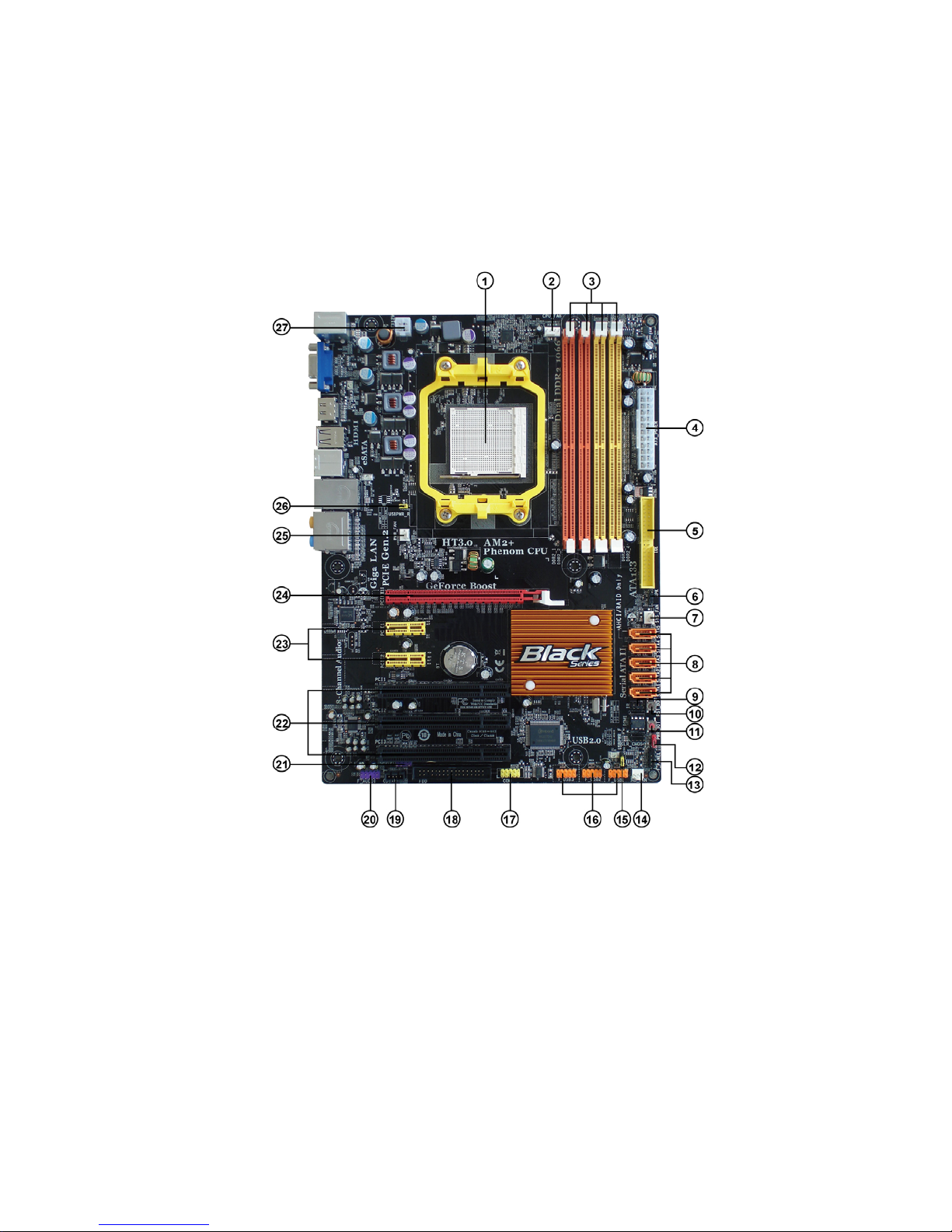
MotherboardComponents
6
IntroducingtheMotherboard
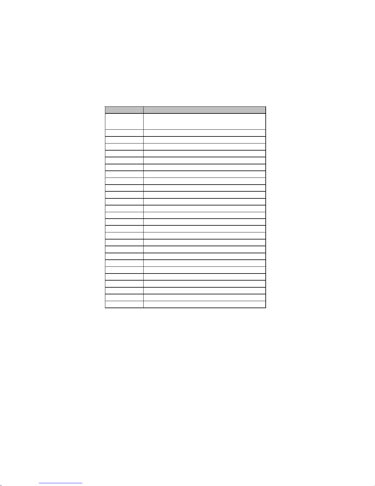
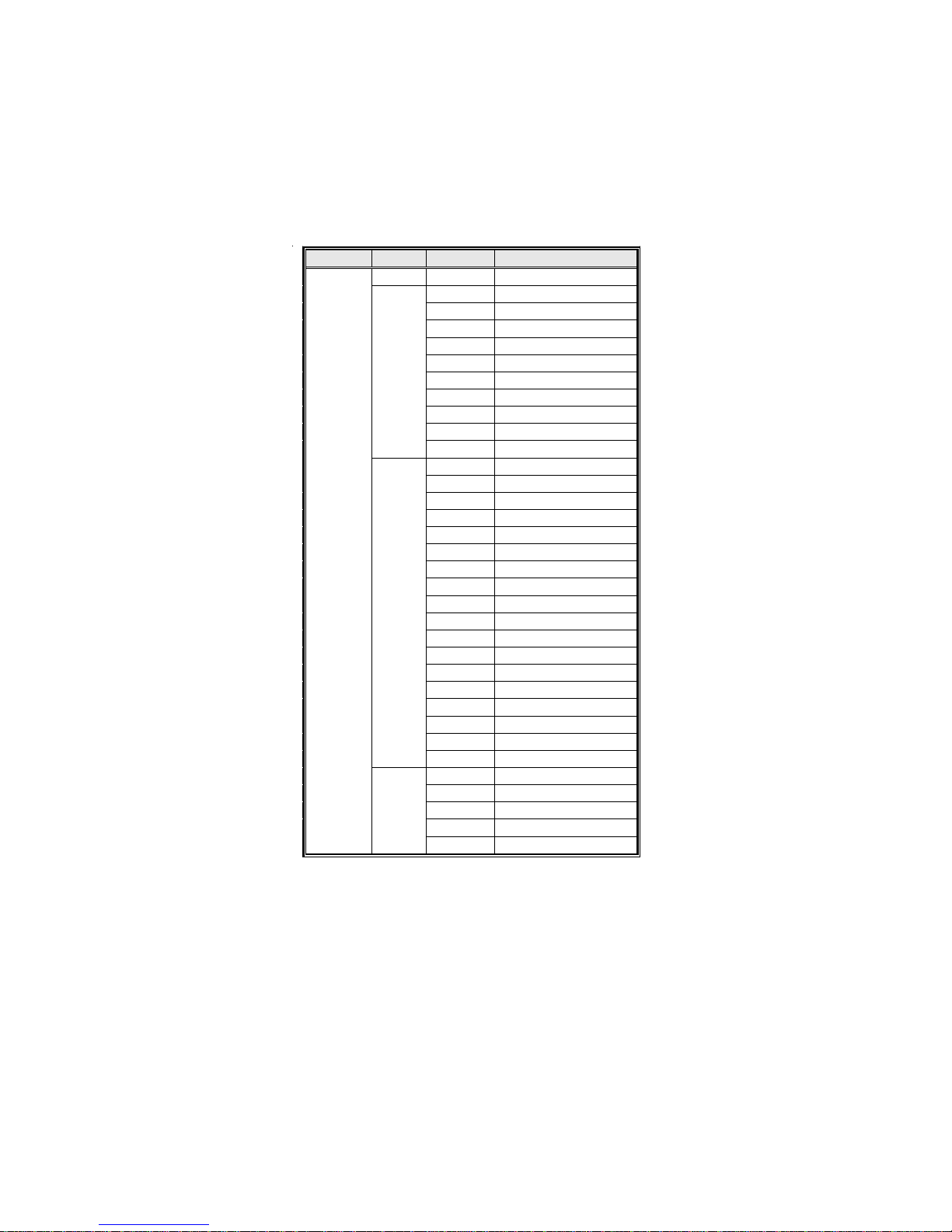
Table of Motherboard Components
This concludes Chapter 1. The next chapter explains how to install the motherboard.
LABEL COMPONENTS
1. CPU Socket Socket for AMD PhenomTM processor (socket AM2+)/AMD
AthlonTM 64 X2 Dual-Core/AthlonTM 64/SempronTM processors
2. CPU_FAN CPU cooling fan connector
3. DDR2_1~4 240-pin DDR2 SDRAM slots
4. ATX_POWER Standard 24-Pin ATX Power connector
5. IDE Primary IDE connector
6. SPK Internal speaker header
7. SYS_FAN System cooling fan connector
8. SATA1~5 Serial ATA connectors
9. IR Infrared header
10. RST_BOT Reset button
11. PWR_BOT Power on button
12. CLR_CMOS Clear CMOS jumper
13. F_PANEL Front Panel Switch/LED header
14. NB_FAN Northbridge coolingfan connector
15. USBPWR_F Front Panel USB Power Select jumper
16. F_USB1~3 Front Panel USB headers
17. COM OnboardSerial port header
18. FDD Floppy disk drive connector
19. CD_IN Analog Audio Input connector
20. F_AUDIO Front Panel Audio header
21. SPDIFO SPDIF out header
22. PCI1~3 32-bit add-on card slots
23. PCIE1~2 PCI Express x1 slots
24. PCIEX16 PCI Express x16 graphics cardslot
25. PWR_FAN Power cooling fan connector
26. USBPWR_R Rear USB/PS2 Power Select jumper
27. ATX12V 4-pin +12Vpower connector

7
InstallingtheMotherboard
Chapter2
InstallingtheMotherboard
SafetyPrecautions
• Follow these safety precautions when installing the motherboard
• Wear a grounding strap attached to a grounded device to avoid dam-
age from static electricity
• Discharge static electricity by touching the metal case of a safely
grounded object before working on the motherboard
• Leave components in the static-proof bags they came in
• Hold all circuit boards by the edges. Do not bend circuit boards
ChoosingaComputer Case
There are many types of computer cases on the market. The motherboard complies
with the specifications for the ATX system case. Firstly, some features on the
motherboard are implemented by cabling connectors on the motherboard to indica-
tors and switches on the system case. Make sure that your case supports all the
features required. Secondly, this motherboard supports one floppy diskette drive and
two enhanced IDE drives. Make sure that your case has sufficient power and space for
all drives that you intend to install.
Most cases have a choice of I/O templates in the rear panel. Make sure that the I/O
template in the case matches the I/O ports installed on the rear edge of the
motherboard.
This motherboard carries an ATX form factor of 305 x 220 mm. Choose a case that
accommodates this form factor.
Installingthe Motherboard ina Case
Refer to the following illustration and instructions for installing the motherboard in
a case.
Most system cases have mounting brackets installed in the case, which correspond
the holes in the motherboard. Place the motherboard over the mounting brackets
and secure the motherboard onto the mounting brackets with screws.
Ensure that your case has an I/O template that supports the I/O ports and expansion
slots on your motherboard.

8
InstallingtheMotherboard
CheckingJumperSettings
This section explains how to set jumpers for correct configuration of the motherboard.
SettingJumpers
Use the motherboard jumpers to set system configuration options. Jumpers with
more than one pin are numbered. When setting the jumpers, ensure that the jumper
caps are placed on the correct pins.
The illustrations show a 2-pin jumper. When
the jumper cap is placed on both pins, the
jumper is SHORT. If you remove the jumper
cap, or place the jumper cap on just one pin,
the jumper is OPEN.
This illustration shows a 3-pin jumper. Pins
1 and 2 are SHORT
SHORT OPEN
Do not over-tighten the screws as this can stress the motherboard.
9
InstallingtheMotherboard
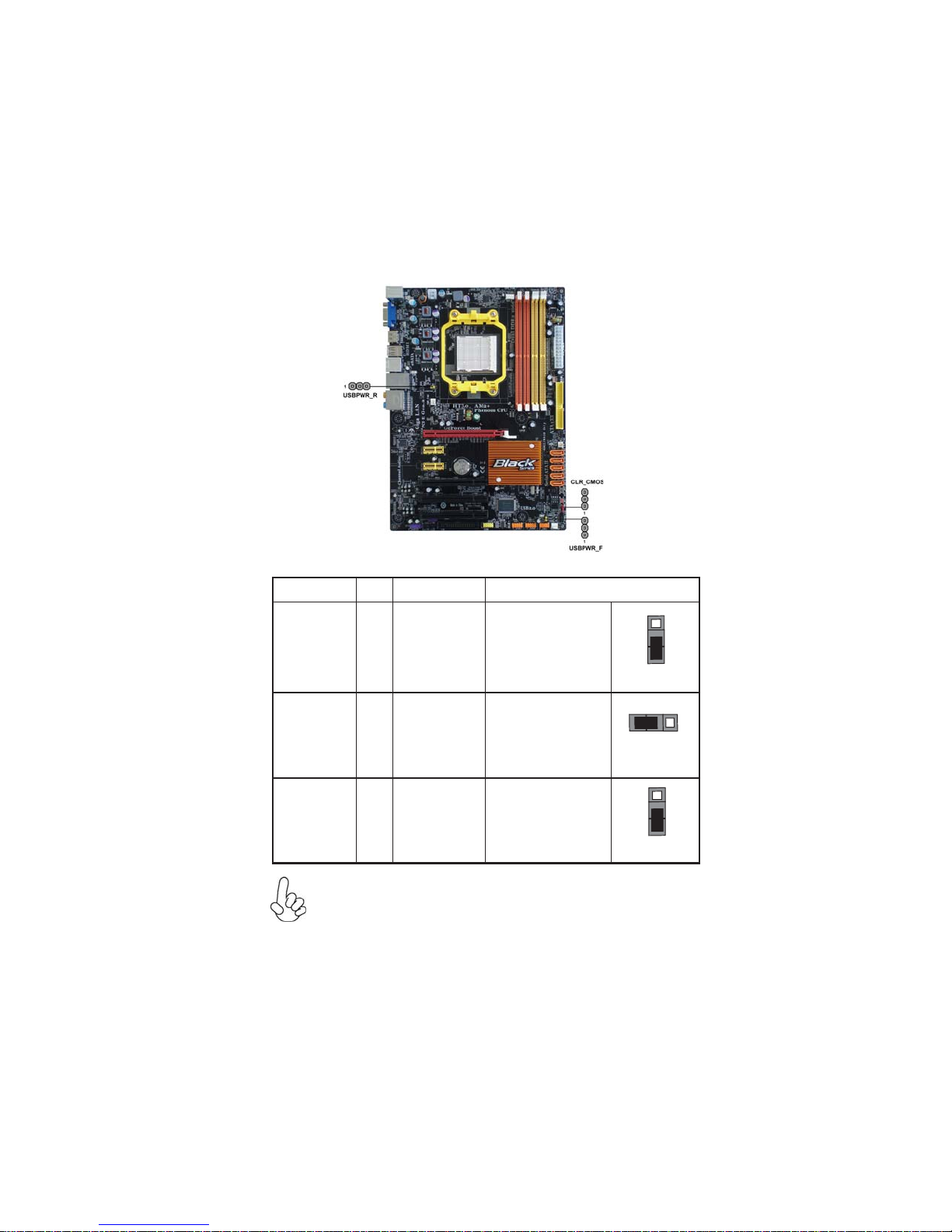
Checking Jumper Settings
The following illustration shows the location of the motherboard jumpers. Pin 1 is
labeled.
JumperSettings
To avoid the system instability after clearing CMOS, we recommend
users to enter the main BIOS setting page to “Load Optimized Defaults”
and then “Save & Exit Setup”.
1.
2. Make sure the power supply provides enough VCC5_DUAL voltage
before selecting the VCC5_DUAL function.
3. It is required that users place the USBPWR_F & USBPWR_R cap onto
2-3 pin rather than 1-2 pin as default if you want to wake up the
computer by USB/PS2 KB/Mouse.
Jumper Type Description Setting (default)
CLR_CMOS 3-pin CLEAR CMOS
1-2: NORMAL
2-3: CLEAR
Before clearing the
CMOS, make sure to
turn the system off.
3-pin
USBPWR_R 1-2: VCC5
2-3: VCC5_DUAL
Rear USB/PS2
Power Select
Jumper
3-pin
USBPWR_F 1-2: VCC5
2-3: VCC5_DUAL
Front Panel
USB Power
Select Jumper USBPWR_F
CLR_CMOS
1
1
USBPWR_R
1

10
InstallingtheMotherboard
InstallingHardware
Installing the Processor
Caution: When installing a CPU heatsink and cooling fan make sure that
you DO NOT scratch the motherboard or any of the surface-mount resis-
tors with the clip of the cooling fan. If the clip of the cooling fan scrapes
across the motherboard, you may cause serious damage to the motherboard
or its components.
This motherboard has a socket AM2+/AM2 processor socket. When choosing a
processor, consider the performance requirements of the system. Performance is
based on the processor design, the clock speed and system bus frequency of the
processor, and the quantity of internal cache memory and external cache memory.
Warning:
1. Over-clocking components can adversely affect the reliability of the
system and introduce errors into your system. Over-clocking can perma-
nently damage the motherboard by generating excess heat in components
that are run beyond the rated limits.
2. Always remove the AC power by unplugging the power cord from the
power outlet before installing or removing the motherboard or other
hardware components.
Before installing the Processor
This motherboard automatically determines the CPU clock frequency and system
bus frequency for the processor. You may be able to change these settings by making
changes to jumpers on the motherboard, or changing the settings in the system Setup
Utility. We strongly recommend that you do not over-clock processors or other
components to run faster than their rated speed.
On most motherboards, there are small surface-mount resistors near the
processor socket, which may be damaged if the cooling fan is carelessly
installed.
Avoid using cooling fans with sharp edges on the fan casing and the clips.
Also, install the cooling fan in a well-lit work area so that you can clearly
see the motherboard and processor socket.

11
InstallingtheMotherboard
CPU Installation Procedure
The following illustration shows CPU installation components.
To achieve better airflow rates and heat dissipation, we suggest that you
use a high quality fan with 4800 rpm at least. CPU fan and heatsink
installation procedures may vary with the type of CPU fan/heatsink sup-
plied. The form and size of fan/heatsink may also vary.
1 Unhookthe locking lever of theCPU socket. Pullthe
locking lever away from the socket and raising it to
the upright position.
2 Match the pin1 corner marked as the beveled edge
on the CPU with the pin1 corner on the socket.
Insert the CPU into the socket. Do not use force.
3 Push the locking lever down and hook it under the
latch on the edge of socket.
4 Apply thermal grease to the top of the CPU.
5 Install the cooling fan/heatsink unit onto the CPU,
and secure them all onto the socket base.
6 Plug the CPU fan power cable into the CPU fan
connector (CPU_FAN) on the motherboard.
Installing Memory Modules
This motherboard accommodates four memory modules. It can support four 240-pin
DDR2 1066 (AM2+)/800/667/533/400. The total memory capacity is 32 GB*.
DDR2 SDRAM memory module table
Do not remove any memory module from its antistatic packaging until
you are ready to install it on the motherboard. Handle the modules only
by their edges. Do not touch the components or metal parts. Always
wear a grounding strap when you handle the modules.
You must install at least one module in any of the four slots. Each module can be
installed with 8 GB of memory; total memory capacity is 32 GB*.
Memory module Memory Bus
DDR2 400 200 MHz
DDR2 533 266 MHz
DDR2 667 333 MHz
DDR2 800 400 MHz
DDR2 1066 533 MHz
12
InstallingtheMotherboard
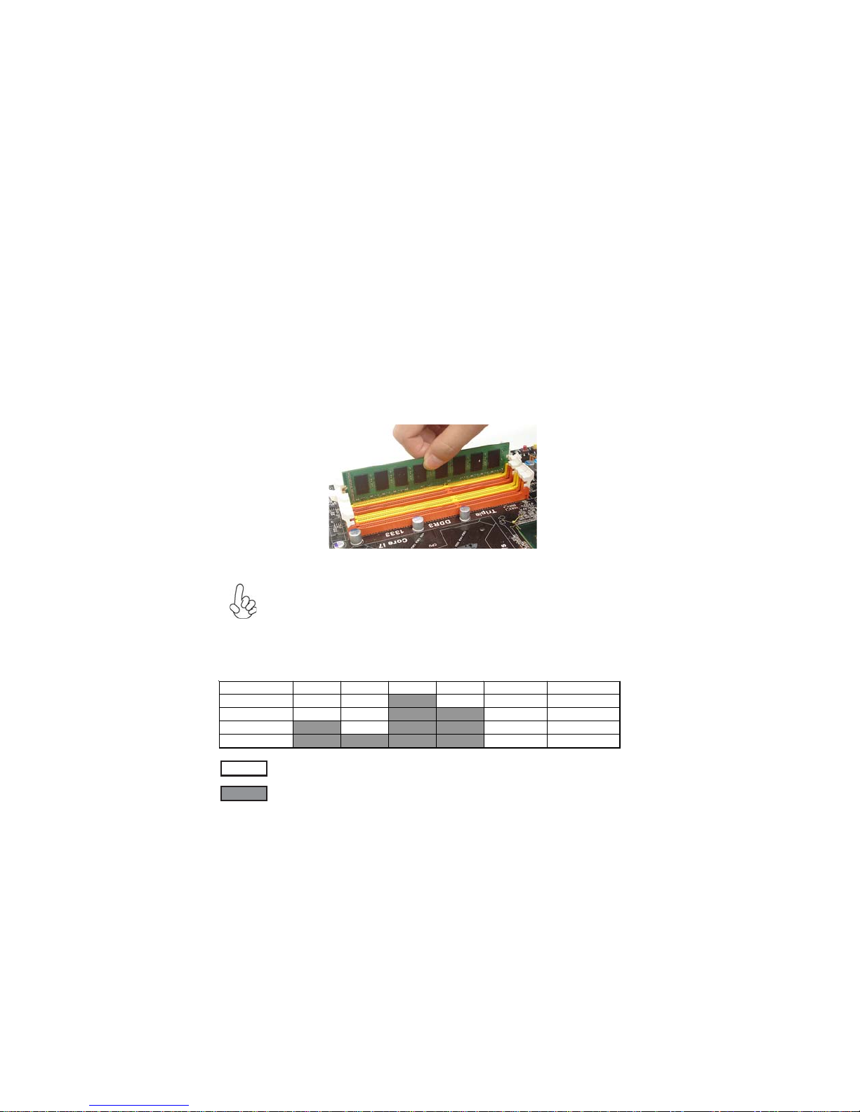
Installation Procedure
Refer to the following to install the memory modules.
1 This motherboard supports unbuffered DDR2 SDRAM only.
2 Push the latches on each side of the DIMM slot down.
3 Align the memory module with the slot. The DIMM slots are keyed with
notches and the DIMMs are keyed with cutouts so that they can only be
installed correctly.
4 Check that the cutouts on the DIMM module edge connector match the
notches in the DIMM slot.
5 Install the DIMM module into the slot and press it firmly down until it
seats correctly. The slot latches are levered upwards and latch on to
the edges of the DIMM.
6 Installany remaining DIMM modules.
For best performance and compatibility, we recommend that users
install DIMMs in the sequence of DIMM3, DIMM4, DIMM1 and
DIMM2.
Recommend configuration for best performance and compatibility
Number of DIMMs DIMM 1 DIMM 2 DIMM 3 DIMM 4 AM2 AM2+ *
1Single Channel Unganged Mode
2Dual Channel Ganged Mode
3Single Channel Unganged Mode
4Dual Channel Ganged Mode
: operation with normal performance
: operation with the best performance
13
InstallingtheMotherboard
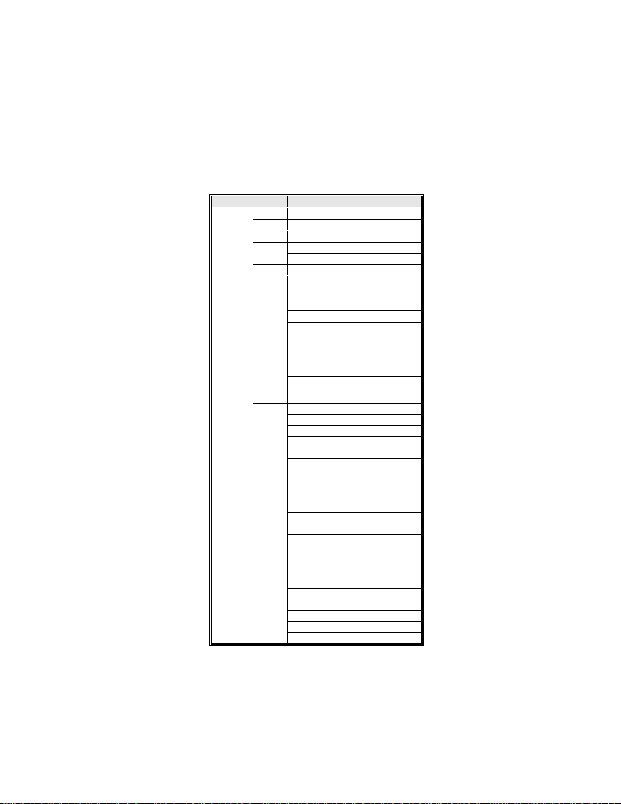
Table A: DDR2(memory module) QVL (Qualified Vendor List)
The following DDR2 1066 (AM2+)/800/667/533/400 memory modules have been
tested and qualified for use with this motherboard.
Type Size Vendor Module Name
256 MB Hynix HYMP532U646-E3 AA
DDR2 400 512 MB Nanya NT512T64U88A0F-5A
256 MB Elixir M2U25664TUH4A0F-37B
Aeneon AET660UD00-370A98Z
512 MB Infineon HYS64T64400HU-3.7-A
DDR2 533
1 GB Infineon HYS64T128920HU-3.7-A
256 MB Infineon HYS64T32400HU-3S-A
A-DATA M2OAD5G3H3166I1C52
Apacer 78.91G92.9K5
APOGEE AU51082-667P005
Cosair VS512MB667D2
Kingston KVR667D2N5/512
Micron MT4HTF6464AY-667E1
Nanya NT512T64U88A0BY-3C
PSC AL6E8E63J-6E1
Ramxel RML1520HC38D6F-667
512 MB
Transcend Transcend K4T51083QC
ZCE6
A-DATA M2OAD5G3I4176I1C52
Apacer 78.01G9O.9K5
APOGEE AU1G082-667P005
Hynix HYMP112U64CP8-Y5 AB
Kingston KVR667D2N5/1G
Micron MT8HTF12864AY-667E1
PSC AL7E8E63B-6E1T
PSC AL7E8E63J-6E1
PSC AL7E8F73C-6E1
Qimonda HYS64T128020HU-3S-B
Ramxel RML1320HC38D7F-667
Samsung M378T2863DZS-CE6 0743
1 GB
Twinmos 8D23KK-TT
Aeneon AET860UD00-30DC08S
Aeneon AET860UD00-30DB08X
Apacer 78.A1G9O.9K4
Hynix HYMP125U64AP8-Y5-AB-A
Kingston KVR667D2N5/2G
Nanya NT2GT64U8HB0JY-3C
PSC AL8E8F73C-6E1
Qimonda HYS64T256020EU-3S-C2
DDR2 667
2 GB
Twinmos 8D-23MK-ED
14
InstallingtheMotherboard
Type Size Vendor Module Name
256 MB Infineon HYS64T32000HU-25F-B
A-DATA M2OAD6G3H3160I1E53
Aeneon AET660UD00-25DB98X
APOGEE AU51082-800P505
Infineon HYS64T64000HU-25F-B
Infinity 04751208CZ5U2D
Kingston KHX6400D2ULK2/1G
Kingston KVR800D2N5/512
Micron MT8HTF6464AY-80ED4
Nanya NT512T64U88B0BY-25C
512 MB
PSC AL6E8E63H-8E1
Aeneon AET760UD00-25DC08X
Aeneon AET860UD00-25DC08X
Apacer 78.01GA0.9K5
APOGEE AU1G082-800P000
Infineon HYS64T128020HU-25F-B
Infinity 04701G16CZ5U2G
Kingston KHX6400D2ULK2/2G
Kingston KHX6400D2LLK2/2G
Kingston KHX6400D2LLK2/2GN
Kingston KHX6400D2K2/2G
Kingston KVR800D2N5/1G
Micron MT8HTF12864AY-80EE1
UMAX U2S12D30TP-8E
Nanya NT1GT64U8HB0BY-25C
NCP NCPT7AUDR-25M48
PSC AL7E8E63H-8E1
PSC AL7E8F73C-8E1
1 GB
UMAX 53016042-7100B
Apacer 78.A1GA0.9K4
Kingston KHX6400D2/2G
Micron MT16HTF25664AY-800E1
PSC AL8E8F73C-8E1
DDR2 800
2 GB
Qimonda HYS64T256020EU-25F-C2
Table of contents
Other ECS Motherboard manuals


