ECS APLD-I User manual

APLD-I USER MANUAL
The information in this document is subject to change without notice. The
manufacturer makes no representations or warranties with respect to the contents
hereof and specifically disclaims any implied warranties of merchantability or
fitness for any particular purpose. The manufacturer reserves the right to revise this
publication and to make changes from time to time in the content hereof without
obligation of the manufacturer to notify any person of such revision or changes.
This equipment has been tested and found to comply with the limits for a Class B
digital device, pursuant to Part 15 of the FCC Rules. These limits are designed to
provide reasonable protection against harmful interference in a residential
installation. This equipment generates, uses, and can radiate radio frequency
energy and, if not installed and used in accordance with the instructions, may cause
harmful interference to radio communications. However, there is no guarantee that
interference will not occur in a particular installation. If this equipment does cause
harmful interference to radio or television reception, which can be determined by
turning the equipment off and on, the user is encouraged to try to correct the
interference by one or more of the following measures:
•Reorient or relocate the receiving antenna
•Increase the separation between the equipment and the receiver
•Connect the equipment onto an outlet on a circuit different from that to
which the receiver is connected
•Consult the dealer or an experienced radio/TV technician for help
Shielded interconnect cables and a shielded AC power cable must be employed with
this equipment to ensure compliance with the pertinent RF emission limits
governing this device. Changes or modifications not expressly approved by the
system’s manufacturer could void the user’s authority to operate the equipment.
Federal Communications Commission (FCC)
Disclaimer
Declaration of Conformity
This device complies with part 15 of the FCC rules. Operation is subject to the follow-
ing conditions:
•This device may not cause harmful interference.
•This device must accept any interference received, including interference
that may cause undesired operation.
Electromagnetic compatibility of multimedia equipment - Emission
requirements
EN 55032
EN 61000-3-2 Electromagnetic Compatibility(EMC)
Part 3-2: Limits-Limits for harmonic current emissions (equipment input
current 16A per phase)
EN 61000-3-3 Electromagnetic Compatibility(EMC)
Part 3-3: Limits-Limitation of voltage changes, voltage fluctuations and flicker
in public low-voltage supply systems, for equipment with rated current 16A
per phase and not subject to conditional connection
EN 55024 Information technology equipment-Immunity characteristics-Limits and
methods of measurement
EN 60950 Safety for information technology equipment including electrical business
equipment
CE marking
This device is in conformity with the following EC/EMC directives:

ii
APLD-I USER MANUAL
TABLE OF CONTENTS
Preface i
Brief Introduction 1
Specifications......................................................................................1
Motherboard Components................................................................3
Header Pin Definition and Jumper Settings.........................................5
I/O Ports...............................................................................................8
Multi-language Quick Installation Guide 9
English...................................................................................................9
Simplified Chinese...............................................................................11
Korean......................................................................................................13
Indonesian.............................................................................................15
Japanese................................................................................................17
Vietnamese..........................................................................................19
APLD-I USER MANUAL
1
Brief Introduction
Specifications
SoC
• Single channel DDR3L SO-DIMM memory architecture
• 1 x 204-pin DDR3L SO-DIMM socket supports up to 8 GB
• Supports DDR3L 1600 MHz SDRAM
Memory
• 1 x M.2 slot(Socket 3 key M 2242/2260/2280 for SATA SSD)
(It shares the same signal with SATA2)
• Supported by Intel® Apollo Lake 1296 BGA
- 2 x Serial ATA 6Gb/s devices
Expansion
Slots
Storage
Rear Panel I/O
LAN • Realtek RTL8111H Gigabit LAN
• Realtek ALC662-VD0-GR 6CH HD Audio CODEC
• Realtek ALC105VF 4ohm 3w Amplifier (optional)
- 6 Channel High Definition Audio Codec
- Compliant with HD audio specification
Audio
• Onboard Intel® Apollo Lake 1296 BGA
• 1 x 24-pin ATX Power Supply connector*(or DC_IN port at rear
panel)
• 1 x 4-pin SYS_FAN connector
• 2 x USB 2.0 headers support additional four USB 2.0 ports
• 1 x USB 3.0 header supports additional two USB 3.0 ports
• 2 x Serial ATA 6Gb/s connectors(SATA2 shares the same signal
with M.2 slot)
• 1 x Buzzer
• 1 x Front Panel switch/LED header
• 1 x Front Panel audio header
• 1 x Clear CMOS jumper
• 1 x MONO jumper
• 2 x COM headers
• 1 x Case open header
• 1 x SATA power connector
• 1 x Debug card header
• 1 x Printer header
• 1 x Amplifier Speaker header
Internal I/O
Connectors &
Headers
Note: Please go to our website for the latest CPU support list.
Note: Please go to our website for the latest Memory support list.
• 1 x DC_IN port*(or internal ATX_POWER header)
• 1 x PS/2 Keyboard & PS/2 Mouse connectors
• 1 x D-sub (VGA) port*(or DP port)
• 1 x HDMI port
• 2 x USB 3.0 ports
• 1 x RJ45 LAN connector
• 2 x USB 2.0 ports
• 1 x Audio port (1 x line-in, 1 x line-out, 1 x Microphone)
Note: *VGA port(real panel I/O) + DC_IN port(real panel I/O) and DP port
(real panel I/O) + ATX_POWER header(internal I/O header) are alternative
options of the motherboard.

APLD-I USER MANUAL
2
QR Code for the complete manual download
on ECS website: http://www.ecs.com.tw
System BIOS
Form Factor • Mini ITX Size, 170mm x 170mm
• AMI BIOS with 128Mb SPI Flash ROM
- Supports recovery
- Supports Dual/Triple Display
- Supports Plug and Play
- Supports ACPI & DMI
- Supports STR (S3) /STD (S4)
- Supports Hardware monitor
- Support PgUp clear CMOS Hotkey (PS2 KB Model only)
- Audio(Buzzer), LAN, can be disabled in BIOS
- F7 hot key for boot up devices option
- Add BIOS parameters and copy to USB Flash Drive
APLD-I USER MANUAL
3
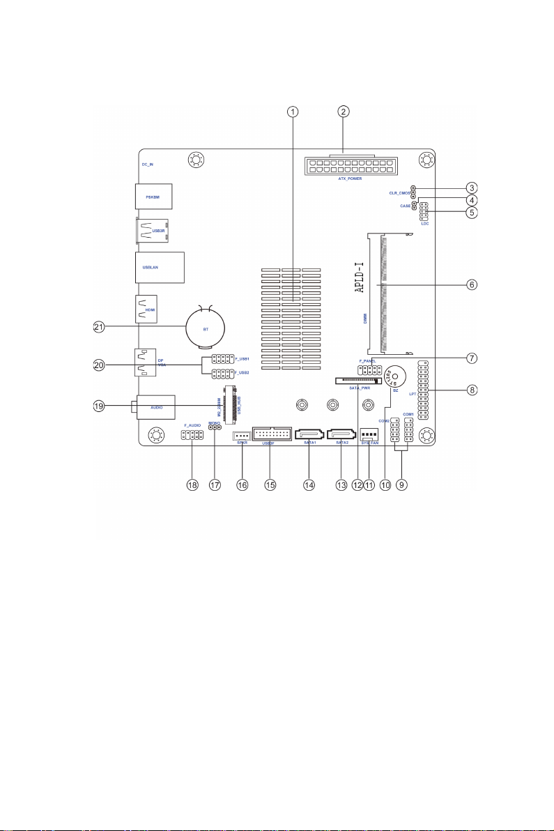
Motherboard Components
APLD-I USER MANUAL
4
Table of Motherboard Components
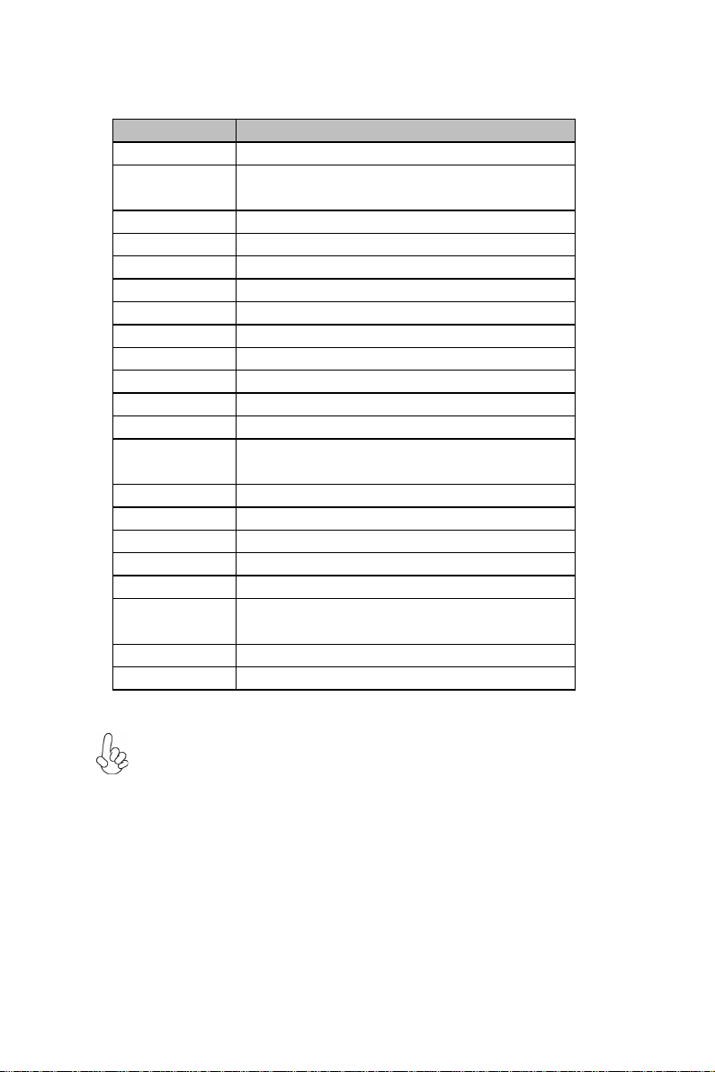
LABEL
COMPONENTS
1. SoC
Intel® Apollo Lake 1296 BGA
2. ATX_PWR Standard 24-pin ATX power connector*(or
DC_IN port at rear panel)
3. CLR_CMOS
Clear CMOS jumper
4. CASE
Case open header
5. LDC Debug card header
6. DIMM
204-pin DDR3L SDRAM SO-DIMM
7. F_PANEL
Front panel switch/LED header
8. LPT Onboard parallel port header
9. COM1~2 Onboard serial port headers
10. BZ
Buzzer
11. SYS_FAN
4-pin system cooling fan connector
12. SATA_PWR
SATA power connector
13. SATA2 Serial ATA 6Gb/s connector (shares the same
signal with M.2 slot)
14. SATA1
Serial ATA 6Gb/s connector
15. USB3F
Front panel USB 3.0 header
16. SPKR
Amplifier speaker header
17. MONO
MONO jumper
18. F_AUDIO
Front panel audio header
19. M2_2280M M.2 slot for 2242/2260/2280 SATA SSD (shares
the same signal with SATA2)
20. F_USB1~2
Front panel USB 2.0 headers
21. BT
Battery
Note: *VGA port(real panel I/O) + DC_IN port(real panel I/O) and DP port
(real panel I/O) + ATX_POWER header(internal I/O header) are alternative
options of the motherboard.
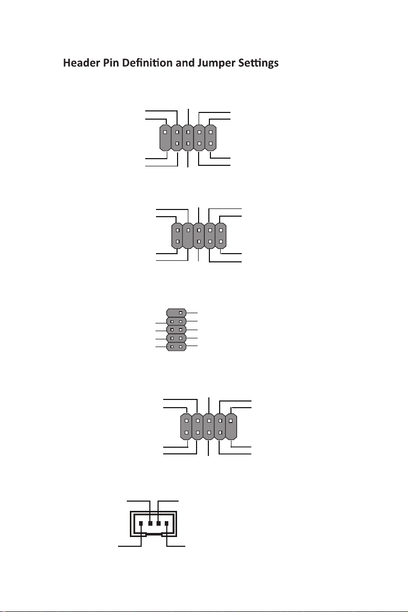
APLD-I USER MANUAL
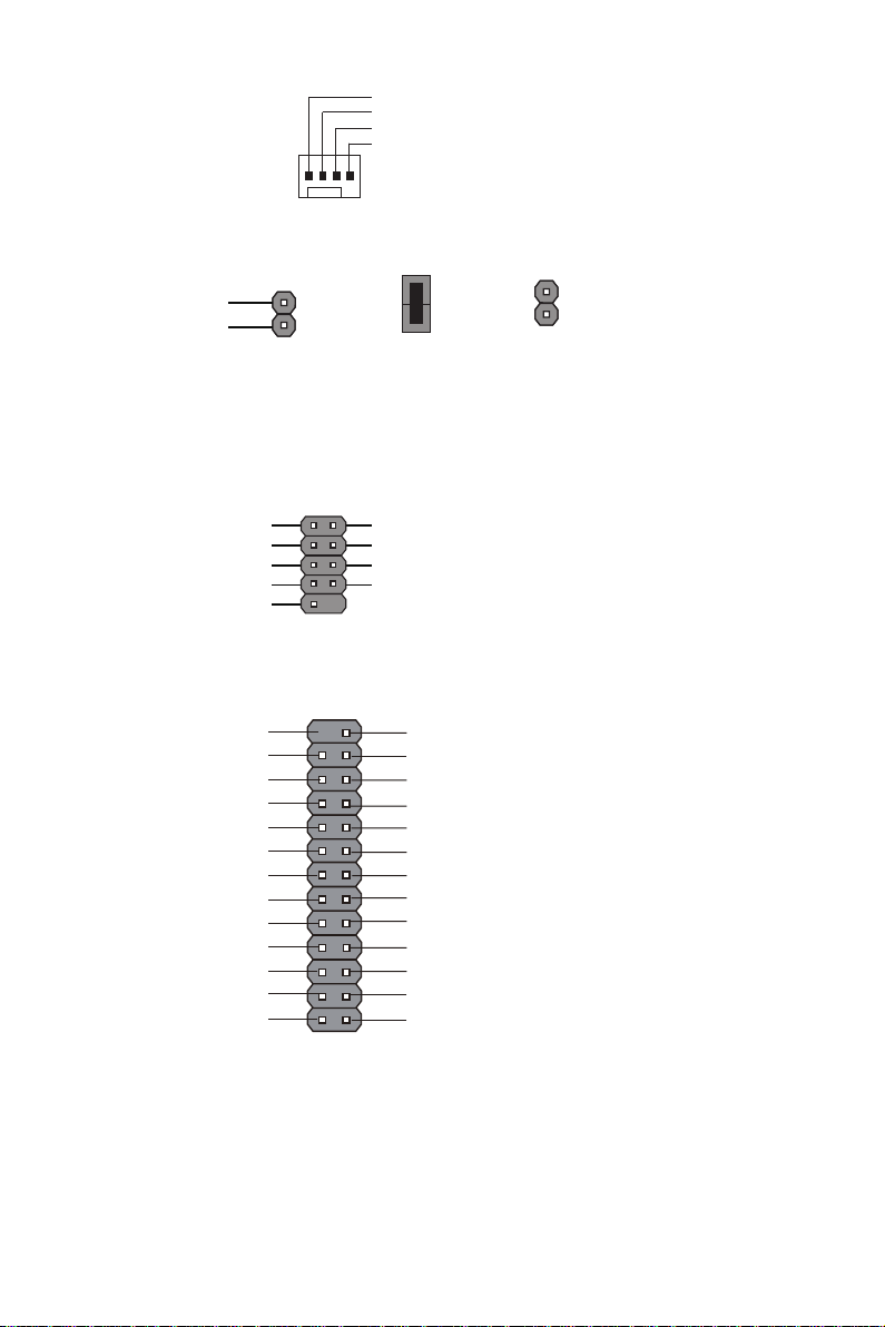
F_AUDIO
F_USB1~2
COM1~2
F_PANEL
1
Serial Output
Data Carrier Detect
Serial Input
Ring Indicator
Data Terminal Ready
Clear to Send Request to Send
Data Set Ready Ground
SPKR
1
VCCSignal
Key
GND
1
9
NC
KEY
Ground
Power +5V
Power +5V
GroundUSB Port A (-)
USB Port B (-)
USB Port A (+)
USB Port B (+)
1
PORT 1L
PORT 1R
PORT 2R
AUD_GND
AUD_GND
PRESENCE#
SENSE1_RETURN
Key
SENSE2_RETURN
PORT 2L
KEY
1
Hard disk LED (-)
Hard disk LED (+)
Reset Switch (-)
Reset Switch (+)
Reserved
Power Switch (-) Power Switch (+)
MSG LED (+)
MSG LED (-)
6
APLD-I USER MANUAL
CASE
Chassis cover
is removed
Chassis cover
is closed
2
11
SYS_FAN
Sensor
PWM
System Ground
Power +12V
1
LDC
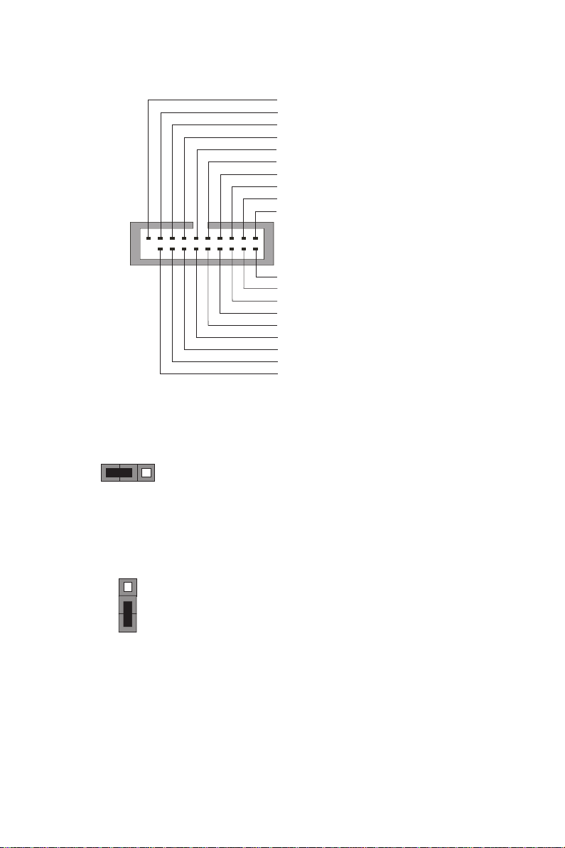
LPT
1
INIT
Ground
SLCT
Ground
Key
Ground
Ground
AFD
ERROR
Ground
Ground
Ground
Ground
PD1
PD5
PD2
PD6
SLCT
PD4
PD3
STROBE
PD0
PD7
ACK
BUSK
PE
1
Intruder
GND
LPC Signal
LPC Signal
LPC Signal
LPC Signal
LPC signal
Ground
Reset
Clock
Power +3.3V
1
7
APLD-I USER MANUAL
CLR_CMOS Jumper
1-2: NORMAL
Before clearing the CMOS, make sure to turn off the system.
CLR_CMOS
3 12
2-3: CLEAR CMOS
MONO Jumper
1-2: Stereo
MONO
3
1
2
2-3: Mono
1
Front Panel USB Power
Front Panel USB Power
Ground
Ground
USB3 ICC Port1 D+
Not Connected
Ground
Ground
USB3 ICC Port1 D-
USB3 ICC Port2 D+
USB3 ICC Port2 D-
USB3 ICC Port1 SuperSpeed Rx-
USB3 ICC Port2 SuperSpeed Rx-
USB3 ICC Port1 SuperSpeed Rx+
USB3 ICC Port2 SuperSpeed Rx+
USB3 ICC Port1 SuperSpeed Tx-
USB3 ICC Port2 SuperSpeed Tx-
USB3 ICC Port1 SuperSpeed Tx+
USB3 ICC Port2 SuperSpeed Tx+
USB3F

APLD-I USER MANUAL
8
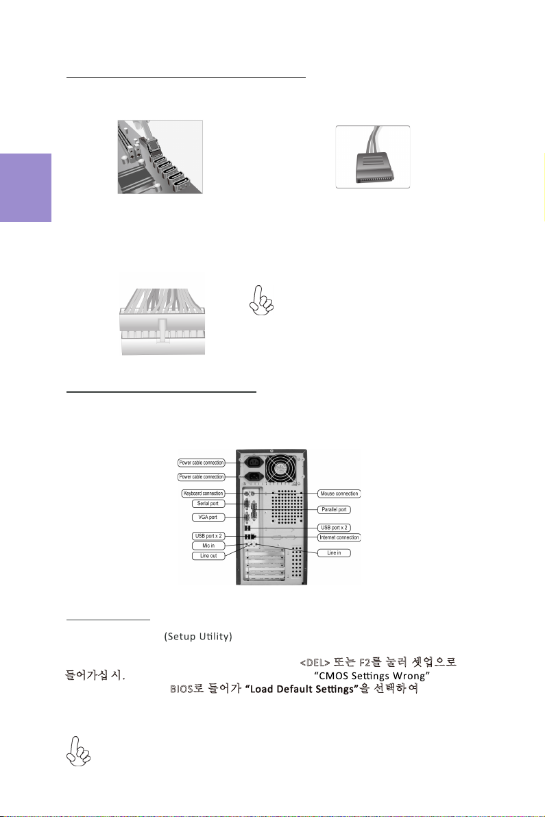
I/O Ports
1. PS/2 Mouse (green)
Use the upper PS/2 port to connect a PS/2 mouse.
2. PS/2 Keyboard (purple)
Use the lower PS/2 port to connect a PS/2 keyboard.
3. USB 3.0 Ports
Use the USB 3.0 port to connect USB 3.0 device.
4. USB 2.0 Ports
Use the USB 2.0 ports to connect USB 2.0 devices.
5. LAN Port
Connect an RJ-45 jack to the LAN port to connect your computer to the Network.
6. HDMI Port
You can connect the display device to the HDMI port.
7. DP Port*(optional)
You can connect the display device to the display port.
8. Line-in (blue)
It can be connected to an external CD/DVD player, Tape player or other audio
devices for audio input.
9. Line-out (green)
It is used to connect to speakers or headphones.
10. Microphone (pink)
It is used to connect to a microphone.
11. DC_IN Port* (optional)
Connect the DC_IN port to the power adapter.
12. VGA Port*(optional)
Connect your monitor to the VGA port.
Link LED
LAN Port
Note: *VGA port(real panel I/O) + DC_IN port(real panel I/O) and DP port
(real panel I/O) + ATX_POWER header(internal I/O header) are alternative
options of the motherboard.
LAN LED
Status
Description
OFF
No data
Orange blinking
Active
OFF
No link
Green
Link (10/100 port)
Orange
Link (Giga port)
Activity LED
Link LED
or

9
English
Hardware Installation Guide
Installation Steps
Step 3. Installation of an Expansion card:
Remove the metal located on the slot and then insert the expansion card into the
slot. Press the card firmly to make sure it is fully inserted into its slot. And then
return the screw back to its position.
Step 1. Installation of Memory Modules:
1-1. Align the cutouts on the DIMM
module edge connector to the notches
in the DIMM slot.
Step 2. Installation of Motherboard:
2-1. Replace the back I/O plate of the
case with the I/O shield provided in
motherboard’s package.
1-2. Insert the memory module to the
slot and press it down until it seats
correctly. Make sure the slot latches
cling to the edge of the DIMM module.
2-2. Place the motherboard within the
case by positioning it into the I/O plate.
Secure the motherboard to the case
with screws.
VGA port(real panel I/O) + DC_IN port(real panel I/O) and DP port (real panel
I/O) + ATX_POWER header(internal I/O header) are alternative options of
the motherboard.

10
English
Step 4. Connecting Cables and Power Connectors:
c. Connect 24-pin power cable
b. Connect SATA power connector to the
SATA device
Once the steps above have been completed, please connect the peripherals such
as the keyboard, mouse, monitor, etc. Then, connect the power and turn on the
system. Please install all the required software.
Step 5: Connecting ports on the case:
a. Connect the SATA hard drive to its
SATA cable
Please note that when installing 24-pin
power cable, the latches of power cable
and the ATX connector match perfectly.
The sequence of installation may differ depending on the type of case and
devices used.
Using BIOS
The BIOS (Basic Input and Output System) Setup Utility displays the system’s
configuration status and provides you options to set system parameters. When
you power on the system, BIOS enters the Power-On Self Test (POST) routines,
please press <DEL> or F2 to enter setup. When powering on for the first time, the
POST screen may show a “CMOS Settings Wrong” message. Please enter BIOS and
choose “Load Default Settings” to reset the default CMOS values. (Changes to
system hardware such as different CPU, memories, etc. may also trigger this
message.)
VGA port(real panel I/O) + DC_IN
port(real panel I/O) and DP port (real
panel I/O) + ATX_POWER header(internal
I/O header) are alternative options of the
motherboard.

11
硬件安装指南
安装步骤
1.安装记忆体模组:
1-1. 将DIMM模块边缘连接器上的切口
与DIMM插槽中的凹槽对齐。
2.
2-1. 取下机箱后面的I/O挡板,换上主
板附带的I/O弹片。
1-2. 将内存模块插入插槽和向下按直至
其正确就位。 确保插槽锁扣紧贴DIMM
模块的边缘。
2-2. 将主板的后I/O对准机箱上的I/O挡板孔
位,放入机箱并以螺丝固定。
3.
移除机箱后面的扩充金属挡板,确认扩充卡完全插入扩展 槽后,重新拧上螺丝。
简体中文
VGA端口(实际面板I / O)+ DC_IN端口(实际面板I / O)和DP端口(实际
面板I / O)+ ATX_POWER头(内部I / O头)是可选的选项的主板。

12
4.连接电源线与电源接头:
c. 连接24针电源线与电源接头
b. 将SATA电源接头连接至SATA设备a. 将SATA电缆连接至SATA 硬盘
请注意电源接头与电源线必须完全扣合
简体中文
当上述安装步骤完成后,请开始安装键盘,鼠标,
源并启
显示器等外围设备,然后连接电
动系统。请安装好所需的软件。
5.连接机箱端口:
此说明内容中提供图片或安装方式仅供参考。
BIOS使用设定
BIOS程序画面会显示系统配置,同时提供操作选项让您设定系统参数。当开机时,
BIOS会进行开机自我测试 (POST),请点击<D EL> 或F2 进入BIOS程序设定。第一次
开机时,POST画面可能会显示 信息,请进入BIOS选单并选
择将BIOS重新设定为默认值 (更换CPU或内存等硬件变更也
可能会出现此信息)。
VGA端口(实际面板I / O)+ DC_IN端
口(实际面板I / O)和DP端口(实际
面板I / O)+ ATX_POWER头(内部I / O
头)是可选的选项的主板。

13
모듈 설치하기:
하드웨어 설치 가이드
단계별 설치 방법
1단계. 메모리
1-1. DIMM 모듈 에지 커넥터의 컷아웃을
DIMM 슬롯의 노치에 맞춥니 다.
2단계. 마더보드 설치하기:
2-1. 케이스 의 후 면 I / O 플레이트를
마더보드의 패키지 에 제 공 된 I / O
실드로 교체합니다.
1-2. 메모리 모듈을 슬롯에 삽입하고 올바르게
장착 될때까지 아래로 누르십시오. 슬롯
래치가 DIMM 모듈의 모서리에 달라 붙지
않도록하십시오.
2-2. 마더보드를 I / O 플레이트에
위치시
켜케이스 내 에.
스크류 로
마더보드를
케이스 에 고정시킵니다.
한국어
3단계. 확장 카드 설치하기:
슬롯에설치되어 있는 금속을제거하고 확장 카드를해당 슬롯에삽입합니다. 슬롯에
완전히삽입될수있도록카드를단단히누릅니다. 스크류를 다시 제자리에체결합니다.
VGA 포트 (실제 패널 I / O) + DC_IN 포트 (실제 패널 I / O) 및 DP 포트
(실제 패널 I / O) + ATX_POWER 헤더 (내부 I / O 헤더)는 선택 사항입니다
마더 보드의 옵션.
14
4단계. 케이블및전원 커넥터연결하기:
c. 2 4핀전원 케이블을 연결합니다
b. SATA 전원 커넥터를 SATA 장치에연결합
니다
a. SATA 하드 드라이브를 SATA
케이블에 연결합니다
24핀전원 케이블연결시전원 케이블과
ATX 커넥터의 걸쇠가완벽하게 맞아야
합니다.
한국어
일단 위의 단계들이 완료되면, 키보드, 마우스, 모니터 등과 같은 주변기기들을
연결
합니다. 그런 후에, 전원을 연결하고 시스템을 켭니다. 모든 필수 소프트웨어를 설치
합니다.
5단계. 케이스의 포트 연결하기:
BIOS 사용하기
BIOS 셋업 유틸리티 는 시스템의 환경설정 상태를 표시하며 시스템
매개변수를 설정하기 위한 옵션을 제공합니다. 시스템의 전원을 켜면, BIOS는
Power-On Self Test (POST) 루틴을 실행합니다, <DEL> 또는 F2를눌러 셋업으로
들어가십 시.오 처음으로 전원을 켜면 POST 화면에 메시지가
나타날 수 있습니다. BIOS로들어가 을선택하 여 기본 CMOS
설정값을 재설정합니다. (CPU, 메모리 등과 같은 시스템 변경할 때에도 본 메뉴가
나타날 수있습니다.)
설치절차는 사용된 케이스 및장치의 유형에 따라 다를 수있습니다.
VGA 포트 (실제 패널 I / O) + DC_IN
포트 (실제 패널 I / O) 및 DP 포트
(실제 패널 I / O) + ATX_POWER 헤더
(내부 I / O 헤더)는 선택 사항입니다
마더 보드의 옵션.
15
Panduan Pemasangan Perangkat Keras
Langkah-Langkah Pemasangan
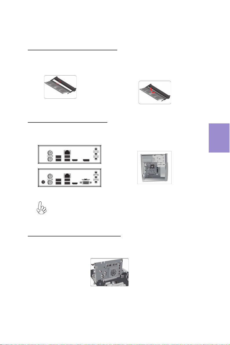
Langkah 1. Pemasangan Modul Memori:
1-1. Sejajarkan gunngan pada modul DIMM
konektor tepi ke takik di slot DIMM.
Langkah 2. Pemasangan Motherboard:
2-1. Pasang kembali pelatI/O casing
dengan pelindung I/O yang disediakan
dalampaketmotherboard.
1-2. Masukkan modul memori ke slot dan
tekan ke bawah sampai itu kursi dengan benar.
Paskan kait slot yang melekat pada tepi
modul DIMM.
2-2. Tempatkan motherboardpada casing
dengan memosisikannya ke dalampelatI/O.
Kencangkan motherboardpada casing
dengan
sekrup.
Bahasa
Indonesia
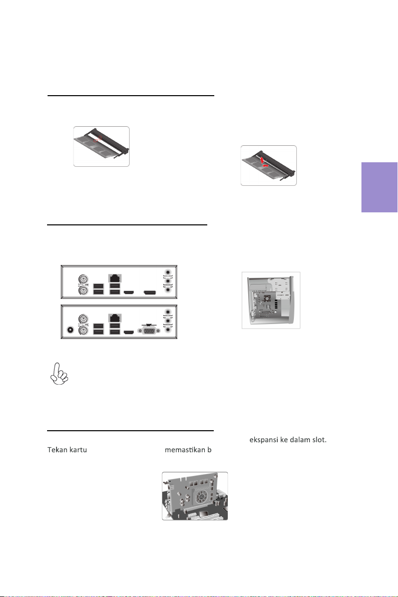
Langkah 3. Pemasangan kartu Ekspansi:
Lepaskan logamyang terletak pada slot lalu masukkan kartu
dengan kencang untuk ahwa kartu telah masuk sepenuhnya ke
dalamslot. Lalu pasang kembali sekrupke dalam posisinya.
Port VGA (panel aktual I / O) + pelabuhan DC_IN (panel aktual I / O) dan port DP
(Panel aktual I / O) + ATX_POWER header (internal yang I / O sundulan) adalah opsional
Pilihan pada motherboard.
16
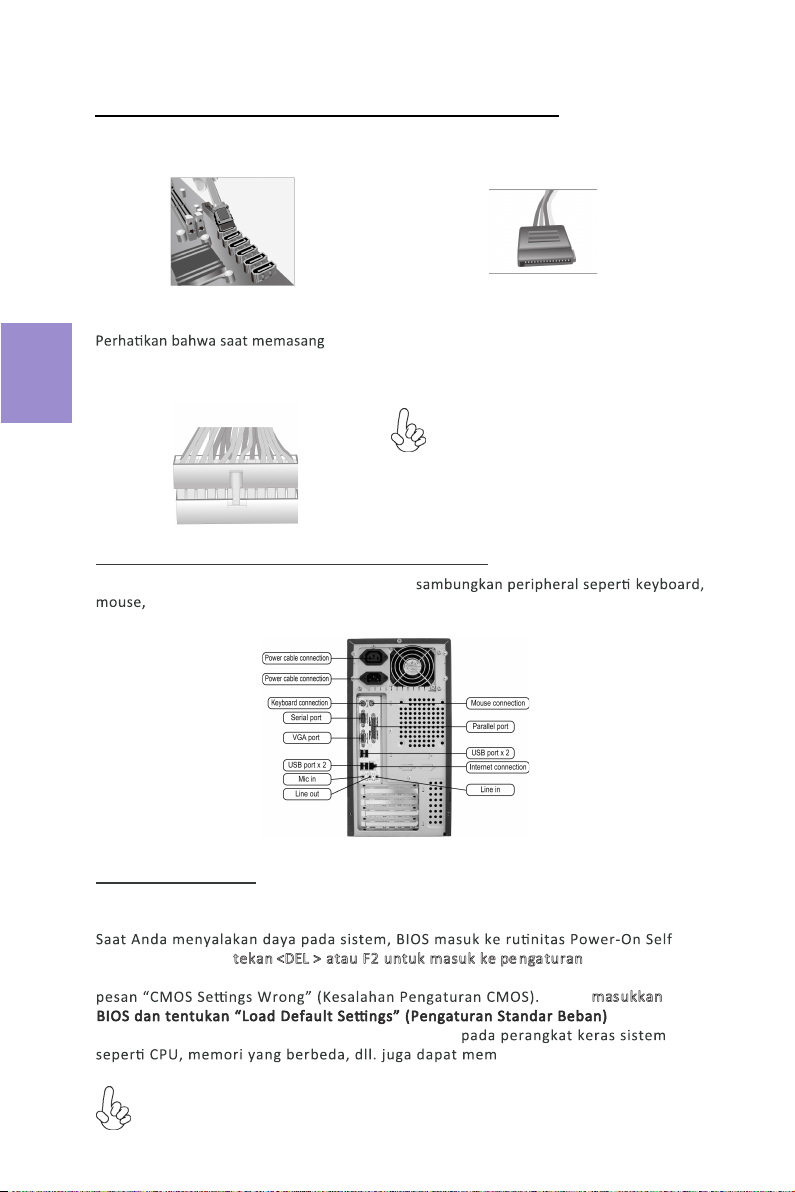
Langkah 4. Menyambungkan Kabel dan Konektor Daya:
c. Sambungkan kabel daya 24 pin
a. Sambungkan hard drive SATA ke kabel
SATA
b. Sambungkan konektor daya SATA ke
perangkat SATA
kabel daya 24, kait pada kabel daya
dan konektor ATX harus sesuai.
Bahasa
Indonesia
Setelah langkah-langkah di atas selesai, harap
monitor, dll. Lalu sambungkan daya dan nyalakan sistem. Harap pasang semua
perangkat lunak yang dibutuhkan.
Langkah 5. Menyambungkan port pada casing:
Menggunakan BIOS
Utulitas Pengaturan BIOS (Basic Input and Output System) menampilkan status
konfigurasi sistem dan memberi Anda opsi untuk mengatur parameter sistem.
Test (POST), harap tekan <DEL > atau F2 untuk masuk ke pe ngaturan. Saat
menyalakan untuk pertama kalinya, layar POST mungkin akan menunjukkan
untuk
icu pesan ini.)
Harap masukkan
menyetel kembali nilai CMOS standar. (Perubahan
Urutan pemasangan mungkin berbeda bergantung pada jenis casing dan
perangkat yang digunakan.
Port VGA (panel aktual I / O) +
pelabuhan DC_IN (panel aktual I / O)
dan port DP (Panel aktual I / O) +
ATX_POWER header (internal yang
I / O sundulan) adalah opsional
Pilihan pada motherboard.
17
ハードウェアインストールガイド
インストール手順
手順 1 メモリモジュールのインストール:
2-2. メモリモジュールをスロットに挿入し、それ
が正しく座るまで押し下げます。 スロットのラッ
チがDIMMモジュールの端にしっかりとはまっ
ていることを確認します。
手順 2 マザーボードのインストール:
3-2. I/Oプレートにマザーボードを位置決め
し、ケース内に配置します。ネジでマザーボー
ドをケースに固定します。
手順 3 ストレージデバイスのインストール:
日本語
1-1. DIMMモジュールのエッジコネクタの切り
欠きをDIMMスロットのノッチに合わせます。
3-1. ケースの背面I/Oプレートをマザーボ
ードに付属のI/Oシールドと交換します。
フロントカバーと5.25インチのプレートをケースから取り外します。ストレージデバイス
(IDE/SATA/FDD)をケース内の位置に配置し、ネジでデバイスを固定します。
VGAポート(実パネルI / O)+ DC_INポート(実パネルI / O)およびDPポート
(実パネルI / O)+ ATX_POWERヘッダー(内部I / Oヘッダー)は代替です
マザーボードのオプション。

18
日本語
手順5 ケーブルと電源コネクタの接続:
b. SATAハードドライブにSATAケーブル
を接続します
c. 24ピン電源ケーブルを接続します
24ピン電源ケーブルを接続するとき、電源
ケーブルのラッチとATXコネクタが適合す
ることを確認してください。
手順6 ケース上のポートに接続:
背面パネルは図と異なる場合があります。マザーボードによって異なります。
上記の手順を完了した後、キーボードやマウスなどの周辺機器を接続してください。その後電源
を接続し、システムを起動します。必要なソフトウェアをすべてインストールしてください。周
辺機器をすべてインストールしてください。
BIOSの使用
BIOS(基本入出力システム)セットアップユーティリティはシステムの構成状態を表示し、
システムパラメータ設定のオプションを提供します。システムを起動すると、BIOSが
POSTという診断テストのルーチンを実行します。セットアップを開始するには<DEL>ま
たはF2を押してください。初めて電源を投入したとき、POST画面に「CMOS Set-
tings Wrong」(CMOSの設定が正しくありません)というメッセージが表示され
ることがあります。BIOSに入って「Load Default Settings」(デフォ
ルトの設定を読み込み)を選択し、デフォルトのCMOS値をリセットしてください。(別の
CPU、メモリなどのシステムハードウェアへの変更でもこのメッセージが表示されることがあ
ります。)
詳細な製品仕様については仕様説明書を参照するか、ECSウェブサイトの製品マニ
ュアルで詳細な内容をダウンロードしてください。
a. IDEハードドライブにIDEケーブルを接
続します
VGAポート(実パネルI / O)+ DC_INポート
(実パネルI / O)およびDPポート
(実パネルI / O)+ ATX_POWERヘッダー
(内部I / Oヘッダー)は代替です
マザーボードのオプション。
Table of contents
Languages:
Other ECS Motherboard manuals


 User manual")


Popular Motherboard manuals by other brands

Humandata
Humandata XCM-110 Series user manual

Texas Instruments
Texas Instruments TPS563203 user guide

Glomation
Glomation GESBC-3130 user manual

Linear Technology
Linear Technology DC2181A-A Demo Manual

mikroElektronika
mikroElektronika 7seg click quick start guide

Cypress Semiconductor
Cypress Semiconductor MB95330 Series Setup guide


Texas Instruments
Texas Instruments TSW3000 user guide

Asus
Asus H110M-K X manual

Microchip Technology
Microchip Technology DM320115 Hardware user's guide

Mobiletek
Mobiletek Lynq L710HG user manual

Gigabyte
Gigabyte GA-H67M-UD2H user manual

GIGA-BYTE TECHNOLOGY
GIGA-BYTE TECHNOLOGY GA-F2A68HM-DS2H user manual