ECS K7AMA User manual

This publication, including all photographs, illustrations and
software, is protected under international copyright laws, with all
rights reserved. Neither this manual, nor any of the material
contained herein, may be reproduced without the express written
consent of the manufacturer.
The information in this document is subject to change without
notice. The manufacturer makes no representations or warranties
with respect to the contents hereof and specifically disclaims any
implied warranties of merchantability or fitness for any particular
purpose. Further, the manufacturer reserves the right to revise this
publication and to make changes from time to time in the content
hereof without obligation of the manufacturer to notify any person
of such revision or changes.
Trademarks
IBM, VGA, and PS/2 are registered trademarks of International
Business Machines.
AMD, Duron and Athlon are registered trademarks of Advanced
Micro Devices Inc.
Intel, Pentium/II/III, and MMX are registered trademarks of Intel
Corporation.
Microsoft, MS-DOS and Windows 95/98/NT/2000 are registered
trademarks of Microsoft Corporation.
PC-cillin and ChipAwayVirus are registered trademarks of Trend
Micro Inc.
AMI is a registered trademark of American Megatrends Inc.
ALi is a registered trademark of Acer Laboratories Inc.
Other names used in this publication may be trademarks and are
acknowledged.
Copyright © 2001
All Rights Reserved
K7AMA(ATA133), V1.5
December 2001

II
Table of Contents
Trademarks ...................................................................................................I
Chapter 1................................................................................................................1
Introduction.......................................................................................................1
Key Features................................................................................................2
Package Contents........................................................................................4
Static Electricity Precautions....................................................................5
Pre-Installation Inspection.........................................................................5
Chapter 2................................................................................................................6
Mainboard Installation ....................................................................................6
Mainboard Components.............................................................................7
I/O Ports .......................................................................................................7
Install A CPU..............................................................................................8
Install Memory ..........................................................................................10
Setting Jumper Switches..........................................................................11
Install the Mainboard ...............................................................................13
Install the Extension Brackets ................................................................14
Optional Extension Brackets...................................................................15
Install Other Devices................................................................................16
Expansion Slots .........................................................................................18
Chapter 3..............................................................................................................20
BIOS Setup Utility.........................................................................................20
Introduction................................................................................................20
Running the Setup Utility........................................................................21
Standard CMOS Setup Page ...................................................................22
Advanced Setup Page...............................................................................23
Power Management Setup Page.............................................................25
PCI / Plug and Play Setup Page..............................................................26
Load Optimal Settings .............................................................................27
Load Best Performance Settings............................................................27
FeaturesSetupPage..................................................................................27
CPU PnP Setup Page................................................................................29
Hardware Monitor Page...........................................................................30
Change Password......................................................................................30
Exit ..............................................................................................................31
Chapter 4..............................................................................................................32
Using the Mainboard Software ....................................................................32
About the Software CD-ROM ................................................................32
Auto-installing under Windows 98........................................................33
Manual Installation...................................................................................36
Utility Software Reference......................................................................36

1
Chapter 1
Introduction
This mainboard has a Socket-462 processor socket for an AMD
K7 type CPUs. You can install any one of these processors on the
mainboard.
The mainboard supports Socket-462 processor front-side bus
speeds of 200MHz or 266MHz.
This mainboard uses the ALI M1645 chipset which supports a 4X
AGP slot for highly graphics display, DDR interface and Ultra
DMA 33/66/100/133 function, provides outstanding high system
performance under all types of system operations. The mainboard
has a built-in AC97 Codec, provides an AMR (Audio Modem
Riser) slot to support Audio and Modem application, and has a
built-in 10BaseT/100BaseTX Network Interface (optional) . In
addition, the mainboard has an extended set of ATX I/O Ports
including PS/2 keyboard and mouse ports, two USB ports, a
parallel port, and two serial ports. Two extra USB ports can be
added using the Extended USB Module that connects to the
mainboard.
This mainboard has all the features you need to develop a powerful
multimedia workstation that is network ready. The board is ATX
size and has power connectors for an ATX power supply.

2
Key Features
The key features of this mainboard include:
Socket-462 Processor Support
♦Supports AMD Athlon/Duron processors
♦Supports 200/266 MHz Front-Side Bus
Memory Support
♦Two 168-pin DIMM slots for SDRAM memory modules
♦Two 184-pin DIMM slots for DDR memory modules
♦Support for 100/133MHz memory bus
♦Maximum installed memory is 1GB
Note: You cannot use SDRAM and DDR simultaneously.
Expansion Slots
♦One AMR slot for a special audio/modem riser card
♦One AGP4X slot for AGP 2.0-compliant interface
♦Four 32-bit PCI slots for PCI 2.2-compliant bus interface
Onboard IDE channels
♦Primary and Secondary PCI IDE channels
♦Support for PIO (programmable input/output) modes
♦Support for Multiword DMA modes
♦Support for Bus Mastering and Ultra DMA 33/66/100/133
modes
Power Supply and Power Management
♦ATX power supply connector
♦ACPI and previous PMU support, suspend switch,
keyboard power on/off
♦Supports Wake on Modem, Wake on LAN and Wake on
Alarm

3
AC’97 Codec
♦Compliant AC’97 2.1 specification
♦Supports 18-bit ADC (Analog Digital Converter) and DAC
(Digital Analog Converter) as well as 18-bit stereo full-
duplex codec
Onboard I/O Ports
♦Provides PC99 Color Connectors for easy peripheral device
connections
♦Floppy disk drive connector with 1Mb/s transfer rate
♦Two serial ports with 16550-compatible fast UART
♦One parallel port with ECP and EPP support
♦Two USB ports and optional two USB ports module
♦Two PS/2 ports for keyboard and mouse
♦One infrared port connector for optional module
Hardware Monitoring
♦Built-in hardware monitoring for CPU & System
temperatures, fan speeds and mainboard voltages
Built-in Ethernet LAN (optional)
♦Built-in 10BaseT/100BaseTX Ethernet LAN
♦LAN controller integrates Fast Ethernet MAC and PHY
compliant with IEEE802.3u 100BASE-TX, 10BASE-T and
ANSI X3.263 TP-PMD standards
♦Compliant with ACPI 1.0 and the Network Device Class
Power Management 1.0
♦High Performance provided by 100Mbps clock generator
and data recovery circuit for 100Mbps receiver
Onboard Flash ROM
♦Supports Plug and Play configuration of peripheral devices
and expansion cards
Dimensions
♦ATX form factor (30.5cm x 22cm)

4
Package Contents
Your mainboard package ships with the following items:
qThe mainboard
qThis User’s Guide
q1 UDMA 66/100 IDE cable
q1 Floppy disk drive cable
qSupport software on CD-ROM disk
Optional Accessories
You can purchase the following optional accessories for this
mainboard.
qExtended USB module
q1 LAN module

5
Static Electricity Precautions
Components on this mainboard can be damaged by static
electricity. Take the following precautions when unpacking the
mainboard and installing it in a system.
1. Keep the mainboard and other components in their original
static-proof packaging until you are ready to install them.
2. During installation, wear a grounded wrist strap if possible. If
you don’t have a wrist strap, discharge static electricity by
touching the bare metal of the system chassis.
3. Handle the mainboard carefully by the edges. Avoid touching
the components unless it is absolutely necessary. During
installation put the mainboard on top of the static-protection
packaging it came in with the component side facing up.
Pre-Installation Inspection
1. Inspect the mainboard for damage to the components and
connectors on the board.
2. If you suspect that the mainboard has been damaged, do not
connect power to the system. Contact your mainboard vendor
and report the damage.

6
Chapter 2
Mainboard Installation
To install this mainboard in a system, follow the procedures in this
chapter:
Identify the mainboard components
Install a CPU
Install one or more system memory modules
Verify that any jumpers or switches are set correctly
Install the mainboard in a system chassis (case)
Connect any extension brackets or cables to the mainboard
connector headers
Install any other devices and make the appropriate connections to
the mainboard connector headers.
Note:
1. Before installing this mainboard, make sure jumper JP5 set to
Normal setting. See this chapter for information on locating
JP5 and the setting options.
2. Never connect power to the system during installation. Doing
so may damage the mainboard.

7
Mainboard Components
Use the diagram below to identify the major components on the
mainboard.
Note:Any jumper on your mainboard that do not appear in
the illustration above is for testing only.
I/O Ports
The illustration below shows a side view of the built-in I/O ports
on the mainboard.
PS/2 Mouse
PS/2 Keyboard
USB Ports
Microphone
Game/MIDI Port
Line In
Parallel Port
Serial COM2/4
Serial COM1/3 Line Out
8
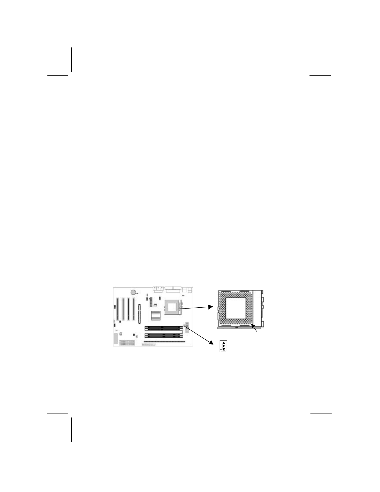
Install A CPU
This mainboard has a Socket-462 CPU socket for AMD K7
processors.
To ensure reliability, ensure that your processor has a
heatsink/cooling fan assembly.
Do not try to install a Socket-370/Socket-7 processor in the Socket-
462. A Socket-370/Socket-7 processor such as the PPGA Celeron,
FCPGA Pentium-III, Pentium-MMX, or the AMD K5/K6 does not
fit in the Socket-462.
The following list notes the processors that are currently supported
by this mainboard.
Athlon: 700 MHz~1.3 GHz, FSB: 200 MHz, 266 MHz
Duron: 600~950 MHz, FSB: 200 MHz
Installing a Socket-462 Processor
A processor installs into the ZIF (Zero Insertion Force) Socket-462
on the mainboard.
1. Locate the Socket-462 and CPUFAN1. Pull the locking lever
out slightly from the socket and raise it to the upright position.
2. On the processor, identify the Pin-1 corner by its beveled edge.
3. On the Socket-462, identify the Pin-1 corner. The Pin-1 corner
is at the top of the locking lever when it locked.
CPUFAN1
Socket-462
Pin-1 Corner

9
4. Match the Pin-1 corners and insert the processor into the
socket. No force is required and the processor should drop into
place freely.
5. Swing the locking lever down and hook it under the catch on
the side of the socket. This secures the CPU in the socket.
6. All processors should be installed with a combination
heatsink/cooling fan (the original fan is recommended, the
others’ fan is not), connect the cable from the fan to the CPU
fan power connector CPUFAN1.
See the Setting Jumper Switches section for detail information on
CPU System Bus settings.

10
Install Memory
The mainboard has two 168-pin/184-pin DIMM sockets for
SDRAM/DDR SDRAM (Double Data Rate SDRAM) system
memory modules. You must install at least one memory module in
order to use the mainboard, and you can only use one of the both
SDRAM and DDR SDRAM at the same time .
DDR SDRAM provides 800 MBps or 1 GBps data transfer
depending on whether the bus is 100 MHz or 133 MHz. It doubles
the rate to 1.6 GBps and 2.1 GBps by transferring data on both the
rising and falling edges of the clock. DDR SDRAM uses additional
power and ground lines and requires 184-pin 2.5V unbuffered
DIMM module reather than the 168-pin 3.3V unbuffered DIMMs
used by SDRAM.
For this mainboard, the maximum memory size is 1GB.
The edge connectors on the memory modules have cut outs, which
coincide with spacers in the DIMM sockets so that memory
module can only be installed in the correct orientation.
To install a module, push the retaining latches at either end of the
socket outwards. Position the memory module correctly and insert
it into the DIMM socket. Press the module down into the socket so
that the retaining latches rotate up and secure the module in place
by fitting into notches on the edge of the module.
The table below lists the model chips of DDR that we have
tested.
Model Chip Manufacture
K4H2808388-TCBO SAMSUNG
HY5DU28822T-HHYUNDAI
See the next section for detail information on SDRAM Type and
RAM Voltage settings.
DIMM1
DIMM2
DDR1
DDR2
11
Setting Jumper Switches
Jumpers are sets of pins which can be connected together with
jumper caps. The jumper caps change the way the mainboard
operates by changing the electronic circuits on the mainboard. If a
jumper cap connects two pins, we say the pins are SHORT. If a
jumper cap is removed from two pins, the pins are OPEN.
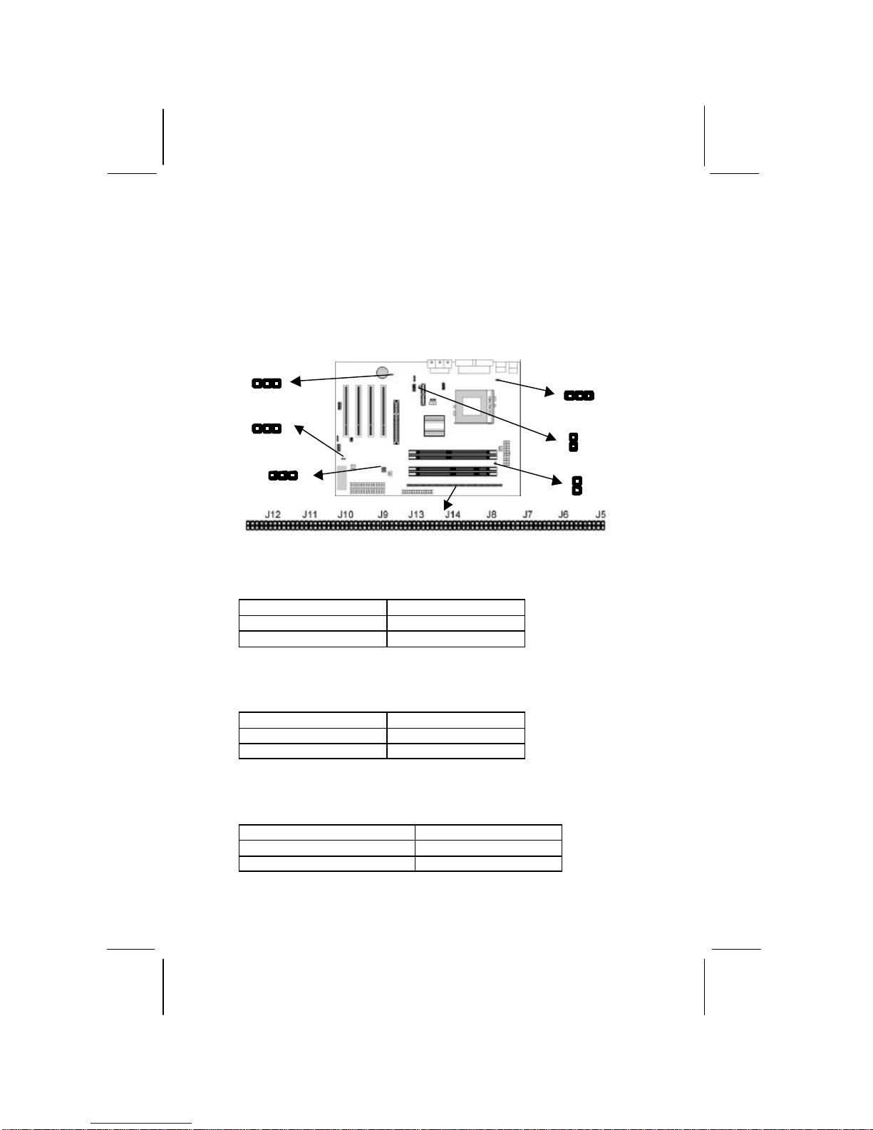
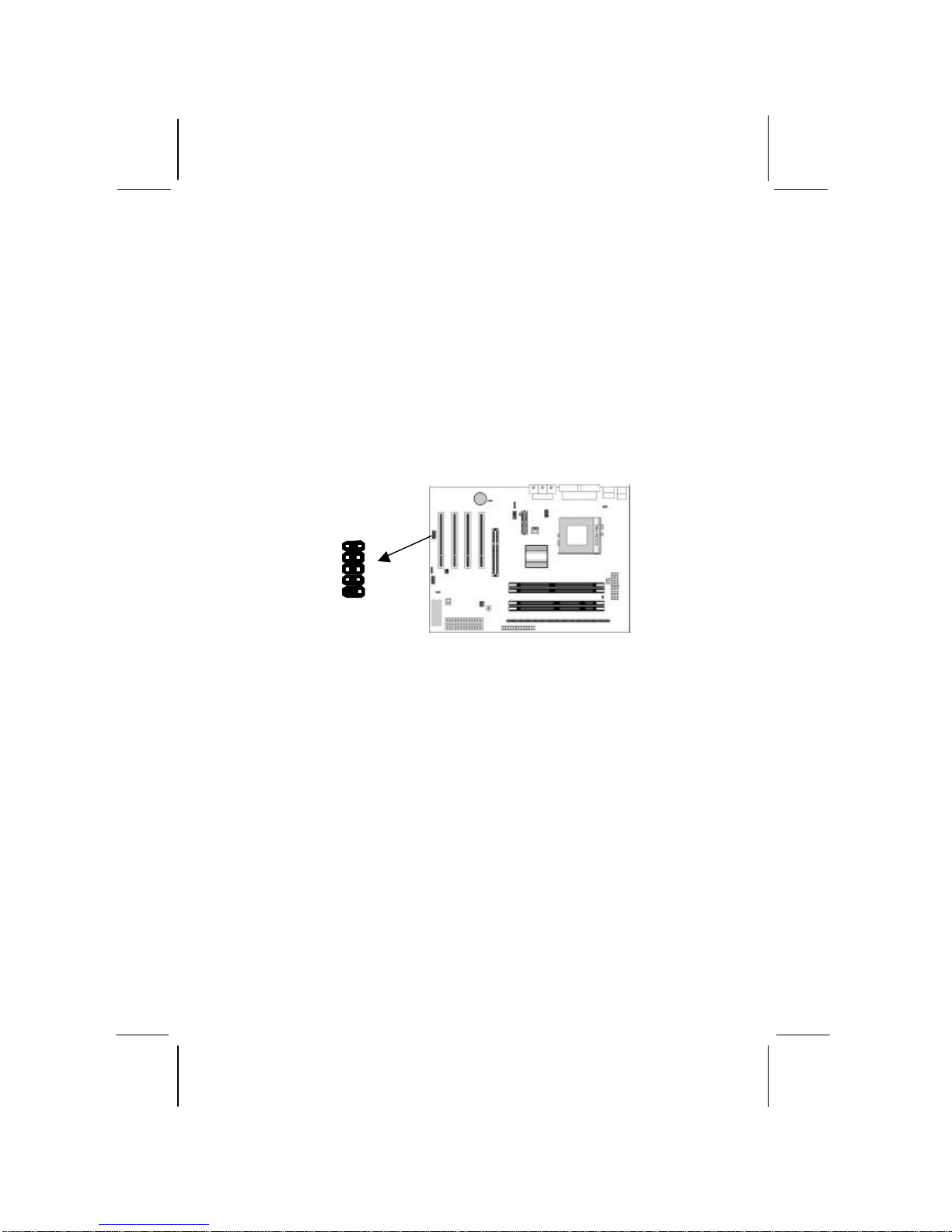
Jumper J5~J14: SDRAM Type Selector
The ten jumpers all consist of eight sets of 2-pin jumpers. Use
these jumpers to select the SDRAM type for the system memory.
Function Jumper Setting
DDR DIMM socket Short all Pins 1-2
SDRAM DIMM socket Open all Pins 1-2
Jumper JP1: RAM Voltage Selector
Use this 2-pin jumper to select the voltage for the installed
SDRAM module.
Function Jumper Setting
3.3V for SDRAM Short Pins 1-2
2.5V for DDR Open Pins 1-2
Jumper JP2: Codec Selector
Use this jumper to select the onboard audio codec or Audio
Modem Riser (AMR) slot.
Function Jumper Setting
Primary codec onboard Short Pins 1-2
Primary codec on AMR slot Open Pins 1-2
1
JP3
JP5
1
JP6
JP1
JP2A
1
1
JP2
12
Jumper JP2A: CPU System Bus Selector
Use this 3-pin jumper to select if the processor runs on 133 MHz or
100 MHz system bus.
Function JP2A
133 MHz system bus Short Pins 1-2
100 MHz system bus Short Pins 2-3
Jumper JP3: Keyboard Power On Selector
If you enable the keyboard power on feature, you can use hot keys
on your keyboard as a power on/off switch for the system.
Note: The system must provide 1A on the +5VSB (+5V
Standby) signal before using the Keyboard Power On
function.
Function Jumper Setting
Disable Keyboard Power On Short Pins 1-2
Enable Keyboard Power On Short Pins 2-3
Jumper JP5: Clear CMOS Memory
Use this jumper to clear the contents of the CMOS memory. You
may need to clear the CMOS memory if the settings in the Setup
Utility are incorrect and prevent your mainboard from operating.
To clear the CMOS memory, disconnect all the power cables from
the mainboard and then move the jumper cap into the CLEAR
setting for a few seconds.
Function Jumper Setting
Normal Operation Short Pins 1-2
Clear CMOS Memory Short Pins 2-3
Jumper JP6: Onboard LAN Selector
Use this 3-pin jumper to enable or disable the onboard network
adapter.
Function Jumper Setting
Enable Onboard LAN Short Pins 1-2
Disable Onboard LAN Short Pins 2-3
13
Install the Mainboard
Install the mainboard in a system chassis (case). The board is an
ATX size mainboard with a twin-tier of I/O ports. You can install
this mainboard in an ATX case. Ensure that your case has an I/O
cover plate that matches the ports on this mainboard.
Install the mainboard in a case. Follow the instructions provided by
the case manufacturer using the hardware and internal mounting
points on the chassis.
Connect the power connector from the power supply to the ATX1
connector on the mainboard.
If there is a cooling fan installed in the system chassis, connect the
cable from the cooling fan to the SYSTEMFAN1 fan power
connector on the mainboard.
Connect the cable from the PC speaker to the SPK1 header on the
mainboard.
Connect the case switches and indicator LEDs to the SW1 header.
If there are a headphone jack or/and a microphone jack on the front
panel, connect the cables to the AUDIO1 header on the mainboard.
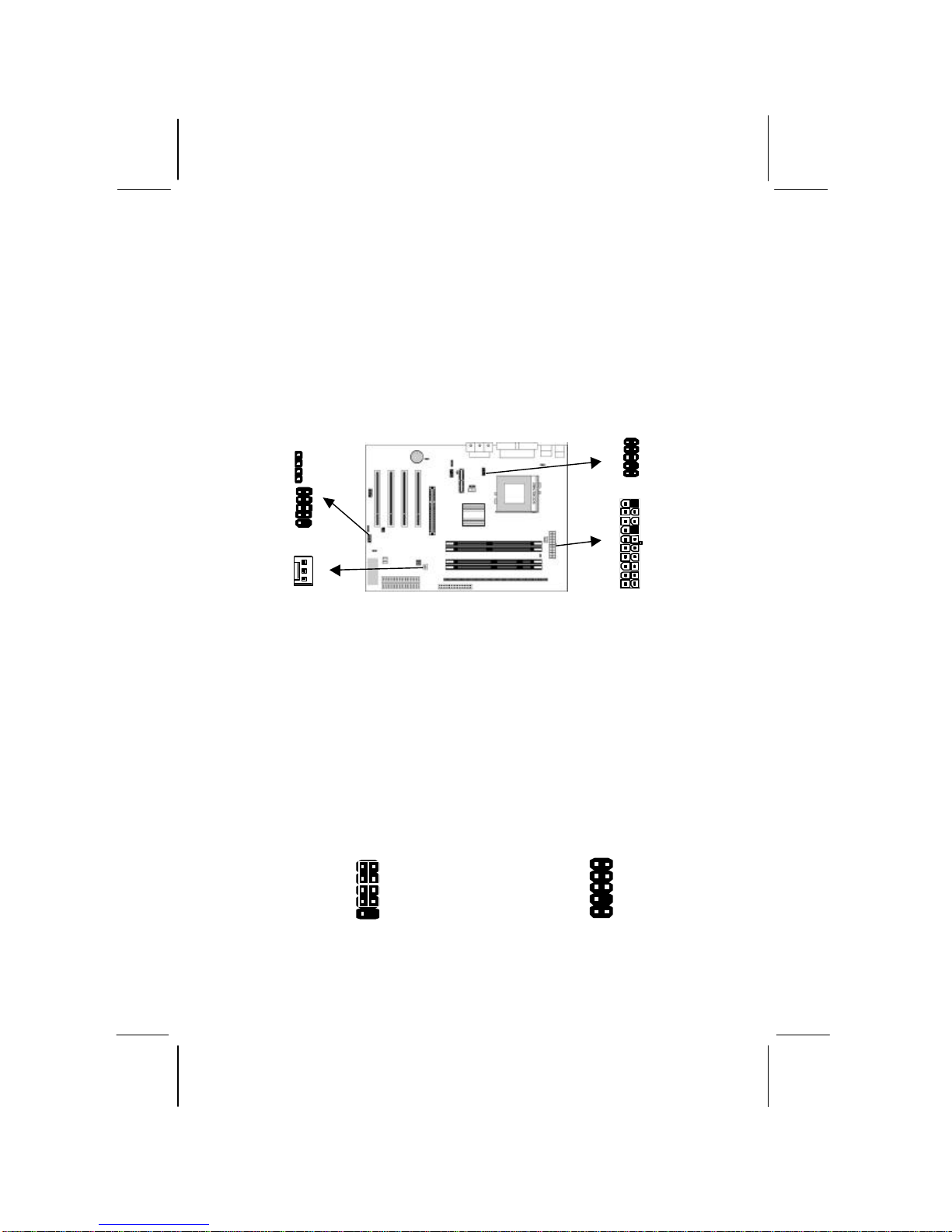
See the illustrations below for the guide to the SW1 and AUDIO1
headers pin assignments.
SW1
SYSTEMFAN1
ATX1
AUDIO1
SPK1
1
SW1
Power/ACPI LED P2-4
HDD LED P1-3
Reset Switch P5-7
Power Button P6-8
1 2
AUDIO1
MIC 1
MIC-
P 3
FPOUT-
R 5
NC 7
FPOUT-
L 9
2 GND
4 VCC
6 GND
8 Key
10 GND

14
Install the Extension Brackets
The extension brackets are used to connect features on the
mainboard to external connectors that can be attached to the system
chassis. Follow the steps below to install the extension brackets.
Note: All the ribbon cables used on the extension brackets
have a red stripe on the Pin-1 side of the cable.
LAN Adapter Extension Bracket (Optional)
This bracket supports an RJ45 network connector and connects to
the built in LAN header on the mainboard.
1. On the mainboard, locate the LAN header for this bracket.
2. Plug the cable from the bracket into the LAN header.
3. In the system chassis, remove a blanking plate from one of the
expansion slots and install the extension bracket in the slot.
Use the screw that held the blanking plate in place to secure
the extension bracket.
LAN Extension
Bracket
LAN Header
1
15
Optional Extension Brackets
For this mainboard, you can also obtain a USB module extension
bracket. Install them by following the steps below.
Note: All the ribbon cables used on the extension brackets
have a red stripe on the Pin-1side of the cable.
Extended USB Module
This module bracket has two USB ports for more USB devices
(USB port 3-4).
1. Locate the USB2 header on the mainboard.
2. Plug the bracket cable onto the USB2 header.
3. In the system chassis, remove a slot cover from one of the
expansion slots and install the extension bracket in the opening.
Use the screw that held the slot cover in place to secure the
extension bracket to the chassis.
USB2 Header
1
16
Install Other Devices
Install and connect any other devices in the system following the
steps below.
Floppy Disk Drive
The mainboard ships with a floppy disk drive cable that can
support one or two drives. Drives can be 3.5” or 5.25” wide, with
capacities of 360K, 720K, 1.2MB, 1.44MB, or 2.88MB.
Install your drives and connect power from the system power
supply. Use the cable provided to connect the drives to the floppy
disk drive connector FLOPPY1.
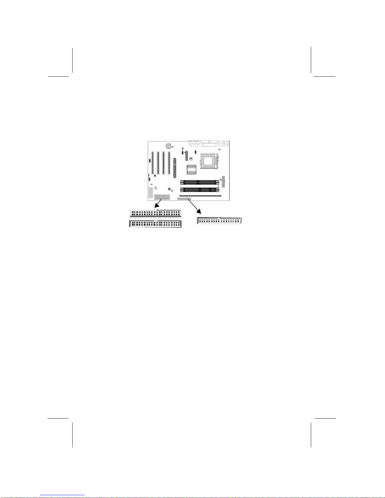
IDE Devices
IDE devices include hard disk drives, high-density diskette drives,
and CD-ROM or DVD-ROM drives, among others.
The mainboard ships with an IDE cable that can support one or two
IDE devices. If you connect two devices to a single cable, you
must configure one of the drives as Master and one of the drives as
Slave. The documentation of the IDE device will tell you how to
configure the device as a Master or Slave device. The Master
device connects to the end of the cable.
Install the device(s) and connect power from the system power
supply. Use the cable provided to connect the device(s) to the
Primary IDE channel connector IDE1 on the mainboard.
If you want to install more IDE devices, you can purchase a second
IDE cable and connect one or two devices to the Secondary IDE
IDE1
1
1
IDE2
FLOPPY1
1

17
channel connector IDE2 on the mainboard. If you have two
devices on the cable, one must be Master and one must be Slave.
Internal Sound Connections
If you have installed a CD-ROM drive or DVD-ROM drive, you
can connect the drive audio cable to the onboard sound system.
On the mainboard, locate the two 4-pin connectors CD1 and CD2.
There are two kinds of connector because different brands of CD-
ROM drive have different kinds of audio cable connectors.
Connect the cable to the appropriate connector.
Infrared Port
You can connect an infrared port to the mainboard. You can
purchase this option from third-party vendors.
1. Locate the infrared port IR1 header on the mainboard.
2. If you are adding an infrared port, connect the ribbon cable
from the port to the IR1 header and then secure the port to an
appropriate place in your system chassis.
Onboard LAN LED Connections
If you have a set indicator LEDs for the onboard LAN
communication, you can connect the LED cable to the header J15.
Pins 1-2 are for Link LED. Pins 3-4 are for 10/100 Mbps mode
LED, the onboard LAN run in 100 Mbps mode when the LED lit.
CD1
CD2
1
IR1
FIR 1
+5V 3
IRTX 5
2 Key
4 GND
6 IRRX
J15
1
+
+

18
Expansion Slots
This mainboard has four 32-bit PCI slots, one AGP slot and one
AMR slot.
Follow the steps below to install a PCI/AGP/AMR expansion card.
1. Locate the AMR, AGP or PCI slots on the mainboard.
2. Remove the slot cover for this slot from the system chassis.
3. Insert the expansion card edge connector into the slot and press
it firmly down into it so that it is fully inserted.
4. Secure the expansion card bracket to the system chassis using
the screw that held the slot cover in place.
AMR Slot
The AMR (Audio Modem Riser) slot is an industry standard slot
that allows for the installation of a special audio/modem riser card.
Different territories have different regulations regarding the
specifications of a modem card. You can purchase an AMR card
that is approved in your area and install it directly into the AMR
slot.
PCI1
PCI2
AMR1
AGP1
PCI3
PCI4
Table of contents
Other ECS Motherboard manuals


