ECS PT880PRO-A User manual


Preface
Preface
Copyright
This publication, including all photographs, illustrations and software, is protected under
international copyright laws, with all rights reserved. Neither this manual, nor any of the
material contained herein, may be reproduced without written consent of the author.
Version 1.0
Disclaimer
The information in this document is subject to change without notice. The manufacturer
makes no representations or warranties with respect to the contents hereof and specifically
disclaims any implied warranties of merchantability or fitness for any particular purpose.
The manufacturer reserves the right to revise this publication and to make changes from
time to time in the content hereof without obligation of the manufacturer to notify any
person of such revision or changes.
TrademarkRecognition
Microsoft, MS-DOS and Windows are registered trademarks of Microsoft Corp.
MMX, Pentium, Pentium-II, Pentium-III, Celeron are registered trademarks of Intel Cor-
poration.
Other product names used in this manual are the properties of their respective owners and
are acknowledged.
FederalCommunicationsCommission(FCC)
This equipment has been tested and found to comply with the limits for a Class B digital
device, pursuant to Part 15 of the FCC Rules. These limits are designed to provide reason-
able protection against harmful interference in a residential installation. This equipment
generates, uses, and can radiate radio frequency energy and, if not installed and used in
accordance with the instructions, may cause harmful interference to radio communications.
However, there is no guarantee that interference will not occur in a particular installation.
If this equipment does cause harmful interference to radio or television reception, which
can be determined by turning the equipment off and on, the user is encouraged to try to
correct the interference by one or more of the following measures:
• Reorient or relocate the receiving antenna
• Increase the separation between the equipment and the receiver
• Connect the equipment onto an outlet on a circuit different from that to which
the receiver is connected
• Consult the dealer or an experienced radio/TV technician for help
Shielded interconnect cables and a shielded AC power cable must be employed with this
equipment to ensure compliance with the pertinent RF emission limits governing this
device. Changes or modifications not expressly approved by the system’s manufacturer
could void the user’s authority to operate the equipment.

ii
Preface
DeclarationofConformity
This device complies with part 15 of the FCC rules. Operation is subject to the following
conditions:
• This device may not cause harmful interference, and
• This device must accept any interference received, including interference
that may cause undesired operation
CanadianDepartmentofCommunications
This class B digital apparatus meets all requirements of the Canadian Interference-causing
Equipment Regulations.
Cet appareil numérique de la classe B respecte toutes les exigences du Réglement sur le
matériel brouilieur du Canada.
AbouttheManual
The manual consists of the following:
Chapter 1
Introducing the Motherboard
Chapter 2
Installing the Motherboard
Chapter 3
UsingBIOS
Chapter 4
Using the Motherboard Software
Chapter 5
VIAVT8237 SATA RAID
SetupGuide
Describes features of the motherboard.
Go to Hpage 1
Describes installation of motherboard
components.
Goto Hpage 7
Provides information on using the BIOS
Setup Utility.
Go to Hpage 27
Describes the motherboard software
Go to Hpage 39
Describes the information about SATA
RAID Setup
Go to Hpage 43

iii
TT
TT
TABLE OF CONTENTSABLE OF CONTENTS
ABLE OF CONTENTSABLE OF CONTENTS
ABLE OF CONTENTS
Preface i
Chapter 1
1
IntroducingtheMotherboard 1
Introduction.................................................................................................1
Feature..........................................................................................................2
MotherboardComponents........................................................................4
Chapter 2 77
77
7
Installing the Motherboard 7
SafetyPrecautions......................................................................................7
Choosinga ComputerCase.......................................................................7
Installingthe Motherboard ina Case......................................................7
CheckingJumperSettings.........................................................................8
Setting Jumpers..............................................................................8
Checking Jumper Settings..............................................................9
Jumper Settings..............................................................................9
ConnectingCase Components...............................................................10
Front Panel Connector.................................................................12
InstallingHardware...................................................................................13
Installing the Processor...............................................................13
Installing Memory Modules.........................................................15
Installing a Hard Disk Drive/CD-ROM/SATA Hard Drive........17
Installing a Floppy Diskette Drive...............................................19
Installing Add-on Cards..............................................................20
Connecting Optional Devices......................................................23
ConnectingI/ODevices..........................................................................26
Chapter 3 2727
2727
27
UsingBIOS 27
Aboutthe SetupUtility............................................................................27
The Standard Configuration........................................................27
Entering the Setup Utility..............................................................27
Updating the BIOS.......................................................................29
UsingBIOS................................................................................................29
Standard CMOS Setup.................................................................30
Advanced Setup............................................................................30
Features Setup.............................................................................32

iv
Power Management Setup...........................................................33
PCI/Plug and Play Setup.............................................................34
BIOS Security Features................................................................35
CPU PnP Setup............................................................................36
Hardware Monitor.......................................................................37
Load Best Performance Settings..................................................38
Load Optimal Defaults................................................................38
Save Changes and Exit................................................................38
Discard Changes and Exit...........................................................38
Chapter 4 3939
3939
39
UsingtheMotherboardSoftware 39
AbouttheSoftwareCD-ROM................................................................39
Auto-installingunderWindows 98/ME/2000/XP................................39
Running Setup..............................................................................40
ManualInstallation..................................................................................42
UtilitySoftwareReference.......................................................................42
Multi-Language Translation
Chapter 5 4343
4343
43
VIAVT8237SATARAIDSetupGuide 43
VIARAIDConfigurations.......................................................................43
InstallingRAID Software&Drives.......................................................51
UsingVIARAIDTool.............................................................................52

1
IntroducingtheMotherboard
Chapter1
IntroducingtheMotherboard
Introduction
Thank you for choosing the PT880PRO-A motherboard. This motherboard is a high
performance, enhanced function motherboard that supports LGA775 Pentium 4/Celeron
processors for high-end business or personal desktop markets.
The motherboard incorporates the PT880Pro Northbridge (NB) and VT8237 Southbridge
(SB) chipsets. The Northbridge supports a Front Side Bus (FSB) frequency of 800/533 MHz
FSB and Hyper-Threading technology. The momory controller supports DDR memory
DIMM frequencies of 400/333/266 MHz or DDR2 memory DIMM frequencies of 533/400
MHz. It supports four DDR Sockets with up to maximum memory of 2 GB. DDR Maximum
memory bandwidth of 3.2 GB/s in single-channel is supported, or 8.5 GB/s in dual-channel
interleaved mode assuming DDR2 533 MHz. Aside from the onboard AGP slot, one PCI
Express Lite slot, intended for Graphics Interface, is fully compliant to the PCI Express
Base Specification revision 1.0a.
The VT8237 Southbridge is a highly integrated peripheral controller, it includes an inte-
grated keyboard controller with PS2 mouse support, two-channel Serial ATA/RAID hard
disk controller, master mode enhanced Parallel IDE controller with full scatter/gather
capability and extension to UltraDMA-133/100/66 for 133/100/66 MB/sec transfer rate,
integrated USB 2.0 interface, supporting up to eight functional ports, and OnNow/ACPI
compliant advanced configuration and power management interface. The VT8237 inte-
grated networking MAC controller with standard MII interface to an external PHY for 100/
10/1Mb Base-T Ethernet.
The PT880PRO-A motherboard is equipped with advanced full set of I/O ports in the rear
panel, including PS/2 mouse and keyboard connectors, COM1, LPT1, four USB ports, one
optional LAN port, and audio jacks for microphone, line-in and line out.

2
IntroducingtheMotherboard
Feature
• Accommodates Intel P4/Celeron processors
• Supports a system bus (FSB) of 800/533MHz
• Supports “Hyper-Threading” technology CPU
The PT880Pro Northbridge (NB) and VT8237 Southbridge (SB) chipset is based on an
innovative and scalable architecture with proven reliability and performance.
PT880Pro
(NB) • High performance Northbridge with 800MHz FSB for P4/
Celeron processors plus PCI Express and AGP bus
• UltraV-link 1066 MB/sechigh bandwidth North/South Bridge
interconnect
• Supports for AGP 8X/4X, AGP v3.0 compliant
• Supports one PCI Express Lite slot for Graphics Interface
• Advanced high-performance 128-bit, Dual-Channel, DDR
SDRAM controller
“Hyper-Threading” technology enables the operating system into thinking it’s hooked
up to two processors, allowing two threads to be run in parallel, both on separate
“logical” processors within the same physical processor.
PT880PRO-A uses an LGA775 type of Pentium 4 that carries the following features:
Processor
Chipset
• SupportsDDR 400/333/266 MHzor DDR2 533/400DDR SDRAM DIMMs
• Accommodates four unbuffered DIMMs
• Up to 1 GB per DIMM with maximum memory size up to 2 GB
Memory
PT880Pro chipset can only support mixed 2048/1024/512/256/
128/64Mb x8/16 DDR2 SDRAMs or mixed 1024/512/256/128/
64Mb x8/16 DDR SDRAMs.
Users please note that DDR & DDR2 can’t both be applied at the same time on
this motherboard. Users can use either DDR or DDR2 memory modules only!
VT8237(SB) • Supports 16-bit 66 MHz V-Link Host interface with total
bandwidth of 1066 MB/s
• Compliant with PCI 2.2 specification at 33 MHz, supporting
up to 6 PCI masters
• IntegratedSerialATAHost Controllers, supporting data trans-
fer rates up to 1.5Gb/s
• IntegratedDual channel UltraDMA 133/100/66Master Mode
EIDEController
• USB 2.0 Controller, supporting up to 8 USB 2.0 ports
• Network Controller, supporting enterprise class 100/10 Mb
Fast Ethernet MAC
• Integrated keyboard Controller with PS2 mouse support

3
IntroducingtheMotherboard
• Power management
• Wake-up alarms
• CPUparameters
• CPUandmemroytiming
Some hardware specifications and software items are subject to change
with out prior notice.
BIOS Firmware
This motherboard uses AWARD BIOS that enables users to configure many system
features including the following:
The firmware can also be used to set parameters for different processor clock speeds.
• Two PS/2 ports for mouse and keyboard
• One serial port
• One parallel port
• Four USB ports
• One LAN port (optional)
• Audio jacks for microphone in, line-in and line-out
Integrated I/O
The motherboard has a full set of I/O ports and connectors:
• Compliant with AC’97 2.3 specification
• 16-bit Stereo full-duplex CODEC with 48KHz sampling rate
• Supports double sampling rate (96KHz) of DVD audio playback
• Direct Sound 3DTM compatible
Audio
The PT880PRO-A motherboard supports UltraDMA bus mastering with transfer rates
of 133/100/66 MB/s.
The motherboard comes with the following expansion options:
Expansion Options
• OneAGP slot
• One PCI Express Lite slot for Graphic Interface
• Four 32-bit PCI v2.2 compliant slots
• Two 40-pin IDE low profile connectors supporting up to 4 IDE devices
• One floppy disk drive interface
• Two 7-pin SATA connectors
• One Communications Networking Riser (CNR) slot
• Single chip 100Base-TX/10Base-T physical layer solution
• Dual speed 100/10 Mbps, half and full duplex with auto negotiation
• MII interface to Ethernet controller
• Meets all applicable IEEE 802.3, 10Base-T and 100Base-Tx standards
Onboard LAN (Optional)
The onboard LAN controller provides the following features:
4
IntroducingtheMotherboard
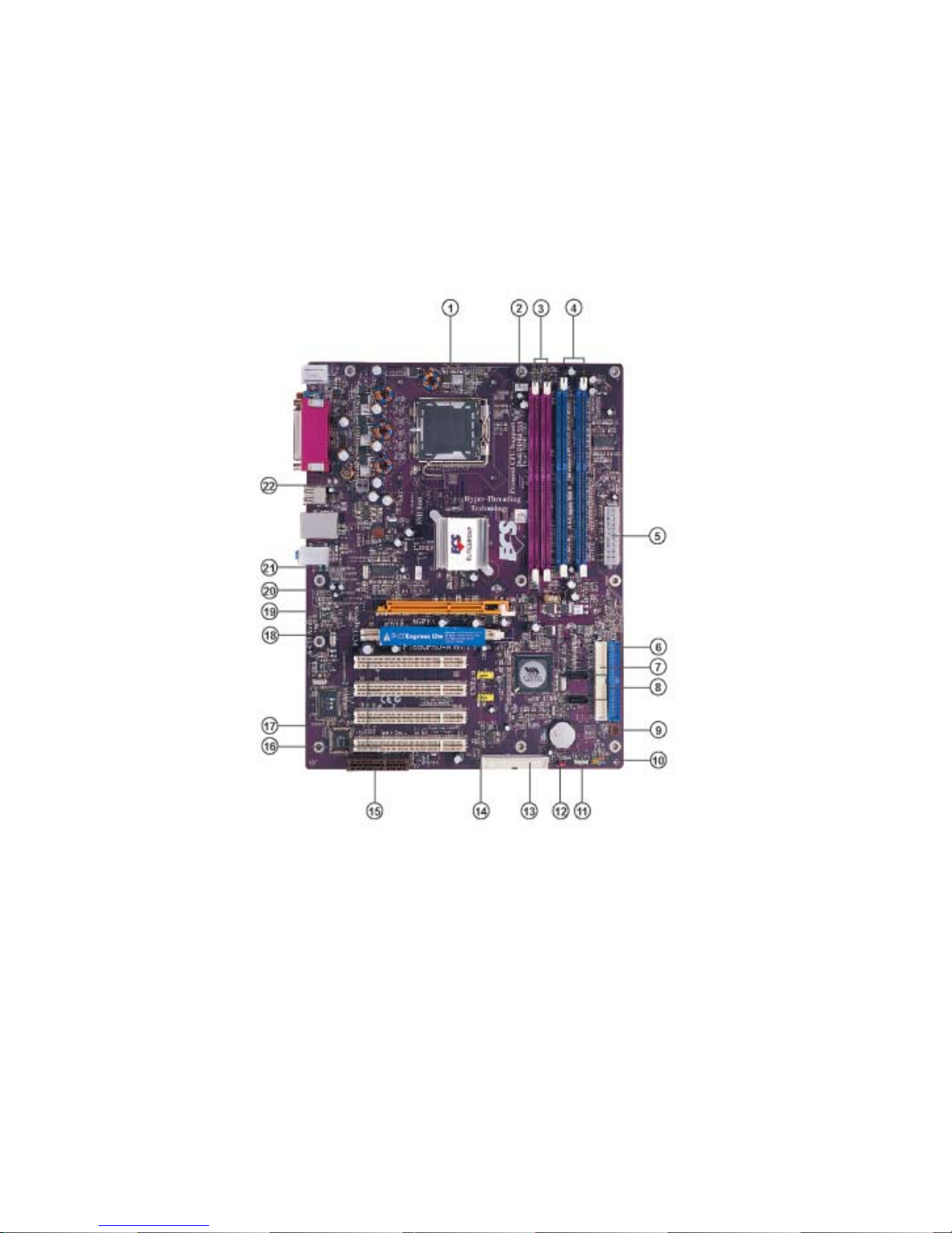
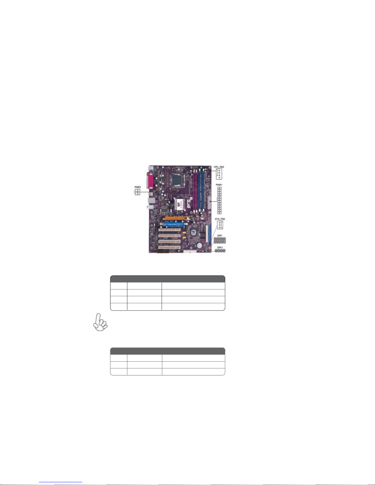
MotherboardComponents
5
IntroducingtheMotherboard
Table of Motherboard Components
This concludes Chapter 1. The next chapter explains how to install the motherboard.
1 CPU Socket LGA775 socket for Pentium 4 CPUs
2 CPU_FAN CPU cooling fan connector
22 PWR2 Auxiliary 4-pin power connector
18 PCI-E PCI Express Lite graphics card slot
14 USB2-3 Front Panel USB headers
8 SATA1~2 Serial ATA connectors
12 JCMOS1 Clear CMOS jumper
5 PWR1 Standard 20-pin ATX power connector
10 SW1 Panel connector for case switches and LEDs
13 FDD1 Floppy diskette drive connector
16 PCI1~4 32-bit add-on card slots
20 JCDIN1 Analog audio input header
21 AUDIO1 Front panel audio header
LABEL COMPONENT
6 IDE1 Primary IDE channel
3 DIM1~2 240-pin DDR2 SDRAM slots
4 DIMMA1~DIMMB1 184-pin DDR SDRAM slots
9 SYS_FAN System cooling fan connector
17 IR1 Internal infrared header
19 AGP Accelerated Graphics Port slot
Users please note that DDR & DDR2 can’t both be applied at the same time on
this motherboard. Users can use either DDR or DDR2 memory modules only!
7 IDE2 Secondary IDE channel
11 SPK1 Speaker header
15 CNR1 Communications Networking Riser slot

6
IntroducingtheMotherboard
Memo

7
InstallingtheMotherboard
Chapter2
InstallingtheMotherboard
Installingthe Motherboard inaCase
Refer to the following illustration and instructions for installing the motherboard in a case.
SafetyPrecautions
• Follow these safety precautions when installing the motherboard
• Wear a grounding strap attached to a grounded device to avoid damage from
static electricity
• Discharge static electricity by touching the metal case of a safely grounded
object before working on the motherboard
• Leave components in the static-proof bags they came in
• Hold all circuit boards by the edges. Do not bend circuit boards
ChoosingaComputer Case
There are many types of computer cases on the market. The motherboard complies with
the specifications for the ATX system case. First, some features on the motherboard are
implemented by cabling connectors on the motherboard to indicators and switches on the
system case. Make sure that your case supports all the features required. Secondly,
PT880PRO-A supports one or two floppy diskette drives and four enhanced IDE drives.
Make sure that your case has sufficient power and space for all drives that you intend to
install.
Most cases have a choice of I/O templates in the rear panel. Make sure that the I/O
template in the case matches the I/O ports installed on the rear edge of the motherboard.
This motherboard carries a ATX form factor of 305 x 244 mm. Choose a case that
accommodates this form factor.
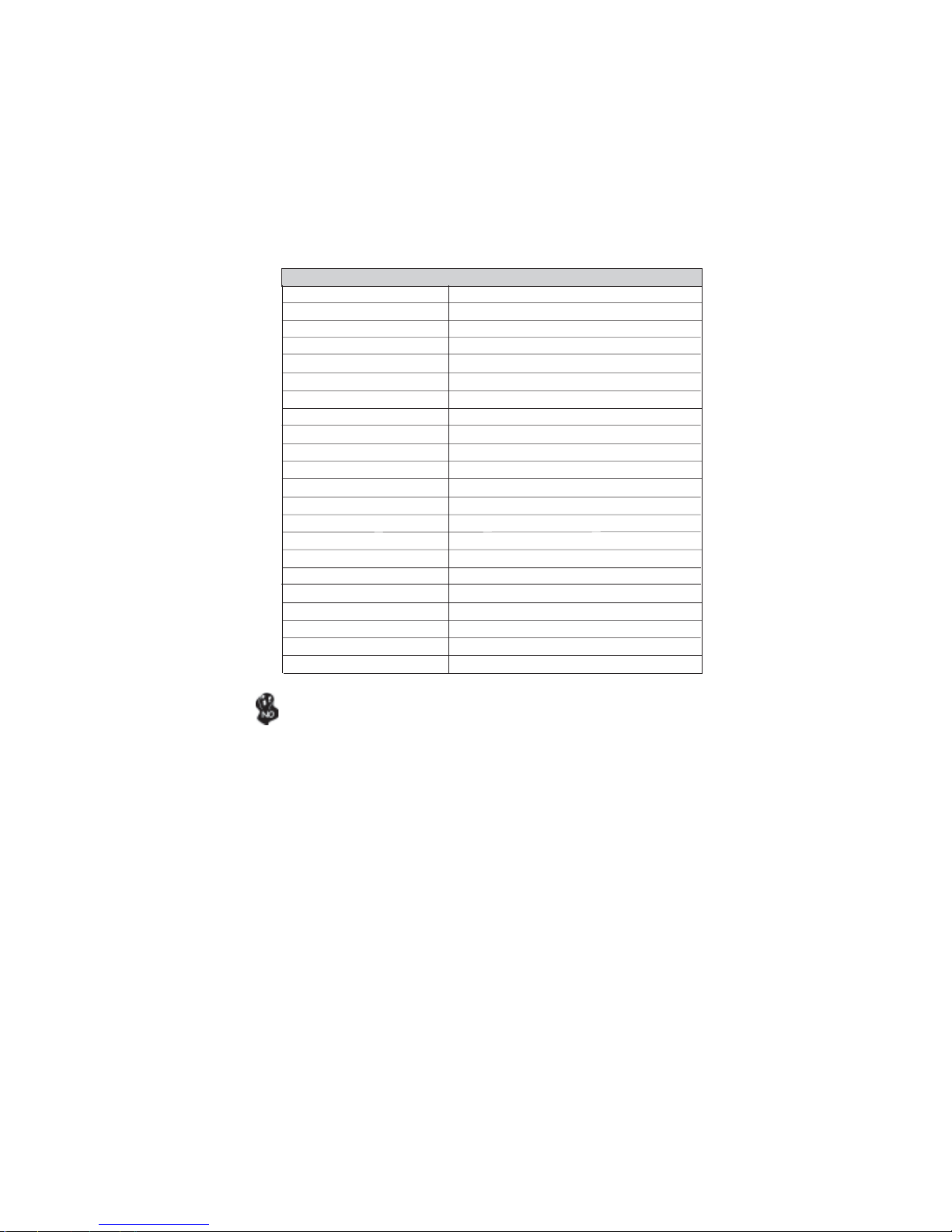
Most system cases have mounting brackets installed in the case, which correspond the holes
in the motherboard. Place the motherboard over the mounting brackets and secure the
motherboard onto the mounting brackets with screws.
Ensure that your case has an I/O template that supports the I/O ports and expansion slots
on your motherboard.
8
InstallingtheMotherboard
CheckingJumperSettings
This section explains how to set jumpers for correct configuration of the motherboard.
SettingJumpers
Use the motherboard jumpers to set system configuration options. Jumpers with more than
one pin are numbered. When setting the jumpers, ensure that the jumper caps are placed on
the correct pins.
The illustrations show a 2-pin jumper. When
the jumper cap is placed on both pins, the
jumper is SHORT. If you remove the jumper
cap, or place the jumper cap on just one pin,
the jumper is OPEN.
This illustration shows a 3-pin jumper. Pins
1 and 2 are SHORT
SHORT OPEN
Do not over-tighten the screws as this can stress the motherboard.
9
InstallingtheMotherboard
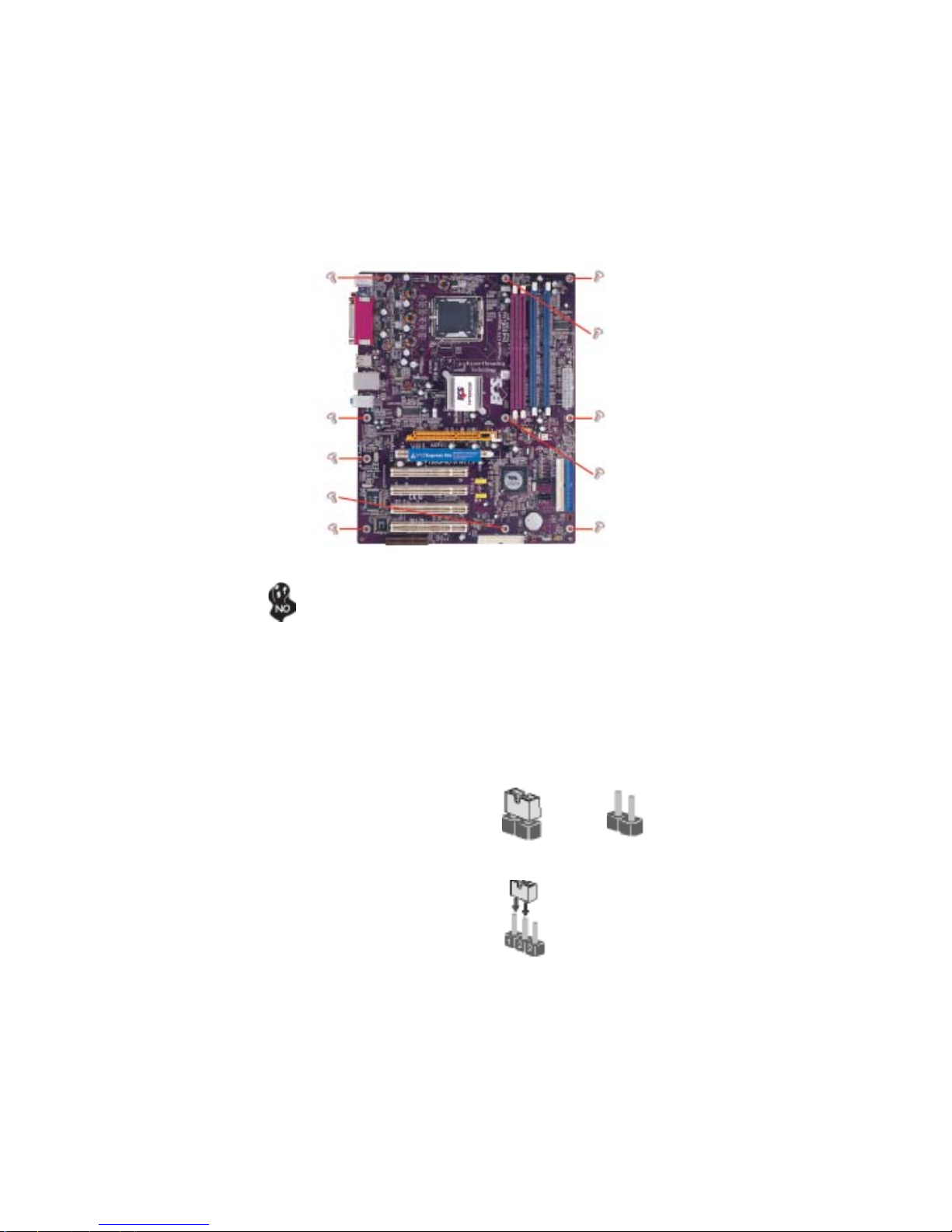
Checking Jumper Settings
The following illustration shows the location of the motherboard jumpers. Pin 1 is labeled.
JumperSettings
Jumper Type Description Setting (default)
JCMOS1 3-pin CLEAR CMOS
1-2: NORMAL
2-3: CMOS CLEAR
Before clearing the
CMOS, make sure to
turn off the system.
To avoid the system unstability after clearing CMOS, we recommend
users to enter the main BIOS setting page to “Load Optimal De-
faults” and then “Save Changes and Exit”.
1
JCMOS1
10
InstallingtheMotherboard
ConnectingCaseComponents
After you have installed the motherboard into a case, you can begin con-
necting the motherboard components. Refer to the following:
1 Connect the CPU cooling fan cable to CPU_FAN.
2 Connect the system cooling fan connector to SYS_FAN.
3 Connect the case speaker calbe to SPK1.
4 Connect the case switches and indicator LEDs to the SW1.
5 Connect the standard power supply connector to PWR1.
6 Connect the auxiliary case power supply connector to PWR2.
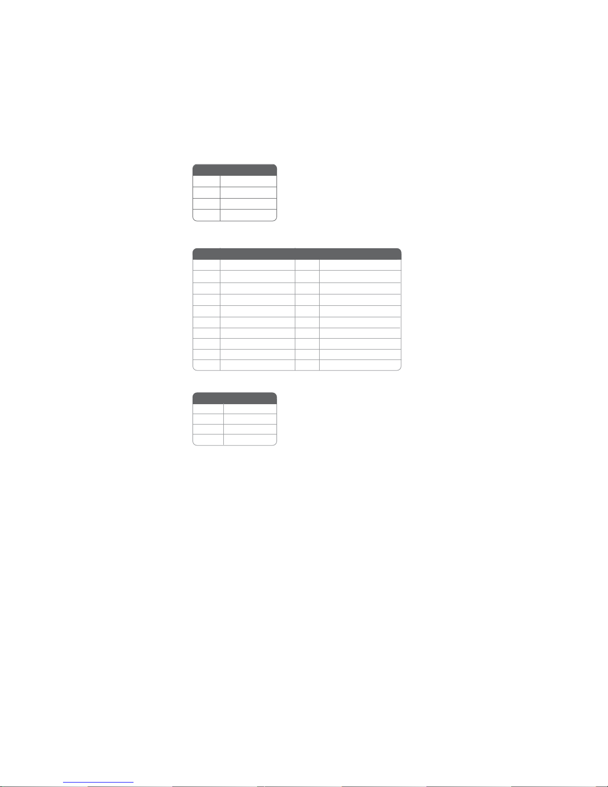
CPU_FAN:CPU FAN PowerConnector
SYS_FAN: System coolingFAN Power Connector
Users please note that the fan connector supports the CPU cooling
fan of 1.1A~2.2A (26.4W max.) at +12V.
Pin Signal Name Function
1GND System Ground
2+12V Power +12V
3 Sense Sensor
4 PWM CPU FAN control
Pin Signal Name Function
1GND System Ground
2+12V Power +12V
3 Sense Sensor
11
InstallingtheMotherboard
PWR2:ATX 12V Power Connector
PWR1:ATX 24-pin Power Connector
Pin Signal Name
4+12V
3+12V
2Ground
1Ground
1+3.3V 11 +3.3V
2+3.3V 12 -12V
10 +12V 20 +5V
3Ground 13 Ground
4+5V 14 PS ON#
5Ground 15 Ground
6+5V 16 Ground
7Ground 17 Ground
8PWRGD 18 -5V
9+5VSB 19 +5V
Pin Signal Name Pin Signal Name
SPK1: Internal Speaker Header
Pin Signal Name
1VCC
2NC
4Signal
3Ground
12
InstallingtheMotherboard
Power/Sleep/Message waiting LED
Connecting pins 2 and 4 to a single or dual-color, front panel mounted LED provides power
on/off, sleep, and message waiting indication.
Reset Switch
Supporting the reset function requires connecting pin 5 and 7 to a momentary-contact
switch that is normally open. When the switch is closed, the board resets and runs POST.
Power Switch
Supporting the power on/off function requires connecting pins 6 and 8 to a momentary-
contact switch that is normally open. The switch should maintain contact for at least 50 ms
to signal the power supply to switch on or off. The time requirement is due to internal de-
bounce circuitry. After receiving a power on/off signal, at least two seconds elapses before
the power supply recognizes another on/off signal.
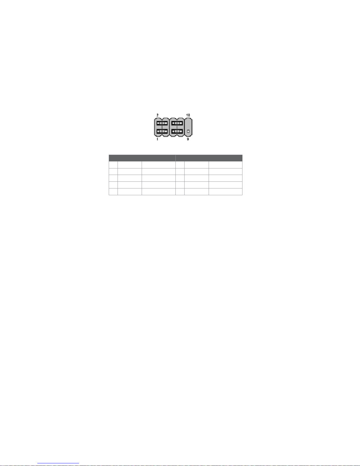
Front Panel Connector
The front panel connector (SW1) provides a standard set of switch and LED connectors
commonly found on ATX or micro-ATX cases. Refer to the table below for information:
Pin Signal Function Pin Signal Function
1 HD_LED_P Hard disk LED(+) 2 FP PWR/SLP *MSG LED(+)
3 HD_LED_N Hard disk LED(-)
5 RST_SW_N Reset Switch(-)
7 RST_SW_P Reset Switch(+)
9 RSVD Reserved
4 FP PWR/SLP *MSG LED(-)
6 PWR_SW_P Power Switch(+)
8 PWR_SW_N Power Switch(-)
10 Key No pin
* MSG LED (dual color or single color)
Hard Drive Activity LED
Connecting pins 1 and 3 to a front panel mounted LED provides visual indication that data
is being read from or written to the hard drive. For the LED to function properly, an IDE
drive should be connected to the onboard IDE interface. The LED will also show activity
for devices connected to the SCSI (hard drive activity LED) connector.
SW1

13
InstallingtheMotherboard
InstallingHardware
Installing the Processor
Caution: When installing a CPU heatsink and cooling fan make sure that
you DO NOT scratch the motherboard or any of the surface-mount
resistors with the clip of the cooling fan. If the clip of the cooling fan
scrapes across the motherboard, you may cause serious damage to the
motherboard or its components.
On most motherboards, there are small surface-mount resistors near the
processor socket, which may be damaged if the cooling fan is carelessly
installed.
Avoid using cooling fans with sharp edges on the fan casing and the clips.
Also, install the cooling fan in a well-lit work area so that you can clearly
see the motherboard and processor socket.
Before installing the Processor
This motherboard automatically determines the CPU clock frequency and system bus
frequency for the processor. You may be able to change these settings by making changes
to jumpers on the motherboard, or changing the settings in the system Setup Utility. We
strongly recommend that you do not over-clock processors or other components to run
faster than their rated speed.
This motherboard has a LGA 775 socket. When choosing a processor, consider the perfor-
mance requirements of the system. Performance is based on the processor design, the clock
speed and system bus frequency of the processor, and the quantity of internal cache memory
and external cache memory.
Warning: Over-clocking components can adversely affect the reliability
of the system and introduce errors into your system. Over-clocking can
permanently damage the motherboard by generating excess heat in
components that are run beyond the rated limits.
14
InstallingtheMotherboard
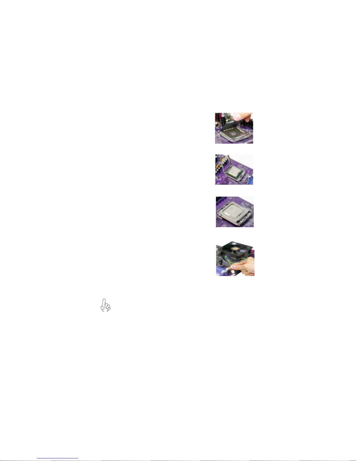
A. Unload the cap
· Use thumb & forefinger to hold the
lifting tab of the cap.
· Lift the cap up and remove the cap
completely from the socket.
B. Open the load plate
· Use thumb & forefinger to hold the
hook of the lever, pushing down and pulling
aside unlock it.
· Lift up the lever.
· Use thumb to open the load plate. Be
careful not to touch the contacts.
C. Install the CPU on the socket
· Orientate CPU package to the socket.
Make sure you match triangle marker
to pin 1 location.
D. Close the load plate
· Slightly push down the load plate onto the
tongue side, and hook the lever.
· CPU is locked completely.
E. Apply thermal grease on top of the CPU.
F. Fasten the cooling fan supporting base onto
the CPU socket on the motherboard.
G. Make sure the CPU fan is plugged to the
CPU fan connector. Please refer to the CPU
cooling fan user’s manual for more detail
installation procedure.
CPU Installation Procedure
The following illustration shows CPU installation components.
To achieve better airflow rates and heat dissipation, we suggest that you use
a high quality fan with 3800 rpm at least. CPU fan and heatsink installa-
tion procedures may vary with the type of CPU fan/heatsink supplied. The
form and size of fan/heatsink may also vary.
Table of contents
Languages:
Other ECS Motherboard manuals


