ECS P6BAT-B User manual

Important Information
Copyright
This publication, including all photographs, illustrations and software, is
protected under international copyright laws, with all rights reserved.
Neither this manual, nor any of the material contained herein, may be
reproduced without the express written consent of the manufacturer.
Disclaimer
The information in this document is subject to change without notice.
The manufacturer makes no representations or warranties with respect
to the contents hereof and specifically disclaims any implied warranties
of merchantability or fitness for any particular purpose. Further, the
manufacturer reserves the right to revise this publication and to make
changes from time to time in the content hereof without obligation of the
manufacturer to notify any person of such revision or changes.
Trademark Recognition
Microsoft, MS-DOS and Windows are registered trademarks of Microsoft
Corp.
MMX, Pentium, Pentium-II, Pentium-III, Celeron are registered
trademarks of Intel Corporation.
VGA, OS/2, PS/2 are registered trademarks of International Business
Machines.
AMD, K5, K6 are registered trademarks of Advanced Micro Devices Inc.
Cyrix, M1 are registered trademarks of Cyrix Corporation.
Other product names used in this manual are the properties of their
respective owners and are acknowledged.
Version 1.5

Contents
Chapter 1: Introduction.............................................. 1
Welcome....................................................................... 1
About the Manual.......................................................... 2
Checklist ....................................................................... 3
Standard Items------------------------------------------------- 3
Recommendations........................................................ 3
Features........................................................................ 4
Chapter 2: Installation................................................ 7
Quick Installation Table ................................................ 7
Quick Jumper Setting Reference ................................. 8
Before You Begin.......................................................... 10
Static Electricity------------------------------------------------ 10
Choosing a Case---------------------------------------------- 10
How to Set Jumpers ------------------------------------------ 11
Preparing the Mainboard .............................................. 12
Mainboard Guide---------------------------------------------- 12
Check the Jumper Settings --------------------------------- 14
Install the Mainboard in the Case................................. 17
Connecting Power, Chassis Fans, and Panel---------- 19
Install Other Hardware.................................................. 21
Install the Processor------------------------------------------ 21
Installing a Slot1 Processor--------------------------------- 23
Installing a Socket-370 Processor ------------------------ 25
Install the Memory Modules -------------------------------- 27
Install a Hard Disk Drive and CD-ROM/DVD----------- 28
Installing a Floppy Diskette Drive ------------------------- 31
Using the Expansion Slots ---------------------------------- 32
Add-in Card Options------------------------------------------ 34
Install Extension Brackets and Modules----------------- 35

Chapter 3: Setup ......................................................... 41
About the Setup Utility .................................................. 41
Starting the Setup Utility -------------------------------------41
How to Flash a New BIOS-----------------------------------43
Standard CMOS Setup Option ..................................... 44
BIOS & CPU Features Setup Option............................ 45
Chipset Features Option............................................... 48
Power Management Setup Option ............................... 50
PNP/PCI Configuration Option ..................................... 53
Load BIOS Defaults Option .......................................... 54
Load Optimum Settings ................................................ 54
Integrated Peripherals Option....................................... 55
Supervisor and User Password Settings...................... 57
IDE HDD Auto Detection Option................................... 57
Save And Exit Setup Option ......................................... 58
Exit Without Saving Option........................................... 58
Chapter 4: Software.................................................... 59
About the Software ....................................................... 59
Folders for this Mainboard............................................ 59
Running the Support CD-ROM..................................... 61
Utility Folder Installation Notes ..................................... 61
CMI8X38 Folder Installation Notes............................... 62
Audio Software -------------------------------------------------62
Modem Driver and Software --------------------------------63
VIA Folder Installation Notes ........................................ 63
Mainboard (KOB 693 DCS) Installation Notes ............. 64
Appendix 1: Quick Jumper Setting Reference ........ 65
C
Ch
ha
ap
pt
te
er
r
1
1:
:
I
In
nt
tr
ro
od
du
uc
ct
ti
io
on
n
Welcome
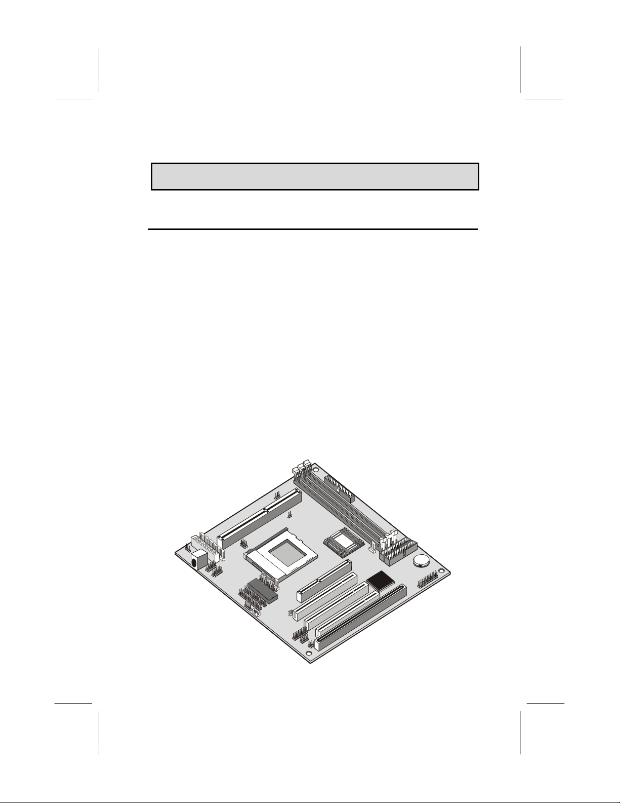
Congratulations on purchasing the KOB 693 DCS mainboard. The
mainboard includes a Slot1 processor slot and a FC-PGA (Flip-Chip
Plastic Pin Grid Array) Socket-370 processor socket. This feature
means that you can install the mainboard with a Pentium-II or
Pentium-III cartridge, the SEPP (Single Edge Processor Package)
Celeron cartridge, or one of the new generation PGA Celeron or FC-
PGA Coppermine processors.
The KOB 693 DCS is a baby-AT sized mainboard that uses 4-layer
printed circuit board and measures 22cm x 22cm. The mainboard
features the VIA Apollo Pro Plus chipset. The KOB 693 DCS has a slot1
and a socket-370 so that it can be installed with either a slot1 processor
(SEPP Celeron, Pentium-II, Pentium-III) or a socket-370 processor (PGA
Celeron/FC-PGA Coppermine processor). The mainboard includes an
integrated audio system and a plug-in fax/modem module. The board
has an AGP slot for a graphics adapter, three PCI slots and one legacy
ISA slot. The mainboard has power connectors for both ATX and AT
power supplies, so that it can be installed in practically any kind of PC
case.
1

This chapter contains the following information:
About the Manual explains how the information in this manual is
organized
Checklist comprises a list of the standard and optional components
that are shipped with this mainboard
Recommendations lists some Do’s and Don’ts from the
manufacturer to help ensure reliability and performance from this
product
Features highlights the functions and components that make this
one of the best value mainboards on the market
About the Manual
The manual consists of the following chapters:
Introduction
Use the Introduction Chapter to learn about the features of the
mainboard, and the checklist of items that are shipped with the package.
Installation
Use the Installation Chapter to learn how to install the mainboard and
get your system up and running.
Setup
Use the Setup Chapter to configure the mainboard for optimum
performance.
Software
Use the Software Chapter to learn how to use the software drivers and
support programs that are provided with this mainboard.
2

Checklist
Compare the contents of your mainboard package with the standard
checklist below. If any item is missing or appears damaged, please
contact the vendor of your mainboard package.
Standard Items
1 x KOB 693 DCS Mainboard
1 x Cable/Bracket Pack
Diskette drive ribbon cable
IDE drive ribbon cable
Parallel port extension bracket
Serial ports extension bracket
Audio ports extension bracket
This User’s Manual
Software Support CD-ROM Disc
Optional Items
ATX Form Bracket (2 USB ports, IR port, PS/2 mouse port)
Digital audio extension bracket
V.90 Fax/modem module
Recommendations
This mainboard automatically determines the CPU clock frequency and
system bus frequency for the kind of processor that you install. You may
be able to change these automatic settings by making changes to
jumpers on the mainboard, or changing the settings in the system setup
utility. We strongly recommend that you do not overclock the mainboard
to run processors or other components faster than their rated speed.
Overclocking components can adversely affect the reliability of the
system and introduce errors into your system. Overclocking can
permanently damage the mainboard by generating excess heat in
components that are run beyond the rated limits.
Components on this mainboard can be damaged by discharges of static
electricity. Handle the board carefully holding it by the edges. Don’t flex
3

or stress the circuit board. Keep the board in its static-proof packing until
you are ready to install it. Follow the static guidelines given at the
beginning of Chapter 2.
Features
The key features of this mainboard are the wide range of processors that
can be installed, and the support for both AT and ATX power supplies.
Wide Choice of Processors
This mainboard provides an excellent platform for an inexpensive value
PC that is internet-ready thanks to the fax/modem module. The socket-
370 can be installed with a PGA Celeron or FC-PGA Coppermine
processor. The PGA Celeron has 32k of internal cache memory, 128K of
external cache memory, and operates over a 66 MHz system bus. The
PGA Celeron ships with clock speeds running from 300 MHz through to
533 MHz. The FC-PGA Coppermine operates over a 100 MHz system
bus. The FC-PGA Coppermine ships with clock speeds running from 500
MHz through to 750 MHz.
The PGA Celeron and FC-PGA Coppermine processors are the ideal
choice for an entry-level PC.
For better performance, the KOB 693 DCS can be installed with a slot1
processor. The SEPP (Single Edge Processor Package) Celeron is the
least expensive slot-1 processor. It has 32K of internal cache memory,
128K of external cache memory (except for older versions), and
operates over a 66 MHz system bus. SEPP Celerons ship with clock
speeds ranging from 266 MHz through to 533 MHz.
For higher-performance business-class computing, the slot1 can be
installed with a Pentium-II or Pentium-III processor cartridge. The
Pentium-II and Pentium-III have 32K of internal cache memory and 512K
of external cache memory. They operate over a 100 MHz system bus
(except for older Pentium II versions). The Pentium-III includes new
instructions that are designed to enhance multimedia/internet computing
by providing rapid encoding and decoding of the compressed audio and
video files which are pervasive in the internet environment. The Pentium-
II ships with clock speeds running from 233 MHz through to 450 MHz.
The Pentium-III ships with clock speeds of 450 MHz, up to 750 MHz, and
higher.
4

VIA Apollo Pro Plus Chipset
The VIA Apollo Pro Plus chipset is a high performance chipset that
ensures full support for Intel’s Slot1 and socket-370 processors. The
chipset supports 66 MHz and 100 MHz front side buses and SDRAM
memory installation of up to 768 MB. Support is provided for a 2x AGP
slot and two PCI IDE channels with Ultra DMA 33. The chipset is
compliant with the PC98/99 specifications.
Inexpensive Memory
The board has three DIMM sockets for the installation of 168-pin, 3.3V
non-buffered DIMM memory modules. The DIMM memory modules must
be installed with SDRAM memory chips. The board supports a memory
bus of 66 MHz or 100 MHz, so you can choose between inexpensive 66
MHz memory modules or high-performance PC-100 memory modules.
Each installed memory module can be populated with 8 MB up to 256
MB of memory, so a maximum total of 768 MB memory can be installed.
Highly Integrated Design
The ITE LPC I/O controller handles the mainboard’s I/O functions. The
CMI 8738/PCI C3DX is a two-chip solution that provides an integrated
audio and fax/modem system.
Built-in PCI 3D Sound
The system includes built-in PCI 3D audio support. The chip provides
Sound Blaster 16-bit-compatible audio, plus support for Microsoft’s
DirectSound 3D specification and Aureal A3D interface. The sound ports
include jacks for speakers, microphone and stereo in, and a game/MIDI
port. The audio system supports full duplex operation and drivers are
available for WIN 95/98 and WIN NT 4.0. The audio system can output
sound to 4 loudspeakers and also supports SPDIF 24-bit digital sound
input and output.
Built-in V.90 Fax/modem
The mainboard includes an integrated fax/modem. The fax/modem
supports 56 Kbps transmission using the V.90 protocol. The fax/modem
is integrated with the built-in audio system to support voice as well as
data transmissions. You must install a fax/modem module (with line and
telephone sockets) in order to use the integrated fax/modem.
Expansion Options
The board has plenty of expansion potential with one 2x AGP slot for an
AGP graphics adapter, three 32-bit PCI slots, and one legacy 8/16-bit
5

ISA slot. The ISA slot is shared with one of the PCI slots which means
that you can use either one of the slots but not both at the same time.
Integrated I/O
Using the ITE LPC I/O chip and the VIA Apollo Pro Plus chipset, the
board has a comprehensive set of integrated I/O ports. The I/O ports are
installed as connectors on the mainboard and can be installed on the
system case using extension brackets. The I/O ports include one PS/2
mouse port, a parallel port, two USB ports, and an infrared port. The
mainboard includes connections for floppy diskette drives and two PCI
IDE channels.
Keyboard Power On Feature
Using the system BIOS setup program, you can configure the system to
turn on using a keyboard-typed password. A green keyboard is not
required.
Hardware Monitoring
The system supports hardware monitoring so that monitoring software
applications can generate warnings if critical parameters, such as
voltages and temperatures, are exceeded
Programmable Firmware
The mainboard includes Award BIOS, which allows BIOS setting of CPU
parameters. The fully programmable firmware enhances the system
features and allows users to set power management, CPU and memory
timing, LAN and modem wake-up alarms, and so on. The firmware can
also be used to set parameters for different Celeron processor clock
speeds so that you don’t need to change mainboard jumpers and
switches.
6

C
Ch
ha
ap
pt
te
er
r
2
2:
:
I
In
ns
st
ta
al
ll
la
at
ti
io
on
n
Quick Installation Table
This chapter explains how to successfully install the mainboard into a
computer case and build a working system. The installation procedure is
as follows:
Quick Jumper
Setting Reference
Provides a quick reference for the jumper
settings on this mainboard.
Before you Begin Provides advice on choosing a case,
avoiding static electricity damage, and setting
jumpers.
Preparing the
Mainboard
Provides a guide to the mainboard and I/O
port locations, full details on the jumper
settings, and advice on installing the
mainboard in the system case.
Install Other
Hardware
Provides guidance on installing essential
hardware: processor, memory, hard disk
drive, CD-ROM, floppy disk drive, and
expansion cards.
Make the External
Connections
Provides advice on using the external I/O
ports to install peripheral devices such as a
keyboard, a monitor, a mouse, a printer,
loudspeakers, and so on.
7

Quick Jumper Setting Reference
If you are familiar with most of the material in this chapter, you can begin
preparing the mainboard for installation by using this quick reference to
begin setting the jumpers. A detailed description of the jumper setting
appears later in this chapter.
JP1A: Audio enable/disable jumper
Use this jumper to enable or disable the audio system integrated on the
mainboard.
Function Jumper Cap
Enable audio Open pins 1-2
Disable audio Short pins 1-2
JP1
A
1
2
JP1B: Modem enable/disable jumper
Use this jumper to enable or disable the modem integrated on the
mainboard.
Function Jumper Cap
Enable modem Open pins 1-2
Disable modem Short pins 1-2
1
2
JP1B
Note: If you use jumper JP1A to disable the audio system, the
modem is automatically disabled as well, even if JP1B is set to
enabled.
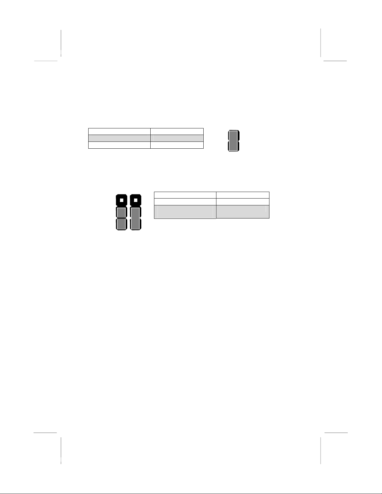
JP2: Keyboard power on jumper
Use this 3-pin jumper to enable keyboard power on with hot keys or
password.
3
2
1
Function Jumper Cap
Disable keyboard power on Short pins 1-2
Enable keyboard power on Short pins 2-3
JP2
JP4: Select Slot1 or Socket-370 jumper
Use this jumper to select if you are installing a processor into the Slot1 or
a processor into the socket-370.
Function Jumper Cap
Select Slot1 Short Pins 1-2
Select socket-370 Short pins 2-3
JP4 1 2 3
8

JP5: Clear CMOS memory jumper
Use this 3-pin jumper to clear all the current data stored in the CMOS
memory.
Function Jumper Cap
Normal operation Short pins 1-2
Clear CMOS Short pins 2-3
1
2
3
JP5
JP6: Select System bus frequency jumper
When this jumper is open, it forces the mainboard to use a 100 MHz
system bus, even if the processor requires a 66 MHz bus.
Function Jumper Cap
Auto Short pins 1-2
Force 100 MHz Open pins 1-2
JP6 1
2
JP7: Select FC-PGA Coppermine jumper
Use these 3-pin jumper sets to set the socket-370 on the board for use
with a FC-PGA Coppermine processor.
Function Jumper Cap
FC-PGA Coppermine Short pins 1-2
Normal operation
(other processors)
Short pins 2-3
JP7
1
2
3
9

Before You Begin
Before you begin to install your KOB 693 DCS mainboard, take some
precautions to ensure that you avoid the possibility of damage to the
product from static electricity. Ensure too that you are installing the
mainboard into a suitable case.
Static Electricity
In adverse conditions, static electricity can accumulate and discharge
through the integrated circuits and silicon chips on this product. These
circuits and chips are sensitive and can be permanently damaged by
static discharge.
♦ If possible wear a grounding wrist strap clipped to a safely
grounded device during the installation.
♦ If you don’t have a wrist strap, discharge any static by touching
the metal case of a safely grounded device before beginning the
installation.
♦ Leave all components inside their static-proof bags until they are
required for the installation procedure.
♦ Handle all circuit boards and electronic components carefully.
Hold boards by the edges only. Do not flex or stress circuit
boards.
Choosing a Case
This is a baby-AT sized mainboard that measures 220mm x 220mm. It
has 3 PCI slots, one ISA slot and an AGP slot. The mainboard has
connectors for either an ATX or an AT power supply so it can be
installed in almost all computer cases. Some features on the mainboard
are implemented by cabling connectors on the mainboard to indicators
and switches on the system case. Ensure that your case supports all the
features required. The KOB 693 DCS mainboard can support one or two
floppy diskette drives and four enhanced IDE drives. Ensure that your
case has sufficient power and space for all the drives that you intend to
install.
10
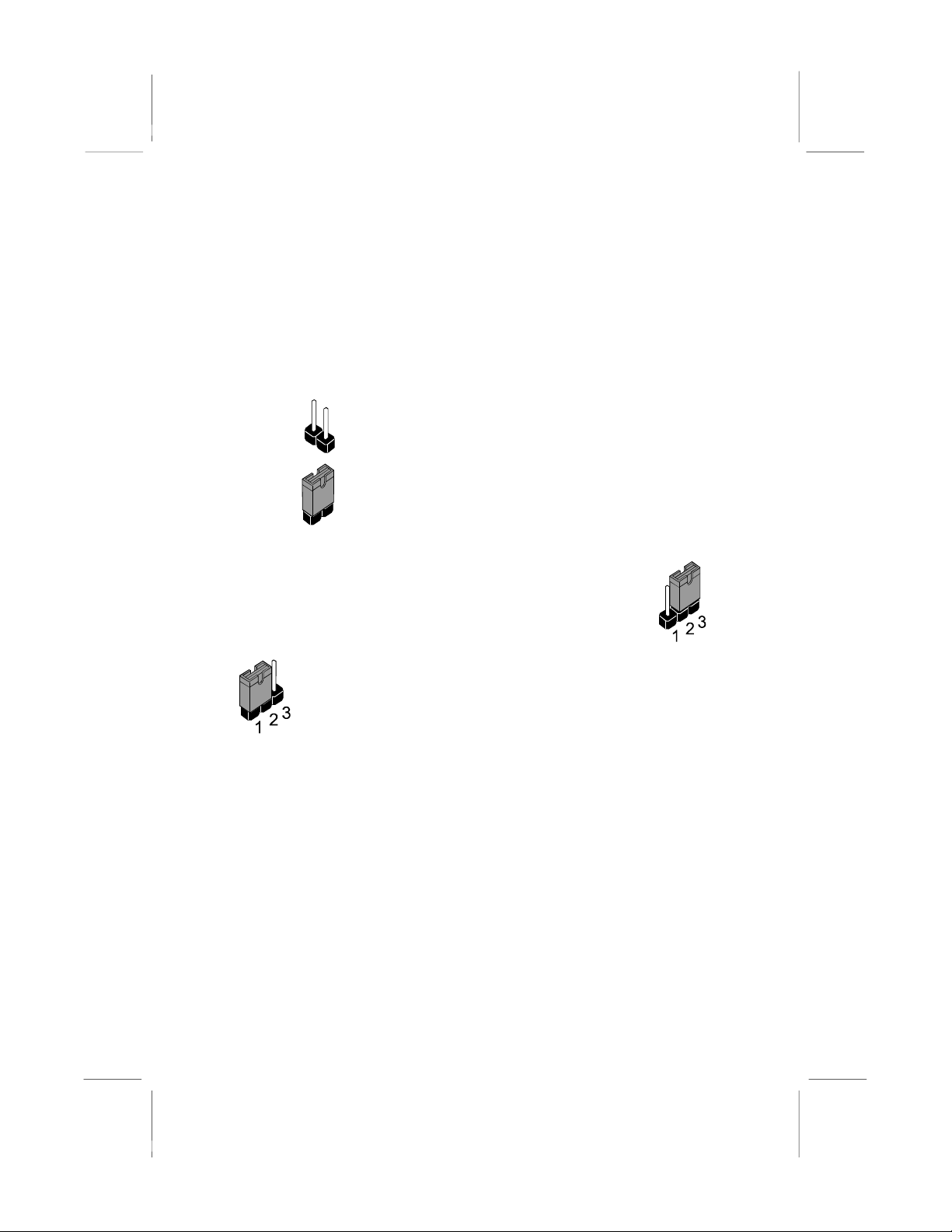
How to Set Jumpers
A jumper consists of two or more pins mounted on the mainboard. Some
jumpers might be arranged in a series with each pair of pins numbered
differently. Jumpers are used to change the electronic circuits on the
mainboard. When a jumper cap is placed on two jumper pins, the pins
are SHORT. If the jumper cap is removed (or placed on just a single pin)
the pins are OPEN.
OPEN This illustration shows a 2-pin jumper. When the
jumper cap is placed on both pins, the jumper is
SHORT. If you remove the jumper cap, or place the
jumper cap on just one pin, the jumper is OPEN.
SHORT
This illustration shows a 3-pin jumper. The jumper cap is
placed on pins 2 and 3, so this jumper setting is SHORT
PINS 2-3.
This illustration shows the same 3-pin jumper. The jumper
cap is placed on pins 1 and 2, so this jumper setting is
SHORT PINS 1-2.
In this manual, all the jumper illustrations clearly show the pin numbers.
When you are setting the jumpers, make sure that the jumper caps are
placed on the correct pins to select the function or feature that you want
to enable or disable.
11

Preparing the Mainboard
Mainboard Guide
Use the following illustration and key to identify the components on your
mainboard.
KBD
JP2
PW1
PW2
SLOT1 JP4
DIMM1
DIMM2
DIMM3
IDE2
IDE1 JP5
FAN2
J10
SOCKET-370
ISA
PCI3
PCI2
PCI1
A
GP
JP1B
JP1A
J3
SB1
J6
CD1
CD2
FAN1
J7
PRN1
J4
COM1
COM2
J1
JP6
JP7
FDC1
12

Key to Mainboard Components
Component Description
Slot1 Slot for Slot1 processor cartridge
Socket-370 Socket for PPGA Celeron Processor
AGP Slot for AGP graphics adapter
PCI 1,2,3 Three 32-bit PCI slots
ISA One 8/16-bit ISA slot
DIMM 1, 2, 3 Three slots for 168-pin SDRAM memory modules
FDC1 Connector for floppy disk drives
IDE1, IDE2 Primary and secondary IDE channels
PW1 Connector for ATX power supply
PW2 Connector for AT power supply
COM1 Connector for serial port 1/3
COM2 Connector for serial port 2/4
KBD Connector for AT keyboard
PRN1 Connector for parallel port LPT1
CD1 Audio connector for CD-ROM/DVD drive
CD2 Auxiliary audio connector for CD-ROM/DVD drive
FAN1 Power connector for CPU cooling fan
FAN2 Power connector for case cooling fan
SB1 SB-link connector for Creative PCI sound cards
J1 SPDIF digital audio connector
J3 Connector for fax/modem module
J4 Connector for audio ports extension bracket
J6 Wake on LAN connector
J7 Connector for ATX form card
(IR / PS/2 mouse / 2 x USB)
J10 Panel connector for case switches and indicators
JP1A Enable/disable onboard audio jumper
JP1B Enable/disable onboard fax/modem jumper
JP2 Keyboard power on jumper
JP4 Select Slot1 or Socket-370 jumper
JP5 Clear CMOS memory jumper
JP6 Select system bus frequency jumper
JP7 Select FC-PGA Coppermine processor jumper
13
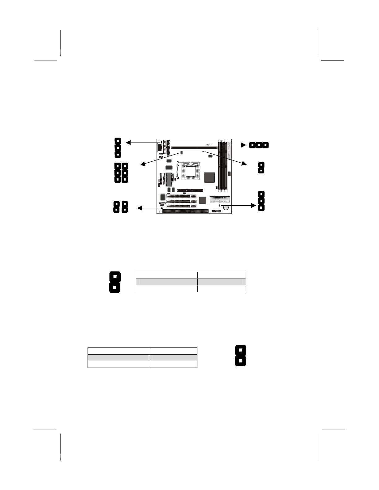
Check the Jumper Settings
Check all the mainboard jumpers to ensure that the board is configured
correctly.
JP5
JP4
JP6
B
JP1
JP2
JP7
A
JP1A: Audio Enable/disable Jumper
Use this 2-pin jumper to enable or disable the audio system integrated
on this mainboard. You have to disable the audio system if you plan on
using an alternate audio system on an add-in card.
1
2
JP1A
Function Jumper Cap
Enable audio Open pins 1-2
Disable audio Short pins 1-2
JP1B: Modem Enable/disable Jumper
Use this 2-pin jumper to enable or disable the modem integrated on this
mainboard. You have to disable the modem if you plan on using an
alternate modem.
1
2
JP1B
Function Jumper Cap
Enable modem Open pins 1-2
Disable modem Short pins 1-2
Note: When jumper JP1A is set to Disable Audio (short pins 1-2)
the integrated modem is also disabled, even if the jumper JP1B is
at the Enable Modem setting.
14
JP2: Keyboard Power On Jumper
This jumper lets you use a typed-in password as a power switch to turn
your system on. If you enable this property, you need to define the
password or the hot keys using the setup utility. See Chapter 3.
Function Jumper Cap
Disable keyboard power on Short pins 1-2
Enable keyboard power on Short pins 2-3
1
2
3
JP2
Note: The keyboard power on function may not function if you are
running this mainboard with an AT power supply.
JP4: Select Slot1 or Socket-370 Processor Jumper
Use this 3-pin jumper to prepare the mainboard for the installation of a
slot1 processor cartridge or a socket-370 PPGA Celeron processor.
1 2 3
JP4 Function Jumper Cap
Select slot1 processor Short pins 1-2
Select socket-370 processor Short pins 2-3
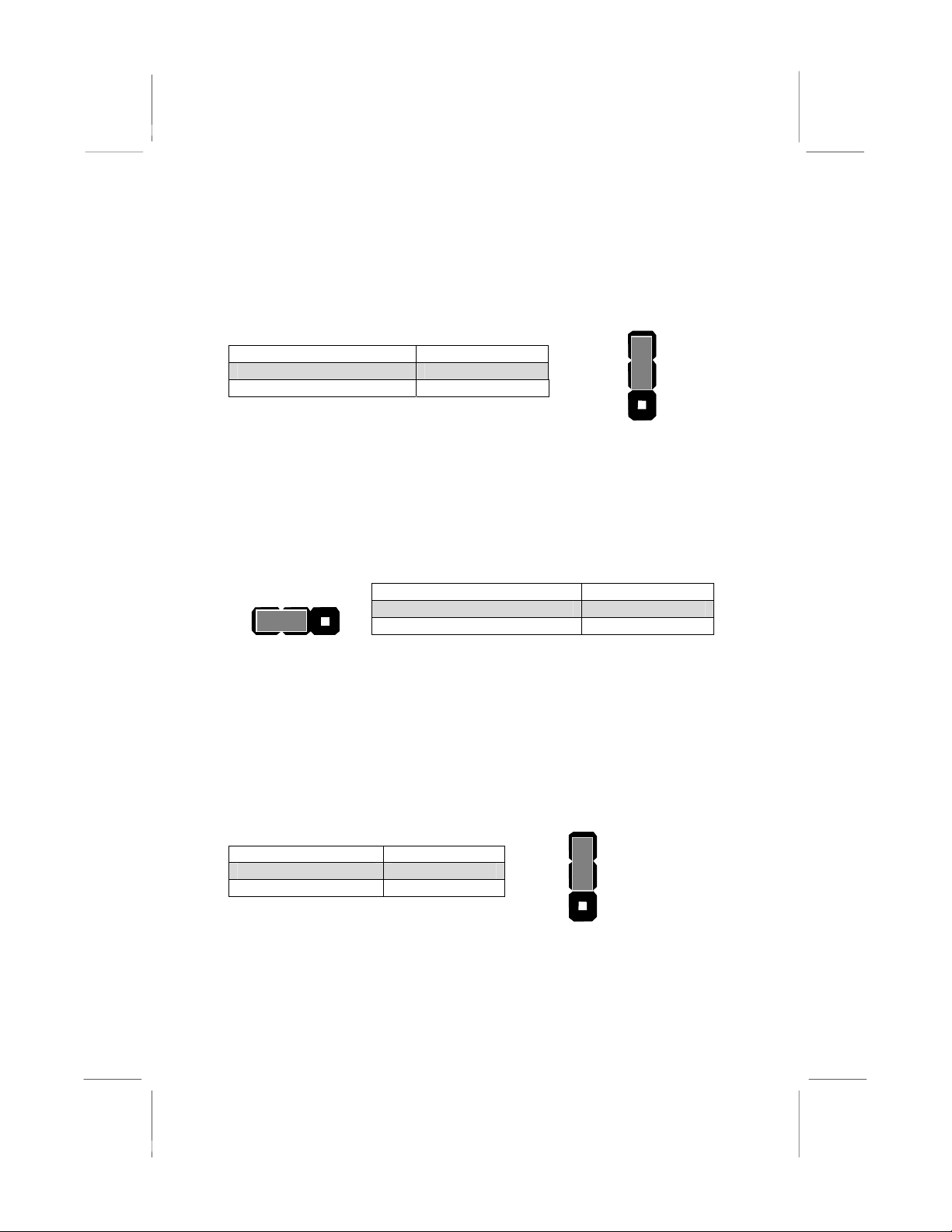
JP5: Clear CMOS Memory Jumper
This jumper lets you erase the system setup settings that are stored in
CMOS memory. You might need to erase this data if incorrect settings
are preventing your system from operating. To clear the CMOS memory,
turn off the system, disconnect the power cable from the mainboard, and
short the appropriate pins for a few seconds.
Function Jumper Cap
Normal Operation Short pins 1-2
Clear CMOS Short pins 2-3
1
2
3
JP5
15
JP6: Select System Bus Frequency Jumper
When this jumper is open, it forces the mainboard to use a 100 MHz
system bus, even if the processor requires a 66 MHz bus.
1
2
JP6
Function Jumper Cap
Auto Short pins 1-2
Force 100 MHz Open pins 2-3
JP7: Select FC-PGA Coppermine jumper
Use these 3-pin jumper sets to set the socket-370 on the board for use
with a FC-PGA Coppermine processor.
Function Jumper Cap
FC-PGA Coppermine Short pins 1-2
Normal operation
(other processors)
Short pins 2-3
1
2
3
JP7
16

Install the Mainboard in the Case
The mainboard is drilled with a series of holes. Most system cases have
mounting brackets installed in the case which correspond to the holes in
the mainboard. You can secure the mainboard in the system case by
placing the mainboard over the mounting brackets and driving screws
through the mainboard into the mounting brackets.
Note: Do not overtighten the screws as this can stress the
mainboard.
The illustration below shows a mainboard installing in a standard
desktop case.
Power Supply
Unit Drive
Cage
Expansion
Slots
I/O
Template
17
Table of contents
Other ECS Motherboard manuals


Popular Motherboard manuals by other brands


Midas
Midas RTE-V830-PC user manual

Wavelength Electronics
Wavelength Electronics WTC3243 DATASHEET AND OPERATING GUIDE

Texas Instruments
Texas Instruments DS90UB960-Q1EVM user guide

Portwell
Portwell ROBO-8913VG2AR user manual

Gigabyte
Gigabyte GA-HA65M-D2H-B3 user manual

ASROCK
ASROCK Fatal1ty Z77 Professional user manual


