ECS P5SJ-A User manual

P5SJ-A Mainboard
User’s Manual

P5SJ-A User’s Manual
Table Of Contents–II
Version 2.2
Copyright © October 1997 All rights reserved
This publication may not be copied, reproduced, translated, transmitted or reduced to
any printed or electronic medium or to any machine readable form, or stored in a retrieval
system, either in whole or in part without the written consent of the copyright holders.
The contents of this publication are subject to change. The manufacturer reserves the
right to alter the contents of this publication at any time and without notice. The contents of
this publication may contain inaccuracies or typographical errors and is supplied for infor-
mational use only.
Products are noted in this publication for identification purposes only. Microsoft is a
registered trademark and Windows is a trademark of Microsoft Corporation. Pentium is a
trademark of Intel Corporation. All other product names or brands may be trademarks or
registered trademarks of their respective holders.
FCC & DOC ComplianceFCC & DOC Compliance
FCC & DOC ComplianceFCC & DOC Compliance
FCC & DOC Compliance
Federal Communications Commission StatementFederal Communications Commission Statement
Federal Communications Commission StatementFederal Communications Commission Statement
Federal Communications Commission Statement
This device complies with FCC Rules Part 15. Operation is subject to the following two
conditions:
• This device may not cause harmful interference, and
• This device must accept any interference received, including interference that may cause
undesired operation.
This equipment has been tested and found to comply with the limits for a Class B digital
device, pursuant to Part 15 of the FCC Rules. These limits are designed to provide reasonable
protection against harmful interference in a residential installation. This equipment gener-
ates, uses and can radiate radio frequency energy and, if not installed and used in accordance
with the manufacturer’s instructions, may cause harmful interference to radio communica-
tions. However, there is no guarantee that interference will not occur in a particular installa-
tion.Ifthisequipmentdoescauseharmfulinterferenceto radio or television reception, which
can be determined by turning the equipment off and on, the user is encouraged to try to
correct the interference by one or more of the following measures:
• Re-orient or relocate the receiving antenna.
• Increase the separation between the equipment and the receiver.
• Connect the equipment to an outlet on a circuit different from that to which the receiver
is connected.
• Consult the dealer or an experienced radio/TV technician for help.
WW
WW
Warar
arar
arning!ning!
ning!ning!
ning! The use of shielded cables for the connection of the monitor to the graphics
card is required to assure compliance with FCC regulations. Changes or modifications to this
unit not expressly approved by the party responsible for compliance could void the user’s
authority to operate this equipment.
Canadian DeparCanadian Depar
Canadian DeparCanadian Depar
Canadian Department of Communications Statementtment of Communications Statement
tment of Communications Statementtment of Communications Statement
tment of Communications Statement
This digital apparatus does not exceed the Class B limits for radio noise emissions from
digital apparatus set out in the Radio Interference Regulations of the Canadian Department
of Communications.

P5SJ-A User’s Manual
Table Of Contents – III
1: P5SJ-A Package & Product Information............. 1.1
About This Manual....................................................................... 1.1
Package Contents............................................................... 1.3
Mainboard Features ........................................................... 1.4
Component Information ..................................................... 1.6
Expansion Cards & Slots.............................................................. 1.6
Memory Sockets & Modules ....................................................... 1.7
CPU Socket & CPU ....................................................................... 1.7
Port & Controller Connections ..................................................... 1.7
2: Using Your Mainboard ....................................... 2.1
System Controls.................................................................. 2.1
Hardware Controls & Indicators ................................................. 2.1
CMOS Setup Utility Controls......................................................... 2.3
Hardware Features............................................................. 2.6
Onboard Ports.............................................................................. 2.6
Connectors ................................................................................... 2.6
Optional Hardware...................................................................... 2.8
Firmware & Software.......................................................... 2.9
How To Use The CMOS Setup Utility............................................ 2.9
Clearing CMOS............................................................................. 2.9
Flashing The BIOS......................................................................... 2.11
Bus Master Drivers....................................................................... 2.11
Video Drivers ................................................................................ 2.11
Disabling Onboard Video Display Card...................................... 2.11
3: Reconfiguring Your Mainboard .......................... 3.1
Installing Expansion Cards .................................................. 3.1
ISA Cards & Slots.......................................................................... 3.1
Configuring Expansion Card Resources In CMOS Setup............ 3.2
Adding System Memory ..................................................... 3.5
Memory Configurations............................................................... 3.6

P5SJ-A User’s Manual
Table Of Contents–IV
Installing A CPU Upgrade ................................................... 3.9
The Basic Procedure .................................................................... 3.9
Configuring External Clock Speed & Factor ................................ 3.10
Configuring CPU Voltage ............................................................. 3.10
CPU Jumper Tables & Illustrations .............................................. 3.12
Adding An IDE Peripheral.................................................... 3.16
IDE Transfer Modes ...................................................................... 3.16
Installing IDE Devices.................................................................... 3.18
Adjusting Display Memory.................................................. 3.19
4: P5SJ–A Reference Information.......................... 4.1
Using This Section............................................................... 4.1
Jumper Configuration Summary......................................... 4.3
Supported CPUs.................................................................. 4.10
Interpreting CPU Markings .......................................................... 4.11
System Memory Specifications........................................... 4.13
Memory Configurations............................................................... 4.13
CMOS Setup Utility Summary ............................................. 4.14
Using the CMOS Setup Utility....................................................... 4.14
Accessing The CMOS Setup Utility............................................... 4.14
Standard CMOS Setup ................................................................. 4.18
BIOS Features Setup..................................................................... 4.22
Chipset Features Setup................................................................ 4.27
Power Management Setup ......................................................... 4.29
PNP/PCI Configuration................................................................. 4.34

P5SJ-A User’s Manual
1: Package & Product Information – 1.1
1: P5SJ-A Package & Product Information
This manual contains all the information you’ll need to use
the P5SJ-A mainboard. Please take a moment to familiarize your-
self with the design and organization of the manual.
About This Manual
This manual is divided into four sections:
• Section 1: Package & Product Information
A brief overview of what comes in the mainboard package, its
basic features, layout and component information.
• Section 2: Using Your Mainboard
Information on mainboard features that you may make use of
in operating your computer.
• Section 3: Reconfiguring Your Mainboard
How to change or upgrade the mainboard configuration.
• Section 4: Reference Information
A summary of the mainboard’s settings and specifications.
In This Section:
About This Manual
Package Contents
Component Information

P5SJ-A User’s Manual
1: Package & Product Information – 1.2
The manual uses some icons to call your attention to impor-
tant information. The icons appear in the sidebar and represent
the following:
• Important information
• A recommendation or good idea
• A warning or bad idea
• Danger warning
Online Manual Format
If the support disk for your mainboard is a CD-ROM disc, a
copy of the printed manual may be stored on the disc in Adobe
Acrobat format. If so, it requires Adobe Acrobat Reader version
3.0 or later to view it. Acrobat Reader for Microsoft Windows95
may also be supplied on the Support Disk. If not, you can obtain
afreecopyoftheReadersoftwarefromtheAbobewebsitewhich
is currently at www.adobe.com as well as other locations.
If you have the online manual, you may want to install Acro-
bat Reader on your system hard disk. You can copy the manual
over as well so that the manual is readily available without hav-
ing to hunt up the Support Disk when you want to view it.
If you are unfamiliar with Acrobat Reader, please take a mo-
ment to view the Reader Online Guide which is available under
the Help menu when you run Reader.
C
D
G
N

P5SJ-A User’s Manual
1: Package & Product Information – 1.3
Package Contents
The P5SJ–A mainboard package contains the following items,
as noted in the Quick Installation Guide. We’ve listed them here
again for your convenience. Please inspect the package contents
and confirm that everything is there. If anything is missing or
damaged, call your vendor for instructions before proceeding.
The package includes:
• P5SJ–A Mainboard
• Cable Pack:
– 1 Floppy Controller Cable
– 1 IDE Controller Cable
– 1 VGA Port Bracket with attached cable (SIS 5598 model)
• Optional Hardware:
– External USB dual-port bracket
• Support CD:
– IDE Bus Master Drivers
– Display Drivers
The SIS VGA display comes with drivers for a wide range of
Operating Systems. These are organized in individual folders. In
each folder there is a “readme” file that explains how to install
the driver. Please locate the folder for the driver you need and
check this file.
P5SJ–A Models
There are two P5SJ–A main-
board models. One has an
onboard video display fea-
ture – SIS5598, the other –
SIS5582– does not. If you
have the model with the
onboard display feature, it
comes with an external VGA
portbracketwithanattached
cable that connects to the
mainboard. Other than this
feature, the two models are
the same.
GYou can tell which model you
have by looking at the big
green heat sink in the middle
of the board. The SIS chip
number is printed on it.

P5SJ-A User’s Manual
1: Package & Product Information – 1.4
Mainboard Features
This mainboard is a highly integrated Mini-ATX design that
incorporatesmanyfeaturesontheboard.Themainboardincludes
the following features:
• Socket 7 CPU socket supports Pentium and compatible CPUs
up to 266MHz
• SIS5598 or 5582 (non-VGA) single chip solution
• Super I/O chip
• Integrated SIS VGA display (optional)
– Uses system memory for display memory
– Display drivers for multiple Operating Systems
• 256KB or optional 512KB Pipeline Burst SRAM Level 2 cache
• 4 SIMM memory module sockets:
– SIMMs: 5V EDO or Fast Page DRAM
– SIMMs in two banks SIM1/2, SIM3/4
– Supports up to 256MB
• Onboard Connectors
– Primary & Secondary EIDE channels, Ultra DMA support
– Floppy disk drive connector for two drives
– Optional Infrared module connector
• External Ports
– Two USB ports on optional port bracket
– COM1 & COM2 serial ports, enhanced Parallel port
– PS/2 Mouse & Keyboard connectors
• Expansion Card Slots
– Four PCI 2.1–compliant PCI slots
– Three 16-bit ISA slots
P5SJ-A User’s Manual
1: Package & Product Information – 1.5
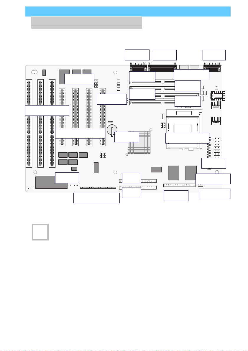
P5SJ-A Mainboard Layout
Jumper & Connectors
The illustration above shows
the connectors, sockets and
ports on the mainboard.
The VGA Port is a connector
for the external VGA port
bracket.
The USB Port is a connector
for the optional external dual
USB port bracket.
The IR Port is a connector for
an optional IrDA–compatible
infrared port module.
Socket 7
SiS
5598
Power
Floppy
IDE 1
IDE 2
COM2 COM1
Printer
KB/Mouse
CPU Socket 7
PCI Slots 4 3 2 1 Battery
SIMM4
ISA Slots 1 2 3
VGA Port
USB Port SIMM3
SIMM2 SIMM1
IR Port
Case Features
Fan Power
Wake Up
The model shown above
uses the SiS5598 chip with
heatsink and has the VGA
port connector and jumpers
onboard. The 5582 model
does not have these compo-
nents onboard.
G

P5SJ-A User’s Manual
1: Package & Product Information – 1.6
Component Information
This section is a brief description of the components on the
mainboard that you might need to know about if you want to
upgrade or change your system configuration. If your mainboard
is already installed in a system, it isn’t necessary for you to re-
view this section.
Thismainboardusesthe Mini-ATX‘formfactor’,adesign that
integrates many features onto the board including some number
of external ports.
Expansion Cards & Slots
The mainboard has seven expansion slots for system expan-
sion or ‘add-on’ cards. Three of them are ISA slots, the other four
arePCIslots.Whenyougetanexpansioncard,itmustuseoneof
these to connect to the computer.
The ISA expansion slots are a legacy of the original IBM PC/
ATdesign.Theyare16-bitslotsthat runatamoderate bus speed.
There are many kinds of expansion cards that use this slot design
to connect to the computer, some of the most common being
sound and modem cards.
PCI slots are the current high-speed 32-bit standard for sys-
tem expansion cards. They operate at a faster speed and have a
greater data throughput than ISA cards.
Expansion cards often make use of system resources, which
requiresmanagingthesystemresourceconfiguration.Mostnewer
expansion cards support the ‘Plug and Play’ standard that allows
an Operating System like Windows95 to automatically detect
them and configure system resources as needed. Some older ISA
designs may not support this standard and may therefore require
manual configuration. You should consult the specifications or
documentationforacardtodetermineifthisisthecaseandwhat
needs do be done to properly configure the card.

P5SJ-A User’s Manual
1: Package & Product Information – 1.7
Memory Sockets & Modules
There are four memory module sockets on the mainboard.
Theyuse72-pin SIMM memory modules. The socketsarepaired
into two ‘banks.’ This means you must install two modules at a
time. This mainboard has a very flexible memory design that al-
lows the use of a variety of memory options up to a total of
256MB. There is more information about this in ‘Adding System
Memory’ section of Section 3: Reconfiguring Your Mainboard.
CPU Socket & CPU
The Socket 7 CPU socket supports the full range of Pentium®-
class CPUs including MMX Pentiums®. Installing a CPU in the
socket is easy. The lever at the side of the socket latches the CPU
in place when it is down and releases it when raised.
If you want to install a CPU upgrade or are installing a CPU
on the board for the first time, please refer to ‘Installing a CPU’ in
Section 3: Reconfiguring Your Mainboard.
Port & Controller Connections
Thismainboardhastwo external Serial ports, one Parallel port
and a PS/2-type keyboard and mouse port built onto the board.
There are also several connectors built onto the board. There are
connectors for four IDE devices in two ‘channels’ and for two
floppy disk drives. There are also some connectors on the board
for some system case features and a CPU cooling fan.
Inaddition,thereisaconnectorforanoptionalexternaldouble
USB (Universal Serial Bus) port bracket that is an option for this
mainboard. If you have the version of this mainboard that has
the onboard video display card, there is also a connector for an
external VGA port bracket.
Details about these connectors are in Section 4: Reference In-
formation.

P5SJ-A User’s Manual
1: Package & Product Information – 1.8

P5SJ-A User’s Manual
2: UsingYour Mainboard– 2.1
2: Using Your Mainboard
This section covers the following topics:
• System Controls & Indicators
• Hardware Features
• Firmware & Software
Theygoover the system control featuresandstatus indicators
that derive from the mainboard and explain the software that
comes with or is built-into the mainboard
System Controls
There are two topics in this section, a explanation of the hard-
ware controls and status indicators that connect from the main-
board to your system case and some information about the parts
of the CMOS Setup Utility that allow you customize some sys-
tem features.
Hardware Controls & Indicators
Thereare somecontrolfeatures andstatusindicatorsthat con-
nect from the mainboard to your system case, which is some-
times called the ‘Enclosure’ or ‘Chassis.’ These are:
• Power Switch
• Power Status Indicator
• Suspend Switch
• Suspend Status Indicator
• Reset Switch
• Hard Disk Drive Activity Indicator
• Keyboard Lock
In This Section:
System Controls
Hardware Features
Firmware & Software

P5SJ-A User’s Manual
2: UsingYour Mainboard– 2.2
All of these case features connect to the mainboard via con-
nector strip J7. Not all system cases have all of these features, so
your system may not have all of them. The functions and op-
tions for these are shown in the table on the next page.
Hardware Controls & Indicators
Feature J7 Pins
Power Switch 19-20
Turns the system power on and off. In some systems, push once for
Suspend, push for >4 seconds for Off.
Power Status LED 1-3
When lighted indicates that system is turned on
Suspend Switch 4-5
Puts the system into Suspend state under Operating Systems that support
this power management feature
Suspend LED 6-8
When lighted indicates that system is suspended
Reset Switch 9-10
Pressing the Reset switch restarts the system
HDD Activity 17-18
Flashes when hard disk drive is active
Keyboard Lock 11-12
Disables keyboard via a lock mounted on front panel of the case

P5SJ-A User’s Manual
2: UsingYour Mainboard– 2.3
CMOS Setup Utility Controls
Two sections of the CMOS Setup Utility allow you to config-
ure how some of your system’s features work. These are:
• BIOS Features Setup
• Power Management Setup
The CMOS Setup Utility is a program that is permanently
stored in the BIOS chip on the mainboard. The utility creates a
system hardware configuration record that it stores in a small
amount of battery-supported memory on the board. The BIOS
uses this record to function as an interface between the system
hardware and the operating system. Most of the settings in the
CMOS Setup Utility are made automatically, so you won’t nor-
mally need to use this program. You can, however, customize
some of the operational features to suit how you prefer to use
the program.
Thescreen illustrations on the next two pagesshow the Setup
Default settings for these two sections of the utility.
The CMOS Setup Utility Summary in Section 4: Reference
Information, lists the setting options for each section of the util-
ity including the two noted above.

P5SJ-A User’s Manual
2: UsingYour Mainboard– 2.4
CMOS Setup Utility –
BIOS Features Setup
This section of the setup utility
allows you to configure some
system features including Vi-
rus Warning, Boot Sequence
and Security Option.
Virus Warning –
When enabled, monitors the
primary hard disk boot sector
and warns of any attempt to
write to it.
Boot Sequence –
Controls the order in which
thesystemchecksdiskdrives
for a boot disk.
Security Option –
Sets the level of password
protection for the system.

P5SJ-A User’s Manual
2: UsingYour Mainboard– 2.5
CMOS Setup Utility –
Power Management Setup
Thissectionofthesetuputility
allows you to configure the
powermanagementfeatures
supportedbytheBIOS.These
can also operate in tandem
withOperatingSystempower
management features.
YoucanusetheMinSavingor
MaxSavingdefaultmodes or
you can configure the power
management features indi-
vidually in the User Define
mode.

P5SJ-A User’s Manual
2: UsingYour Mainboard– 2.6
Hardware Features
This section is a brief overview of information about the
mainboard’s hardware features that connect to external devices.
Onboard Ports
Therearefiveexternal portsonthemainboard.Theseareports
standard to most personal computers:
• COM1 Serial Port
A high-speed serial port which can also be configured as the
COM3 port in the CMOS Setup Utility.
• COM2 Serial Port
A high-speed serial port which can also be configured as the
COM4 port in the CMOS Setup Utility.
• Parallel Port
The parallel port can be configured as a Standard, ECP or EPP
parallel port in the CMOS Setup Utility.
• PS/2 Keyboard Port
• PS/2 Mouse Port
Connectors
Thereare several connectors on the mainboard forconnecting
additional ports and internal peripheral devices
• IDE 1 – Primary IDE Channel
Connector for the Primary Master and Slave IDE devices.
• IDE 2 – Secondary IDE Channel
Connector for the Secondary Master and Slave IDE devices.
• Floppy Connector
Connector for two floppy disk drives.
P5SJ-A User’s Manual
2: UsingYour Mainboard– 2.7
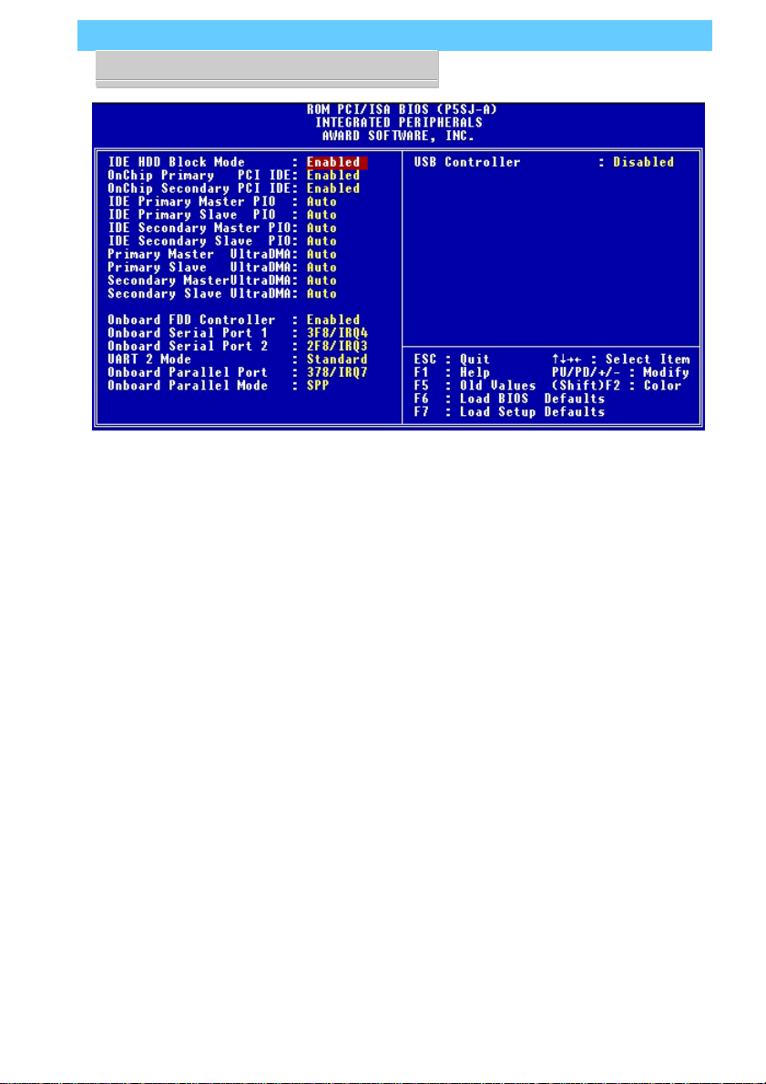
CMOS Setup Utility –
Integrated Peripherals
Thissectionofthesetuputility
configurestheIDEandFloppy
controllersandthesettingsfor
the external ports
Thissectionenablesandcon-
figures the optional USB and
Infrared features.
The screen illustration shows
the settings when the Opti-
mum Settings are loaded.

P5SJ-A User’s Manual
2: UsingYour Mainboard– 2.8
Optional Hardware
There two feature connectors on the mainboard for optional
ports. These require optional external port hardware.
USB Ports
The USB1 connector on the mainboard supports two Univer-
sal Serial Bus ports. An optional external port bracket attaches to
the onboard connector via an attached cable.
With the optional port bracket installed you can attach USB
devices to the external ports. If the USB ports are installed, the
USB Controller line in the Integrated Peripherals section of the
CMOS Setup utility must be set to ‘Enabled’. USB ports may
also require Operating System support for USB devices.
IR Port
The onboard IR connector supports an Infra-Red port module
that enables wireless communication between the computer and
other computers and devices with infrared capability.
The port module is an optional component. If it is installed,
you must set the UART 2 line in the Integrated Peripherals sec-
tion of the CMOS Setup utility to the appropriate IR mode used
by the module.
Table of contents
Other ECS Motherboard manuals


