ED 1480VA-60-201-900-SR User manual

BATH.EDBYELLEN.COM

ED is Ellen DeGeneres’ iconic style, values and personality shared through
collections of beautifully designed, high-quality products for home, pets and
people. All ED merchandise design and materials are approved by Ellen, ensuring
it maintains her standards and upholds her promise to make each item feel
like a personal connection between herself and consumers around the world.
INTRODUCTION
WELCOME

3
ATTACH YOUR RECEIPT HERE
Serial Number__________________ Purchase Date__________________
Questions, problems, missing parts? Before returning to your retailer, call our customer service
department at 1-855-571-1044, 9 a.m. - 5 p.m., EST, Monday - Friday.
ITEM #3629250; 3629251; 3629252; 3629253;
3629254; 3629255; 3629256; 3629257
MODEL #
1480VA-60-201-900-SR; 1480VA-60-201-900-UM;
1480VA-60-201-906-SR; 1480VA-60-201-906-UM;
1480VA-60-283-900-SR; 1480VA-60-283-900-UM;
1480VA-60-283-906-SR; 1480VA-60-283-906-UM
60-IN VANITY
WITH TOP
1480VA-60-201-900-SR ED 60-IN RIVEN WHITE VANITY W/ SEMI-RECESSED CARRARA MARBLE TOP
1480VA-60-201-900-UM ED 60-IN RIVEN WHITE VANITY W/ CARRARA MARBLE TOP
1480VA-60-201-906-SR ED 60-IN RIVEN WHITE VANITY W/ SEMI-RECESSED ENGINEERED GRAY TOP
1480VA-60-201-906-UM ED 60-IN RIVEN WHITE VANITY W/ ENGINEERED GRAY TOP
1480VA-60-283-900-SR ED 60-IN RIVEN COASTAL OAK VANITY W/ SEMI-RECESSED CARRARA MARBLE TOP
1480VA-60-283-900-UM ED 60-IN RIVEN COASTAL OAK VANITY W/ CARRARA MARBLE TOP
1480VA-60-283-906-SR ED 60-IN RIVEN COASTAL OAK VANITY W/ SEMI-RECESSED ENGINEERED GRAY TOP
1480VA-60-283-906-UM ED 60-IN RIVEN COASTAL OAK VANITY W/ ENGINEERED GRAY TOP
MODEL NUMBER DESCRIPTION
OR
OPTION 1
(Semi-Recessed Sink)
OPTION 2
(Undermount Sink)

4
Package Contents...........................................................................................................................5
Hardware Contents..........................................................................................................................5
Safety Instructions...........................................................................................................................5
Preparation ....................................................................................................................................6
Assembly or Installation Instructions .............................................................................................6
Care and Maintenance .................................................................................................................12
Warranty ......................................................................................................................................12
Replacement Parts List ...............................................................................................................13
Package Contents.........................................................................................................................15
Hardware Contents........................................................................................................................15
Safety Instructions.........................................................................................................................15
Preparation ..................................................................................................................................16
Assembly or Installation Instructions ...........................................................................................16
Care and Maintenance .................................................................................................................22
Warranty ......................................................................................................................................22
Replacement Parts List ...............................................................................................................23
TABLE OF CONTENTS FOR OPTION 1 (Semi-Recessed Sink)
TABLE OF CONTENTS FOR OPTION 2 (Undermount Sink)

5
HARDWARE CONTENTS (NOT SHOWN ACTUAL SIZE)
PACKAGE CONTENTS (Semi-Recessed Sink)
SAFETY INSTRUCTIONS
Please read and understand this entire manual before attempting to assemble, operate or install the
product.
WARNING
• There are several assembly steps, including unpacking, that require two adults.
CAUTION
• Follow these instructions closely, take your time, and use care while assembling this vanity.
KEEP THESE INSTRUCTIONS FOR FUTURE REFERENCE.
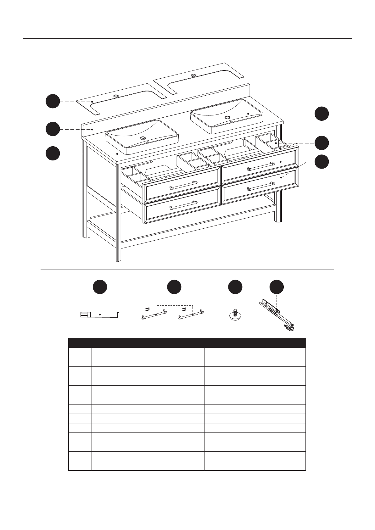
PART DESCRIPTION QUANTITY
A Vanity 1
B Top 1
C Backsplash 1
D Sink 2
E Drawer Divider 8
F
Upper Drawer
(preassembled
to Vanity (A))
2
G
Lower Drawer
(preassembled
to Vanity (A))
2
CARTON
Box 2 of 3
Box 2 of 3
Box 1 of 3
J Sink Template 2 Box 1 of 3
Box 3 of 3
A
E E E E
E E E E
F
G
F
G
B
D
D
C
Sink Template
J
Sink Template
J
AA
Touch Up Pen
Qty. 1
Handle (2 Options)
Brushed Nickel (Qty. 4)
Champagne Brass (Qty. 4)
BB

6
INSTALLATION INSTRUCTIONS (Semi-Recessed Sink)
PREPARATION
Before beginning assembly of product, make sure all parts are present. Compare parts with
package contents list and hardware contents list. If any part is missing or damaged, do not attempt
to assemble the product.
Estimated Installation Time: 40 minutes (24 hours for silicone caulk to dry).
Tools Required for Installation (not included): Phillips screwdriver, utility knife or scissors, silicone
caulk, power drill with drill bit, measuring tape, level
WARNING
Vanity (A) MUST be secured to wall.
Note: Clean area where the vanity (A) will be
permanently located prior to beginning installation,
ensuring the vanity (A) will not interfere with any
water supply and drain lines once mounted.
2. With two people, carefully place vanity (A)
against the wall in its final location.
While holding the vanity base firmly against the
wall, use the pre-assembled levelers on the
bottom of each leg of the vanity (A) to level the
item. Twisting the levelers counterclockwise
will raise the height of the vanity (A), and
twisting them clockwise will lower the vanity.
Once the vanity is in place, against the wall,
and level from front to back and side to side,
drill a hole through the vanity mounting area
and into the wall studs (as illustrated in
diagram 2). Using appropriate mounting
hardware (not included), secure the vanity (A) to
a wall stud. If possible, secure the vanity (A) to two wall studs for increased stability.
1. As shown in the diagram, fully extend the
drawer and locate the plastic levers on the
metal glide tracks. Push the left-side and
right-side levers at the same time to
disengage the drawer from the drawer glides.
Gently lift the drawer up to remove it from
vanity (A).
1
A
2
1
2
12
A

7
INSTALLATION INSTRUCTIONS (Semi-Recessed Sink)
3. Take out the top (B) and backsplash (C)
according to the steps indicated by the
drawings on the right, and place them face
up onto a scratch free surface such as a
foam sheet that came in the packaging.
Note: A
t this stage it may be easier to install
the faucet and drain kit (not included) to top (B)
per the manufacturer’s instructions, before
moving on to Step 4.
4.
Apply stain free silicone caulk (not included) to
the top edge of vanity (A). With the help of
another adult, gently lower top (B) onto the
vanity (A). Wipe away any excess caulk with a
soft cloth, and wait approximately 24 hours for
it to dry.
3
Remove the top foam sheet
C
Foam sheet
C
Remove the backsplash and place
it on a scratch free surface
Remove the foam sheet
B
4
1
2
2
A
B

8
INSTALLATION INSTRUCTIONS (Semi-Recessed Sink)
5. Put the sink template (J) on the top (B).
The holes in the cardboard needs to be
aligned with the hole in the stone top.
Make sure the sink template and stone top are
flush along the back edge.
Repeat for the remaining sink template.
6. Apply a thin bead of silicone caulk (not included)
onto the stone top close to the edge of the sink
cut out as pictured.
Repeat for the remaining stone top.
5
Sink Template
J
Sink Template
J
B
6
J
Sink Template
J
Sink Template
B

9
INSTALLATION INSTRUCTIONS (Semi-Recessed Sink)
8. Apply silicone caulk (not included) to unpolished
side and bottom of backsplash (C). Position
backsplash (C) on top (B) and against wall.
Clean any excess caulk before allowing
to dry.
7. With the help of another adult, Gently lower
the sink onto the stone top using even
pressure to set the sink properly.
Make sure the sink over-flow hole is at the
front of wood cabinet.
If some silicone caulk has over-flowed please
clean it up at that time with water.
Repeat for the remaining sink.
7
B
D
D
Sink Template Sink Template
8
1
22
C
B
10
INSTALLATION INSTRUCTIONS (Semi-Recessed Sink)
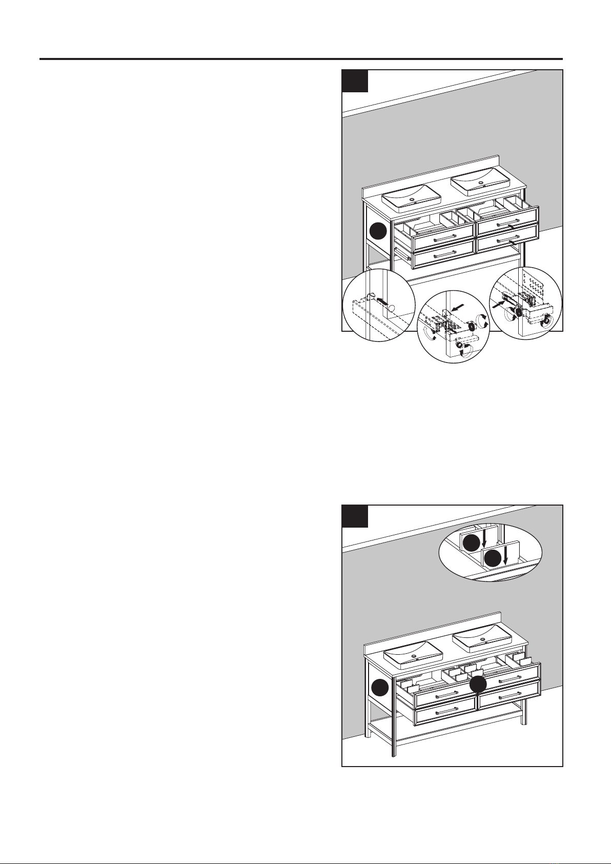
9. To reinstall drawer(s) into vanity (A), fully
extend metal glide tracks. Gently lower and
slide drawer box into rear glide catch. Next,
lower drawer box down to completely rest
on extended glides. Then, push plastic levers
to lock the drawer box in place.
Note: Drawer box alignment can be adjusted,
if necessary. As shown in the diagram, spin
the adjustment wheel to the left to raise the
drawer box, or to the right to lower the drawer
box. The left and right-side glide heights can
also be adjusted independently in order to find
the drawers best alignment position.
CAUTION
DO NOT force drawer or damage to glide(s) may
occur. If drawer does not slide in with ease,
remove and try again from the start.
10. Insert the four drawer dividers (E) into the
notch on the left and right sides of the inside
of the upper drawer (F).
9
A
1
2
3
10
E
E
AF

11
INSTALLATION INSTRUCTIONS (Semi-Recessed Sink)
BB
Hardware Used
Handle x 4
Assembly is now complete. Install desired
faucet and drain assemblies (neither included)
per the manufacturers’ instructions to complete
the installation.
11. One set of handles (BB) are attached to the
drawers (F & G), and the other set is packaged
separately in the box. If you would like to switch
handles, simply remove the existing handles
and attach the other finish, as illustrated in the
diagram.
Note: This vanity base comes with two
different drawer handle options. 11
12
BB
AF
G

12
CARE AND MAINTENANCE
WARRANTY
IMPORTANT
• Dust the vanity regularly with a soft, non-lint producing cloth or household dusting product.
• You can clean the vanity with a gentle, non-abrasive household cleaner.
• Make sure to dry the wood immediately with a soft cloth or towel.
• The stone top can be cleaned using standard marble cleaning agents available at your local
supplier.
• Tips for using touch-up pen (AA): For scratches, stroke in direction of scratch; for worn areas,
stroke in direction of wood grain. Rub off excess colorant promptly with a soft cloth.
• Shade variations and patterns are an inherent characteristic of stone (e.g. granite, marble,
engineered stone). Stone tops will vary from product to product. Use caution placing items
such as soap or any fragranced material on the stone surface. Use a soap dish, coaster or
similar item to protect the surface if placing any soap or fragranced products on the stone.
• If soap or fragranced products come in contact with the stone top, rinse the surface with water
and dry using a soft non-abrasive cloth.
• WARNING: Must use cleaning agents safe for stone. Check your cleaning agents use
restrictions before using on any stone. Damage to the stone may result. Vanity Manufacturer not
responsible for damage caused by improper cleaning agents or soaps used. Warranty will not
cover damage caused by the use of improper soaps or cleaning agents.
• DO NOT use products to clean the stone top that contain acetone, lemon, vinegar or other
acids as these may cause damage to the stone surface.
• Periodically reseal the stone top using an appropriate stone sealer available from your local
home store. Follow the manufacturer’s directions on how to apply.
The manufacturer warrants this item against defects in materials and workmanship for a period of
one (1) year from the date of original retail purchase. This warranty applies only to the original
purchaser. This warranty does not apply to any damage on the product by accident, misuse, or
modified, improper installation or by affixing accessories not produced by the manufacturer. The
manufacturer will not be held liable for damages caused from cleaners or soaps that etch or stain
the stone top. The manufacturer is not accountable whatsoever for product installation during the
warranty period. There is no further expressed warranty. The manufacturer shall not be legally
responsible for incidental, consequential or special damages arising at or in connection with
product use or performance except as may otherwise be accorded by law. The manufacturer
disclaims any and all implied warranties.
13
REPLACEMENT PARTS LIST FOR 1480VB-60-201-SR (Semi-Recessed Sink)
PART DESCRIPTION PART #
E Drawer Divider 1480VB-60-201-DIVIDER
D Sink SN047B
C60" Dark Gray Backsplash PUBS-25-906-60
60" Carrara Marble Backsplash PUBS-25-900-60
BComplete Set 60" Dark Gray Top 3550VT-60-906
Complete Set 60" Carrara Marble Top 3550VT-60-900
J Sink Template SN047B-TEMPLATE
H Drawer Front 1480VB-60-201-DRAWER FRONT
AA Touch-up Pen OF-0010
BB Handle-brushed nickel 1480-BN HARDWARE
Handle-champagne brass 1480-CB HARDWARE
CC Leveler T-1007
DD 16-IN Glide Track Set SH-ABC-16IN-3A
For replacement parts, call our customer service department at 1-855-571-1044, 9 a.m. - 5 p.m.,
EST, Monday - Friday.
AA BB CC DD
Sink Template Sink Template
E
D
H
J
C
B

14
REPLACEMENT PARTS LIST FOR 1480VB-60-283-SR (Semi-Recessed Sink)
For replacement parts, call our customer service department at 1-855-571-1044, 9 a.m. - 5 p.m.,
EST, Monday - Friday.
PART DESCRIPTION PART #
E Drawer Divider 1480VB-60-283-DIVIDER
D Sink SN047B
C60" Dark Gray Backsplash PUBS-25-906-60
60" Carrara Marble Backsplash PUBS-25-900-60
BComplete Set 60" Dark Gray Top 3550VT-60-906
Complete Set 60" Carrara Marble Top 3550VT-60-900
J Sink Template SN047B-TEMPLATE
H Drawer Front 1480VB-60-283-DRAWER FRONT
AA Touch-up Pen M-1108
BB Handle-brushed nickel 1480-BN HARDWARE
Handle-champagne brass 1480-CB HARDWARE
CC Leveler T-1007
DD 16-IN Glide Track Set SH-ABC-16IN-3A
AA BB CC DD
Sink Template Sink Template
E
D
H
J
C
B

15
HARDWARE CONTENTS (NOT SHOWN ACTUAL SIZE)
PACKAGE CONTENTS (Undermount Sink)
SAFETY INSTRUCTIONS
Please read and understand this entire manual before attempting to assemble, operate or install the
product.
WARNING
• There are several assembly steps, including unpacking, that require two adults.
CAUTION
• Follow these instructions closely, take your time, and use care while assembling this vanity.
KEEP THESE INSTRUCTIONS FOR FUTURE REFERENCE.
PART DESCRIPTION QUANTITY
A Vanity 1
B Top 1
C Backsplash 1
D Sink 2
E Drawer Divider 8
F
Upper Drawer
(preassembled
to Vanity (A))
2
G
Lower Drawer
(preassembled
to Vanity (A))
2
CARTON
Box 2 of 3
Box 2 of 3
Box 1 of 3
Box 3 of 3
B
C
D
D
A
E E E E
E E E E
F
G
F
G
AA
Touch Up Pen
Qty. 1
Handle (2 Options)
Brushed Nickel (Qty. 4)
Champagne Brass (Qty. 4)
BB EE FF GG HH II
Lock Washer
Qty. 8
Nut
Qty. 8
Wrench
Qty. 1
Bolt
Qty. 8
Sink Bracket
Qty. 8

16
INSTALLATION INSTRUCTIONS (Undermount Sink)
PREPARATION
Before beginning assembly of product, make sure all parts are present. Compare parts with
package contents list and hardware contents list. If any part is missing or damaged, do not attempt
to assemble the product.
Estimated Installation Time: 40 minutes (24 hours for silicone caulk to dry).
Tools Required for Installation (not included): Phillips screwdriver, utility knife or scissors, silicone
caulk, power drill with drill bit, measuring tape, level
WARNING
Vanity (A) MUST be secured to wall.
Note: Clean area where the vanity (A) will be
permanently located prior to beginning installation,
ensuring the vanity (A) will not interfere with any
water supply and drain lines once mounted.
2. With two people, carefully place vanity (A)
against the wall in its final location.
While holding the vanity base firmly against the
wall, use the pre-assembled levelers on the
bottom of each leg of the vanity (A) to level the
item. Twisting the levelers counterclockwise
will raise the height of the vanity (A), and
twisting them clockwise will lower the vanity.
Once the vanity is in place, against the wall,
and level from front to back and side to side,
drill a hole through the vanity mounting area
and into the wall studs (as illustrated in
diagram 2). Using appropriate mounting
hardware (not included), secure the vanity (A) to
a wall stud. If possible, secure the vanity (A) to two wall studs for increased stability.
1. As shown in the diagram, fully extend the
drawer and locate the plastic levers on the
metal glide tracks. Push the left-side and
right-side levers at the same time to
disengage the drawer from the drawer glides.
Gently lift the drawer up to remove it from
vanity (A).
1
A
2
1
2
12
A

17
3. Take out the top (B) and backsplash (C)
according to the steps indicated by the
drawings on the right, and place them face
down onto a scratch free surface such as a
foam sheet that came in the packaging.
4. Apply silicone caulk (not included) to
the top edge of sink (D). With the help of
another adult, lower the sink onto the back
side of the stone top.
Make sure the sink over-flow hole is facing
the front of stone top.
Be sure to align the sink well with the stone top
cut out allowing for equal stone overhang on the
front, back and sides of the ceramic sink (D).
Repeat for the remaining sink.
Note: To install the sink onto the top correctly,
ensure that the two "BACK" stamps on the sink
and the top are aligned on the same sides.
Use the guide lines marked on the sink and
bottom side of stone top to assist with sink
location.
INSTALLATION INSTRUCTIONS (Undermount Sink)
3
Remove the top foam sheet
Remove the foam sheet
Remove the cutout foam
sheet & hardware
Remove the top and place it
on a scratch free surface
Remove the backsplash and place
it on a scratch free surface
C
Foam sheet
C
Foam sheet
B
BACK
FRONT
BACK
FRONT
B
BACK
FRONT
BACK
FRONT
1
2
1
2
B
BACK
FRONT
BACK
FRONT
Hardware
Pack
Hardware
Pack
4
BACK
1
2
2
2
2
BACK
BACK
BACK
BACK
D
D
B
Sink Lip
Top
BACK
BACK

18
INSTALLATION INSTRUCTIONS (Undermount Sink)
Hardware Used
Bolt x 8
5. Screw bolts (EE) into the threaded holes of
stone top (B)
Hardware Used
Sink bracket x 8
Nut x 8
x 8Lock Washer
6. Lower the sink brackets (FF) over the bolts
(EE) and allow to rest on the sink lip. Adjust
location of bracket to firmly grasp sink lip.
Lower lock washers (HH) over bolts (EE) and
secure with nuts (GG). Hand tighten nuts (GG)
with included wrench (II).
DO NOT OVER TIGHTEN!
Repeat for the remaining sink.
Tip: Check that the sink placement is well
centered front to back and side to side of the
stone top cut out before allowing the silicone
caulk to dry. If the sink is not centered well
unscrew sink clamps, re-adjust the sink position
and re-tighten the sink brackets.
EE
FF
GG
HH
Wrench x 1
II
5
EE
D
D
B
BACK
BACK
BACK
BACK
6
3
GG
HH
EE
II
2
FF
1
D
D
B
BACK
BACK
BACK
BACK

19
INSTALLATION INSTRUCTIONS (Undermount Sink)
8. Apply silicone caulk (not included) to unpolished
side and bottom of backsplash (C). Position
backsplash (C) on top (B) and against wall.
Clean any excess caulk before allowing
to dry.
7
1
2
2
A
B
8
1
22
C
B
7. To install the Top (B) to the vanity (A).
Apply silicone caulk to the top edge of the
wood cabinet. With the help of another adult,
gently lower the stone top with assembled sink
onto the cabinet. Make sure the stone top is flush
with the back side of the wood cabinet and the
stone overhang is equal on both sides over the
wood cabinet left and right side walls. Remove
any excess caulk before allowing to dry.
Helpful tip: it may be easier to install your
choice of faucet (not included) before securing
the vanity top (B) to vanity base (A).

20
INSTALLATION INSTRUCTIONS (Undermount Sink)
9. To reinstall drawer(s) into vanity (A), fully
extend metal glide tracks. Gently lower and
slide drawer box into rear glide catch. Next,
lower drawer box down to completely rest
on extended glides. Then, push plastic levers
to lock the drawer box in place.
Note: Drawer box alignment can be adjusted,
if necessary. As shown in the diagram, spin
the adjustment wheel to the left to raise the
drawer box, or to the right to lower the drawer
box. The left and right-side glide heights can
also be adjusted independently in order to find
the drawers best alignment position.
CAUTION
DO NOT force drawer or damage to glide(s) may
occur. If drawer does not slide in with ease,
remove and try again from the start.
10. Insert the four drawer dividers (E) into the
notch on the left and right sides of the inside
of the upper drawer (F).
9
A
1
2
3
10
E
E
AF
This manual suits for next models
15
Table of contents
Other ED Indoor Furnishing manuals

ED
ED 1656VB-30-241 User manual

ED
ED 1480VB-30-201 User manual

ED
ED 1549FC-24-201 User manual

ED
ED 1549WC-24-201 User manual

ED
ED 1656FC-24-241 User manual

ED
ED 1656VB-36-241 User manual

ED
ED 1549VB-30-201 User manual

ED
ED 1580WC-24-201 User manual

ED
ED 1580WC-24-201 User manual

ED
ED 1480FC-24-201 User manual


Popular Indoor Furnishing manuals by other brands

Regency
Regency LWMS3015 Assembly instructions

Furniture of America
Furniture of America CM7751C Assembly instructions

Safavieh Furniture
Safavieh Furniture Estella CNS5731 manual

PLACES OF STYLE
PLACES OF STYLE Ovalfuss Assembly instruction

Trasman
Trasman 1138 Bo1 Assembly manual

Costway
Costway JV10856 manual


