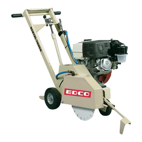
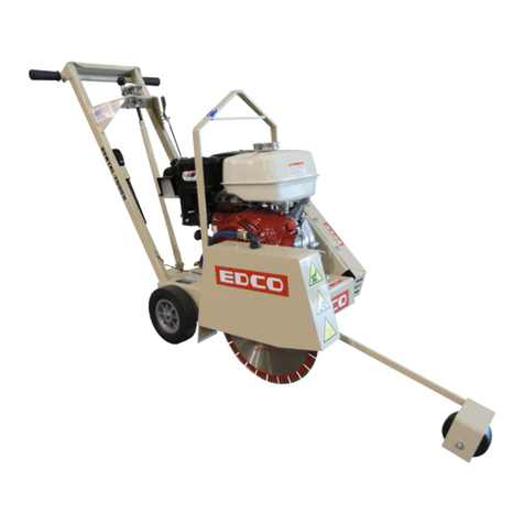
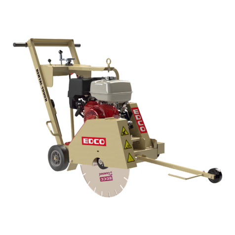
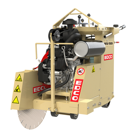
Edco KL-14 User manual

Page 1
Tool Rental Center
MANUAL
EDCO
KL-14
Reorder Part # HDTR-SEC-TM Class # 2985
39200HD-0917 Revised Starting Serial #: 171110122

Page 2
READ AND UNDERSTAND THE OPERATORS INSTRUCTION MANUAL THOROUGHLY
BEFORE ATTEMPTING TO OPERATE THIS EQUIPMENT.
Death or serious injury could occur if this machine is used improperly.
Extreme care must be taken when operating electric
models with water present: Ensure power cord is prop-
erly grounded, is attached to a Ground-Fault-Interrupter
(GFI) outlet, and is undamaged.
• Check all electrical cables - be sure connections are tight and
cable is continuous and in good condition. Be sure cable is
correctly rated for both the operating current and voltage of
this equipment.
• Improper connection of the equipment-grounding conductor can
result in a risk of electric shock. Check with qualied electri-
cian or service person if there is any doubt as to whether the
outlet is properly grounded. Adhere to all local codes and
ordinances.
• NOTE: In the event of a malfunction or breakdown, grounding
provides a path of least resistance for the electric current to
dissipate. The motor is equipped with a grounded plug and
must be connected to an outlet that is properly installed and
properly grounded. DO NOT modify the plug provided on the
motor. If the plug does not t the outlet have a qualied electri-
cian install the proper receptacle.
• Switch motor OFF before disconnecting power.
• Engine exhaust from this product contains
chemicals known to the State of California to cause
cancer, birth defects or other reproductive harm.
• Gasoline is extremely ammable and poison-
ous. It should only be dispensed in well ventilated
areas, and with a cool engine.
• Small gasoline engines produce high concentra-
tions of carbon monoxide (CO) example: a 5 HP 4
cycle engine operation in an enclosed 100,000
cu. ft. area with only one change of air per hour is capable of
providing deadly concentrations of CO in less than fteen min-
utes. Five changes of air in the same area will produce noxious
fumes in less than 30 minutes. Gasoline or propane powered
equipment should not be used in enclosed or partially enclosed
areas. Symptoms of CO poisoning include, headache,
nausea, weakness, dizziness, visual problems and loss of
consciousness. If symptoms occur get into fresh air and
seek medical attention immediately.
SAFETY
MESSAGES SAFETY MESSAGES
Indicates an imminent hazard which, if not
avoided, will result in death or serious injury.
Indicates an imminent hazard which, if not
avoided, can result in death or serious injury.
Indicates hazards which, if not avoided, could
result in serious injury and or damage to the
equipment.
• Safety Instructions are proceeded by a graphic alert symbol
of DANGER, WARNING, or CAUTION.
ELECTRICAL POWERED EQUIPMENT
GASOLINE/PROPANE POWERED EQUIPMENT
•Equipment should only be operated by trained personnel in
good physical condition and mental health (not fatigued). The
operator and maintenance personnel must be physically able
to handle the bulk weight and power of this equipment.
•This is a one person tool. Maintain a safe operating distance
to other personnel. It is the operators’ responsibility to keep
other people (workers, pedestrians, bystanders, etc.) away
during operation. Block o the work area in all directions with
roping, safety netting, etc. for a safe distance. Failure to do so
may result in others being injured by ying debris or exposing
them to harmful dust and noise.
•This equipment is intended for commercial use only.
•For the operator’s safety and the safety of others, always keep
all guards in place during operation.
•Never let equipment run unattended.
• Personal Protection Equipment and proper safety attire must
be worn when operating this machinery. The operator must
wear approved safety equipment appropriate for the job such
as hard hat and safety shoes when conditions require. Hear-
ing protection MUST be used (operational noise levels of this
equipment may exceed 85dBA). Eye protection MUST be worn
at all times.
Keep body parts and loose clothing away from moving
parts. Failure to do so could result in dismemberment
or death.
• Do not modify the machine.
• Stop motor/engine when adjusting or servicing this equipment.
Maintain a safe operating distance from ammable
materials. Sparks from the cutting-action of this machine
can ignite ammable materials or vapors.
GENERAL INSTRUCTIONS
DUST WARNING
Some dust created by power sanding, sawing,
grinding, drilling, and other construction activi-
ties contains chemicals known to cause cancer,
birth defects, or other reproductive harm. Some
examples of these chemicals are:
• Lead from lead-based paints, and
• Crystalline silica from bricks and concrete and other
masonry products.
Your risk of exposure to these chemicals varies depending
on how often you do this type of work. To reduce your risk:
work in a well ventilated area, use a dust control system, such
as an industrial-style vacuum, and wear approved personal
safety equipment, such as a dust/particle respirator designed
to lter out microscopic particles.
• Do not disconnect power by pulling cord. To disconnect, grasp
the plug, not the cord.
• Unplug power cord at the machine when not in use and before
servicing.

Page 3
TOOL RENTAL CENTER MANUAL
KL-14
TABLE OF CONTENTS
Section Page Number
Safety Messages and General Instructions.................................................................................. 2
How To Order Replacement Parts................................................................................................ 3
Operation Controls ....................................................................................................................... 4
Operating Instructions ...............................................................................................................5-6
Maintenance Instructions.............................................................................................................. 7
Changing Blade............................................................................................................................ 8
Lubrication Points......................................................................................................................... 9
Maintenance Schedule............................................................................................................... 10
Notes: ......................................................................................................................................... 11
Illustration 1: Main Grouping..................................................................................................12-13
Illustration 2: Arbor & Blade Guard Grouping ........................................................................14-15
Illustration 3: Engine & Belt Drive Grouping ..........................................................................16-17
Illustration 4: Wiring Diagram ..................................................................................................... 18
Decals......................................................................................................................................... 19
HOW TO ORDER REPLACEMENT PARTS
To insure product safety and reliability, always use
genuine EDCO replacement parts when making
repairs to the equipment.
When calling for parts, specify the MODEL and
SERIAL number of the machine, which can be found
on the NAME PLATE. Keep that information in the
space provided. In addition to this information, give
part number, description, and quantity as listed on
the parts list to your parts representative.
Please note: Due to improvements and changes
in the equipment, the illustrations shown may be
dierent than the actual machine.
FILL IN INFORMATION BELOW
Date of Purchase ______________________________
Model # _____________________________________
Serial # ______________________________________
SKU # ______________________________________

Page 4
OPERATING CONTROLS
MODEL KL-14 / 14” WALK BEHIND SAW
Collapsable Handle
Choke
Guide Bar
Throttle
Rope Pull
Handle Lock
Depth Control
Water Valve
On/O Switch
Please Note:
Controls shown are for the model indicated.
The location of these controls may vary on the dierent models.
Due to improvements and changes in the equipment, the illustration shown may be dierent from the actual machine.

Page 5
Possible Diamond Blade Problems
Segment Loss: Arbor Hole Cracked Segments Blade Will Not Cut:
Usually insucient Out-Of-Bound And or Core Blade is glazed or
water Blade not properly tightened Wrong Blade for job to hard for job
or seated on arbor
IMPORTANT NOTES
Operating Instructions
• Read and understand all operating instructions before operating this equipment.
Death or serious injury can result if this machine is used improperly.
• Concrete saws are designed to be used to cut at horizontal concrete or asphalt
slabs using diamond saw blades.
• The machines may be equipped with gasoline engines or electric motors.
• They are designed to be controlled by a single operator from a position at the rear of the saw.
• Maintain a safe distance from other personnel in the area.
Be sure to read the Rx for Concrete Saws supplied with your machine.
IMPORTANT: Perform Pre-Start Check.
• Visually inspect the equipment for wear or damage.
• Be sure all guards are in place and functioning properly. Do not operate unless blade guard is in place
and secure.
• Perform all daily maintenance.
• Check to be sure water tubes are functioning properly if performing wet-cutting operations.
• Inspect blade - Be sure the correct blade is installed properly on the machine, including RPM, size,
mounting arrangement and its intended use.
• Check blade for damage (see
Figure 1
, below).
• Inspect work area to determine the presence and location of deck inserts, pipes, columns and objects
protruding from the slab surface so that they may be avoided during the cutting operation. Scribe a
line to help guide the saw.
Figure 1

Page 6
Operating Instructions
•FOR WET CUTTING: Attach the water supply. A ow rate of approximately 2 gallons per minute
(minimum) is required. Attach the water hose to the coolant valve. Use the valve to control the
ow of water.
•FOR DRY CUTTING: Provide a respirator and dust control system.
•FOR GASOLINE MODELS: Put the engine stop switch and the machine stop switch in the “RUN”
position. Consult the engine manufacturers operating instructions and follow the directions for starting
and breaking in the engine.
•BEFORE STARTING THE ENGINE OR MOTOR: Raise the saw blade clear of the working surface.
The blade is raised using the depth control handwheel knob mounted on the lower handle assembly
(Figure 2)
.Lift the knob to unlock and turn the handwheel clockwise until the blade is clearly
o the ground.
•START ENGINE AND ALLOW IT TO REACH OPERATING SPEED: Position the saw over the cutting
line. Bring the engine to full speed. Lower the blade into the slab surface by slowly turning the depth
control handwheel knob. NOTE - the 14 inch blade has a maximum cutting depth of 4 3/4”. Do not
allow the arbor anges to contact slab surface.
When the selected cutting depth is reached, lock the depth control handwheel knob and proceed to
push the saw forward. The saw blade must remain straight, do not twist, and do not force blade, the
engine or motor should not strain when cutting.
•TO STOP THE MACHINE: Stop forward motion. Push the throttle to idle. Turn the depth control
handwheel knob clockwise to raise the blade clear of the cut. Turn ignition or power switch
o and let the engine come to a complete stop. Turn o the water supply.
•WHEN MANEUVERING THE SAW: Make sure the blade is raised high enough so it does not strike
the slab surface. Damage to blade may occur with inadvertent contact with the slab or other object.
•DO NOT FORCE BLADE WHILE CUTTING.
•IF THE POWER SOURCE STALLS IN THE CUT: Raise the blade completely out of the cut.
Disconnect the power source (i.e. the spark plug wire on a gasoline engine or disconnect an electric
model at the machine). Inspect the blade ange nut/bolt to verify that they are still tight, and inspect
the blade for damage. Replace damaged (or questionable) blades immediately.
•WHEN TRANSPORTING THE SAW: Be sure to remove the blade. Before removing the blade,
disconnect the power source before lifting or removing any guard. See the directions for Changing
Blades on
(page 8)
.
•WHEN STORING THE SAW: Loosen handle locks. Pull handle up and rotate forward.
Figure 2 Figure 3 Figure 4

Page 7
Maintenance Instructions
Disconnect the machine from the power source. Remove the spark plug lead on gasoline engine
models or disconnect the supply voltage connector on electric models, before performing any main-
tenance. All maintenance to be performed regularly by qualied personnel.
•Never work under saw without rst placing chocks on the wheels and support device under the saw to prevent
it from moving or falling. Always work on a at and level surface.
• Refer to the engine manual for maintenance information specic to the engine used. Be sure to check oil level
before operation. Clean air lter element daily.
• Grease bearings after every 4 hours of use. Refer to
(page 9)
for lubrication points on available models.
• Perform a visual inspection of the entire machine before operation. Be sure all fasteners are tight and secure,
check for signs of metal cracking or fatigue, inspect for damage to electrical wiring, damage to fuel lines, check
bearings and inspect to be sure proper guards are in place and secure, etc...
• Inspect belts before operation. Check belt tension. On new equipment, belts should be re-tensioned after the
rst four hours of use. Damaged, stretched or excessively worn belts should be replaced with a new matched set.
• To tension belts, loosen motor mounting hardware slightly. Either push motor towards the rear of the saw
(handle bar side) until the belts are tight or on the models with a belt tensioning adjustment bolt, use bolt to
adjust the engine until the belts are tight. Re-torque the engine mounting hardware.
• Proper belt tension must be maintained to transmit the engine power to the cutting blade. Slipping belts will
over-heat, the blade life will be shortened and the cutting speed limited. Over tensioned belts will shorten the
belt and bearing life.
• Check diamond blades for cracks, loose segments and oversize, worn, or out-of-round arbor holes
(See Figure 1)
. Do not use any questionable blade since serious injury and/or damage to property can result.
Do not use warped, twisted, or out-of-balance blades. Unbalanced blades will wear excessively, vibrate and
damage both arbor shaft and bearings. Do not use a blade without a drive pinhole
(Figure 5)
.
• For safety reasons, EDCO does not recommend the use of any abrasive blades. Abrasive blades can
break and cause serious personal injury to operator and/or bystanders. If abrasive blades are used by choice,
use only reinforced abrasive blades. Inspect abrasive blades carefully.
• Be sure arbor shaft, backing plate and blade cap are clean and in good
condition. Flanges should be free of nicks and burrs. Replace if out-of-round or worn.
Figure 9
Figure 5
Drive Pin Hole

Page 8
Changing Blades
Disconnect the machine from the power source before performing any work on the
equipment (i.e. changing the blade). To disconnect the power source on gasoline engine
models, remove the spark plug lead.
•Make sure you have the proper blade for the job. Determine the hardness and composition of the
slab. Give your dealer complete information including whether re-bars are present, the desired
depth of the cut, and the length of the cut. If in doubt, contact the blade manufacturer.
Inspect the blade before installing. Check diamond blades for cracks, loose segments
and oversize, worn, or out-of-round arbor holes. (Figure 1) Do not use any questionable
blade since serious personal injury and/or damage of property can result. Do not
use warped, twisted, or out-of-balance blades. Unbalanced blades will wear excessively, vibrate
and damage both arbor shaft and bearings. Do not use a blade without a drive pinhole (Figure 5).
For safety reasons, EDCO does not recommend the use of any abrasive blades. Abrasive
blades can break and cause serious personal injury to operator and/or bystandards. If
abrasive blades are used by choice, use only reinforced abrasive blades. Inspect
abrasive blades carefully.
Never exceed the maximum operating speed of the blade. Be sure to match the blade
speed rating with the arbor shaft speed on the machine. The standard models of the
KL-14, SK-14, SB-14, DS-18 have an arbor shaft speed (uploaded) of 3600 RPM and
3000 RPM under load.
•Do not remove or lift the blade guard unless machine is stopped and all power is disconnected.
Be sure to reinstall blade guard before reconnecting the power source.
•To change blade pull up on front of guard and rotate back until guard rests on rear wheel.
•Be sure the arbor shaft, backing plate, and blade cap are clean and in good condition. Make sure
the threads are clean and undamaged. If any damage is detected, consult your EDCO dealer
(or the EDCO factory).
•The backing plate and blade cap should be the same diameter, do not use if they are
dierent diameters.
Figure 6 Figure 7

Page 9
Grease Bearings Every 4 Hours of Use
NOTE: Wipe grease ttings clean before servicing.
Grease Fittings

Page 10
Maintenance Schedule
Repairs are to be
done by authorized
EDCO DEALERS only.
Read and follow instructions
in the Engine Manufacturer’s
Manual
Follow Engine
Manufacturer’s
Maintenance
Schedule
Visual Inspection of
Entire Machine X
Check Engine Oil X
Change Engine Oil*
(Refer to Engine manual) X
Clean Air Filter Element* X
Grease Bearings X
Inspect Drive Belts X
Blade Inspection X
Belt Tensioning X
Inspect Arbor Shaft X
Before Each
Operation
Every 4 Hours
Daily
Every 50 Hours
of Operation
As Required
*Gas Models Only

Page 11
NOTES
________________________________________________________________
________________________________________________________________
________________________________________________________________
________________________________________________________________
________________________________________________________________
________________________________________________________________
________________________________________________________________
________________________________________________________________
________________________________________________________________
________________________________________________________________
________________________________________________________________
________________________________________________________________
________________________________________________________________
________________________________________________________________
This page intentionally left blank.

Page 12
ILLUSTRATION 1: MAIN GROUPING

Page 13
PARTS LISTING - ILLUSTRATION 1 : MAIN GROUPING
ITEM # PART # DESCRIPTION QTY.
1 54001 MAIN FRAME 1
2 54002 LOWER HANDLE 1
3 10021 SCREW, CAP 3/8-24 X 1 2
4 10025 WASHER, FLAT 3/8 SAE ZINC 13
5 10152 NUT, HEX NYLON LOCK 3/8-24 ZINC 7
6 11851 SCREW, SKT. HD 3/8X24 X 3/4 S/S 4
7 54003 UPPER HANDLE 1
8 10087 BOLT, CARRIAGE 3/8-16 X 1-3/4 2
9 28133 WASHER, FLAT 13/32 X 1-1/4 X .047 2
10 56018 BUSHING, RUBBER 1” OD X 3/8” ID X 1/4 2
11 80011 KNOB, 3-PRONG W/ 3/8-16 THD. 2
12 10608 GRIP, HAND 1” MODEL AT 2
13 80009 BEARING, BALL 5/8” 2 HOLE (NO G.F.) 1
14 80008 HANDWHEEL, SMALL W/ 5/8-11 X 12 ROD 1
15 10412 BOLT, CARRIAGE 1/4-20 X 1” FULL THD. 2
16 10602 WASHER, FLAT 1/4 SAE ZINC 4
17 10861 NUT, KEPS LOCK 1/4-20 ZINC 2
18 50550 SLEEVE, BRASS 1/2” TAPERED 1
19 10411 SCREW, SKT HD. CAP 1/2-13 X 4” ZINC 1
20 14023 KNOB, BALL 1-3/8 W/ 1/2-13 THD BLK 1
21 55010 SPACER, HANDWHEEL 5/8”ID X 3/4”L 1
22 10046 NUT, HEX 5/8-11 ZINC 1
23 54005 LINKAGE, CUT-CONTROL, KL-14 1
24 54006 FORK, KL-14 1
25 10202 SCREW, CAP 1/2-20 X 3 1
26 54022 FORK LINKAGE SPACER 2
27 10205 NUT, HEX LOCK 1/2-20 ZINC 1
28 54031 FORK WHEEL SPACER 3/4 x 5/8 2
29 11597 WASHER .755”ID X 1.25”OD X .060”THK 2
30 54026 WHEEL, 4 X 2 X 3/4 W/ ROLLER BRG 2
31 10009 WASHER, FLAT 3/4 SAE ZINC 6
32 10306 PIN, COTTER 3/16 X 1-1/2 4
33 42127 RIVET, NYLON PUSH-IN PANEL 1
34 54008 GUIDE BAR, KL-14 1
35 10885 SCREW, CAP 3/8-24 X 3 1
36 50024 WHEEL 4 X 1-3/8 X 3/8”BORE 1
37 10011 SPACER, STEEL 5/8OD X 3/8ID X 3/8T 1
38 10058 NUT, HEX LOCK 3/8-24 W/ NYLON PATCH 1
39 54009 BELT GUARD, KL-14 1
40 11811 SCREW, CAP 1/4-20 X 3/4 FLANGE 2
41 54010 AXLE SHAFT, 3/4” DIA X 19 1
42 79013 WHEEL, 8 X 2-1/2 X 3/4”BRG.POLY HUB 2

Page 14
ILLUSTRATION 2: ARBOR & BLADE GUARD GROUPING

Page 15
PARTS LISTING - ILLUSTRATION 2 :ARBOR & BLADE GUARD GROUPING
ITEM # PART # DESCRIPTION QTY.
1 54011A ARBOR, ASSY. COMPLETE (ITEMS 2-10) 1
2 54011 ARBOR SHAFT, 18.5” L, KL-14 1
3 50222 BEARING, BALL 1” TPB 2
4 40317 KEY 1/4SQ X 1-5/8 1
5 55009 WASHER, LOCK, INT. TOOTH 1” 1
6 50019 NUT, HEX JAM 1-14 ZINC GRADE A 1
7 52125 SHEAVE 2.75”OD X 2GR.3V X 1”BORE 1
8 56026 ARBOR BACKING PLATE 4” 1
9 10211 PIN, ROLL 5/16 X 2 1
10 56025 ARBOR BLADE CAP 4”OD W/1”HOLE 1
11 10907 SCREW, CAP 3/8-16 X 3/4 4
12 10811 WASHER, LOCK 3/8 ZINC 4
13 54012 GUARD, ARBOR, KL-14 1
14 11811 SCREW, CAP 1/4-20 X 3/4 FLANGE 1
15 10018 SCREW, CAP 1/4-20 X 3/4 4
16 54013 GUARD, BLADE 14”, KL-14 DOWNCUT 1
17 81001 SCREW, CAP 1/2-13 X 4 1
18 10312 WASHER, FLAT 1/2 SAE ZINC 2
19 54015 HOSE, WATER 1/4” D X 4-1/4 2
20 99323 BARBED FITTING, “Y” 1/4”HOSE 1
21 54016 HOSE, WATER 1/4” D X 14” 1
22 10714 CLAMP, HOSE, SAE #4, ADJ. TO 5/8" 1
23 97034 BARB, 1/4HOSE X 1/4MPT (BRASS) 1
24 54017 BRACKET, WATER VALVE, KL-14 1
25 10711A VALVE & HOSE CONNECTOR ASSY. 1
26 10861 NUT, KEPS LOCK 1/4-20 ZINC 2
27 10602 WASHER, FLAT 1/4 SAE ZINC 2
28 54025 FLAP, SPLASH 2.5 X 5 1
29 10150 NUT, HEX NYLON LOCK 1/4-20 ZINC 1
30 10417 NUT, HEX 1/2-13 ZINC 1
31 54024 WRENCH, ARBOR 2

Page 16
ILLUSTRATION 3: ENGINE & BELT DRIVE GROUPING

Page 17
PARTS LISTING - ILLUSTRATION 3: ENGINE & BELT DRIVE GROUPING
ITEM # PART # DESCRIPTION QTY.
1 15054 ENGINE, HONDA GX200UT2QX2 1
2 10817 BOLT, CARRIAGE 5/16-18 X 1-1/2 F.T. 4
3 10213 WASHER, FLAT 5/16 SAE ZINC 4
4 10801 WASHER, LOCK 5/16 ZINC 4
5 10807 NUT, HEX 5/16-18 ZINC 4
6 40694 SHEAVE 2.75”OD X 2GR.3V X 3/4”BORE 1
7 10170 KEY 3/16SQ X 1-3/4 1
8 52125 SHEAVE 2.75”OD X 2GR.3V X 1”BORE 1
9 40317 KEY 1/4SQ X 1-5/8 1
10 36921 BELT 3VX-250 COG 2
11 54009 BELT GUARD, KL-14 1
12 11811 SCREW, CAP 1/4-20 X 3/4 FLANGE 2
13 54028 OIL DRAIN KIT (SUBARU) INCLUDES ITEMS 14-17 1
14 54018 HOSE, PUSH ON 3/8” ID X 9” 1
15 11541 BARB, PUSH-ON 3/8 HOSE XM10-1.25 MALE (HONDA) 1
16 11544 BARB, PUSH-ON 3/8 HOSE X 1/4FPT 1
17 10776 PIPE PLUG 1/4 NPT (BRASS) 1
18 11565 CLAMP, LOOM, 5/8” (SAE SIZE 10) 1
19 10846 SCREW, CAP STSHW 1/4-20 X 1/2 1
20 10038 WASHER, LOCK 1/4 ZINC 3
21 54019H LEVER, THROTTLE, KL-14, 11-1/2” 1
22 10830 SCREW, MACHINE PPH 10-32 X 1/2 2
23 10832 NUT, KEPS LOCK 10-32 ZINC 2
24 54004
54030
50084
10976
10970
11852
36042
11853
10982
SWITCH, POWER FOR SUBARU SP210
SWITCH, POWER FOR SUBARU EX21 (NOT SHOWN)
ADDITIONAL PARTS REQ’D: (NOT SHOWN)
TERM., RING #10 16-14GA. INSULATED
TERM., RING 3/8 12-10GA. INSULATED
CONN., WIRE QUICK-SPLICE 18-14 GA.
CONNECTOR, BUTT 22-16GA. INSULATED RED
CLIP, NATURAL CORD, 1/8 X 1/4
CONNECTOR, BULLET STD. 16-14GA.BLUE
TIE, CABLE, BLACK NYLON 11-1/4”
1
1
1
1
1
1
1
3
1
1
25 10362 SCREW, MACHINE 8-32 X 3/4 2
26 10831 WASHER, LOCK, INT. TOOTH #10 1
27 10462 NUT, KEPS LOCK 8-32 ZINC 2
28 52015 BOLT, TAP 3/8-16 X 3-1/2 1
29 10404 NUT, HEX 3/8-16 ZINC 1
30 15303 MUFFLER CAP, HONDA #18331-883-810 1
31 16506 SCREW, SHEET METAL 8 X 3/8 TRUSS HD 2

Page 18
WIRING DIAGRAM

Page 19

Page 20 SEC.TM.4.04
39100HD-0217
Table of contents
Other Edco Saw manuals

Edco
Edco GMS-20 User manual

Edco
Edco SS-24 Assembly instructions

Edco
Edco MASONRY GMS- 20 Assembly instructions

Edco
Edco HSS-14 Assembly instructions

Edco
Edco BB14G User manual

Edco
Edco DS-20 Assembly instructions

Edco
Edco SS-24 Assembly instructions

Edco
Edco SB-14 Datasheet

Edco
Edco GMS-10 Assembly instructions

Edco
Edco SS-16A Assembly instructions

Edco
Edco TMS-10 Assembly instructions

Edco
Edco BB14E User manual

Edco
Edco TMS10-1L Datasheet

Edco
Edco TMS-10 Datasheet

Edco
Edco KL-18 Datasheet

Edco
Edco SDE-14 Assembly instructions

Edco
Edco SK-14 Datasheet

Edco
Edco HSS-14 User manual

Edco
Edco GMS-14A Assembly instructions

Edco
Edco SS-26 Series Assembly instructions