GMC GM210S User manual

1800W DOUBLE BAR SLIDING MITRE SAW 210MM
GM210S
1800W DUBBELE-STANG SCHUIFVERSTEKZAAG 210MM
SCIE À ONGLET RADIALE À DOUBLE BARRE COULISSANTE 210 MM, 1 800 W
ZUG-, KAPP- UND GEHRUNGSSÄGE, 210 MM, 1800 W
TRONCATRICE RADIALE SCORREVOLE A DOPPIA BARRA 210 MM, 1800W
SIERRA INGLETADORA TELESCÓPICA DE DOBLE BISEL 210 MM, 1800 W
Version date: 26.10.16
378634_Z1PKGMANPRO1.indd 1 26/10/2016 12:49

12
3
4
7
8
9
10
5
6
11
12
13
14
15
161718
20
21
2223
19
33
32
29
28
27
31
30
26
25
24
378634_Z1PKGMANPRO1.indd 2 26/10/2016 12:49

34
35
36
37
38
39
40
4142
43
45
44
47
46
49
48
59
58
60
6162
52
51
50
55
54
53
57
56
378634_Z1PKGMANPRO1.indd 3 26/10/2016 12:49

AB
70 69
71
68
66
67
65
63 64
378634_Z1PKGMANPRO1.indd 4 26/10/2016 12:49

1800W
DOUBLE BAR SLIDING MITRE SAW 210MM
GM210S
English 6
Nederlands 14
Français 22
Deutsch 30
Italiano 38
Español 46
378634_Z1PKGMANPRO1.indd 5 26/10/2016 12:49

6
GB
Introduction
Thank you for purchasing this GMC tool. This manual contains information necessary for safe and effective
operation of this product. This product has unique features and, even if you are familiar with similar products,
it is necessary to read this manual carefully to ensure you fully understand the instructions. Ensure all users of
the tool read and fully understand this manual.
Description of Symbols
The rating plate on your tool may show symbols. These represent important information about the product or
instructions on its use.
Wear hearing protection
Wear eye protection
Wear breathing protection
Wear head protection
Wear hand protection
Read instruction manual
Toxic fumes or gases!
DO NOT use in rain or damp environments!
Important safety devices! Ensure correct function, maintain in accordance with instructions and
DO NOT disable!
Dust extraction required or recommended
LASER warning!
Caution!
Class II construction (double insulated for additional protection)
WARNING: Moving parts can cause crush and cut injuries.
Be aware of kickback!
Environmental Protection Waste electrical products should not be disposed of with household
waste. Please recycle where facilities exist. Check with your local authority or retailer for
recycling advice.
Conforms to relevant legislation and safety standards.
Model no: GM210S
Voltage: 230-240V~ 50Hz
Power: 1800W
No load speed: 4800min-1
Max depth of cut: 60mm
Max blade size: Ø210mm
Bore: 25.4mm (1")
Supplied blade: Ø210mm x Ø25.4mm x 2.6mm x 24T
Mitre table angles: 0° to 45° left & right (0, 15, 22.5, 30 & 45° click stops)
Bevel cuts: 0° to 45° left
Straight cut: 0° mitre x 0° bevel 260 x 60mm
Mitre cut: 45° (L&R) x 0° 170 x 60mm
Bevel cut: 0° mitre x bevel (L) 45° 260 x 30mm
Compound cut: 45° bevel (L) x mitre 45° (R or L) 170 x 30mm
Ingress protection: IP20
Laser Class: II
Laser Wavelength: 400-700nm
Laser Output power: ≤1mW
Power cord length: 2 m
Protection class:
Weight: 14kg
As part of our ongoing product development, specifications of GMC products may alter without notice.
Specification
Technical Abbreviations Key
Original Instructions
VVolts
~, AC Alternating current
A, mA Ampere, milli-Amp
n0No load speed
nRated speed
λWavelength
°Degrees
ØDiameter
Hz Hertz
, DC Direct current
W, kW Watt, kilowatt
/min or min-1 Operations per minute
rpm Revolutions per minute
nm Nanometre
dB(A) Decibel sound level (A weighted)
m/s2Metres per second squared (vibration magnitude)
378634_Z1PKGMANPRO1.indd 6 26/10/2016 12:49

GB
7
WARNING: Always wear ear protection where the sound level exceeds 85dB(A) and limit the time of exposure
if necessary. If sound levels are uncomfortable, even with ear protection, stop using the tool immediately and
check the ear protection is correctly fitted and provides the correct level of sound attenuation for the level of
sound produced by your tool.
WARNING: User exposure to tool vibration can result in loss of sense of touch, numbness, tingling and
reduced ability to grip. Long-term exposure can lead to a chronic condition. If necessary, limit the length of
time exposed to vibration and use anti-vibration gloves. Do not operate the tool with hands below a normal
comfortable temperature, as vibration will have a greater effect. Use the figures provided in the specification
relating to vibration to calculate the duration and frequency of operating the tool.
Sound and vibration levels in the specification are determined according to EN60745 or similar
international standards. The figures represent normal use for the tool in normal working conditions. A poorly
maintained, incorrectly assembled, or misused tool, may produce increased levels of noise and vibration.
www.osha.europa.eu provides information on sound and vibration levels in the workplace that may be useful
to domestic users who use tools for long periods of time.
General Power Tool Safety Warnings
WARNING! When using electric power tools, basic safety precautions should always be followed to reduce
the risk of fire, electric shock and personal injury including the following safety information. Read all these
instructions before attempting to operate this product and save these instructions for future use.
WARNING: This appliance is not intended for use by persons (including children) with reduced, physical or
mental capabilities or lack of experience or knowledge unless they have been given supervision or instruction
concerning use of the appliance by a person responsible for their safety. Children must be supervised to
ensure that they do not play with the appliance.
CAUTION: Use the power tool, accessories and tool bits etc. in accordance with these instructions, taking into
account the working conditions and the work to be performed. Use of the power tool for operations different
from those intended could result in a hazardous situation.
The term “power tool” in the warnings refers to your mains-operated (corded) power tool or battery-operated
(cordless) power tool.
1 - Keep work area clear - Cluttered areas and benches invite injuries
2 - Consider work area environment
- Do not expose tools to rain
- Do not use tools in damp or wet locations
- Keep work area well lit
- Do not use tools in the presence of flammable liquids or gases
3 - Guard against electric shock - Avoid body contact with earthed or grounded surfaces (e.g. pipes,
radiators, ranges, refrigerators)
4 - Keep other persons away - Do not let persons, especially children, not involved in the work touch the
tool or the extension cord and keep them away from the work area
5 - Store idle tools - When not in use, tools should be stored in a dry locked-up place, out of reach of
children
6 - Do not force the tool - It will perform the job better and safer at the rate for which it was intended
7 - Use the right tool - Do not force small tools to do the job of a heavy duty tool
- Do not use tools for purposes not intended; for example do not use circular saws to cut tree limbs or
logs
8 - Dress appropriately
- Do not wear loose clothing or jewellery, which can be caught in moving parts
- Suitable safety footwear is recommended when working outdoors.
- Wear protective covering to contain long hair
9 - Use protective equipment
- Use safety glasses
- Use face or dust mask if working operations create dust
WARNING: Not using protective equipment or appropriate clothing can cause personal injury or increase the
severity of an injury.
10 - Connect dust extraction equipment - If the tool is provided for the connection of dust extraction and
collecting equipment, ensure these are connected and properly used
11 - Do not abuse the power cable - Never yank the power cable to disconnect it from the socket. Keep
the power cable away from heat, oil and sharp edges. Damaged or entangled power cables increase the
risk of electric shock
12 - Secure work - Where possible use clamps or a vice to hold the work. It is safer than using your hand
13 - Do not overreach - Keep proper footing and balance at all times
14 - Maintain tools with care
- Keep cutting tools sharp and clean makes the tool easier to control and less likely to bind or lock in the
workpiece
- Follow instruction for lubricating and changing accessories
- Inspect tool power cables periodically and if damaged have them repaired by an authorized service
facility
- Inspect extension cables periodically and replace if damaged
- Keep handles dry, clean and free from oil and grease
WARNING: Many accidents are caused by poorly maintained power tools.
15 - Disconnect tools - When not in use, before servicing and when changing accessories such as blades,
bits and cutters, disconnect tools from the power supply
WARNING: The use of accessories or attachments not recommended by the manufacturer may result in a risk
of injury to persons.
16 - Remove adjusting keys and wrenches - Form the habit of checking to see that keys and adjusting
wrenches are removed from the tool before switching it on
17 - Avoid unintentional starting - Ensure switch is in “off’ position when connecting to a mains socket or
inserting a battery pack, or when picking up or carrying the tool
WARNING: Unintended starting of a tool can cause major injuries.
18 - Use outdoor extension leads - When the tool is used outdoors, use only extension cords intended for
outdoor use and so marked. Use of an extension cable suitable for outdoor use reduces the risk of electric
shock
19 - Stay alert
- Watch what you are doing, use common sense and do not operate the tool when you are tired
- Do not use a power tool while you are under the influence of drugs, alcohol or medication
WARNING: A moment of inattention while operating power tools may result in serious personal injury.
20 - Check damaged parts
- Before further use of tool, it should be carefully checked to determine that it will operate properly and
perform its intended function
- Check for alignment of moving parts, binding of moving parts, breakage of parts, mounting and any
other conditions that may affect its operation
- A guard or other part that is damaged should be properly repaired or replaced by an authorized service
centre unless otherwise indicated in this instruction manual
- Have defective switches replaced by an authorized service centre
WARNING: Do not use the tool if the on/off switch does not turn it on and off. The switch must be repaired
before the tool is used.
21 - Have your tool repaired by a qualified person - This electric tool complies with the relevant safety
rules. Repairs should only be carried out by qualified persons, otherwise this may result in considerable
danger to the user
WARNING: When servicing use only identical replacement parts.
WARNING: If the power cable is damaged it must be replaced by the manufacturer or an authorised service
centre.
22 - Power tool mains plugs must match the mains socket - Never modify the plug in any way. Do not
use any adapter plugs with earthed (grounded) power tools. Unmodified plugs and matching sockets will
reduce risk of electric shock
23 - If operating a power tool outside use a residual current device (RCD) - Use of an RCD reduces the
risk of electric shock
Sound and vibration information
Sound pressure LPA 93.5dB(A)
Sound power LWA 106.5dB(A)
Uncertainty K 3dB
Weighted vibration ah(main handle): 6.0m/s2
Uncertainty K 1.5m/s2
The sound intensity level for the operator may exceed 85dB(A) and sound protection measures are necessary.
378634_Z1PKGMANPRO1.indd 7 26/10/2016 12:49

8
GB
NOTE: The term “residual current device (RCD)” may be replaced by the term “ground fault circuit interrupter
(GFCI)” or “earth leakage circuit breaker (ELCB)”.
WARNING: Before connecting a tool to a power source (mains switch power point receptacle,
outlet, etc.) be sure that the voltage supply is the same as that specified on the nameplate of the tool.
A power source with a voltage greater than that specified for the tool can result in serious injury to the user,
and damage to the tool. If in doubt, do not plug in the tool. Using a power source with a voltage less than the
nameplate rating is harmful to the motor.
Mitre Saw Safety
WARNING!
• Hold the power tool by insulated gripping surfaces only, when performing an operation where the cutting
tool may contact its own cord. Contact with a “live” wire will also make exposed metal parts of the power
tool “live” and could give the operator electric shock.
• Always use blades with correct size and shape (diamond versus round) of arbour holes. Blades that do not
match the mounting hardware of the saw will run eccentrically, causing loss of control.
• Never use damaged or incorrect blade washers or bolt. The blade washers and bolt were specially
designed for your saw, for optimum performance and safety of operation.
• Adjust the cutting depth to the thickness of the workpiece.
• Keep hands away from cutting area and the blade.
IMPORTANT: If you are unsure about operating this tool after reading these instructions, please seek
additional training.
a) Do not allow anyone under the age of 18 years to operate this saw
b) When operating the saw, use safety equipment including safety goggles or shield, ear protection, dust
mask and protective clothing including safety gloves
c) Power tools may produce vibration. Vibration can cause disease. Gloves may help to maintain good blood
circulation in the fingers. Hand-held tools should not be used for long periods without a break
d) Whenever possible, use a vacuum dust extraction system to control dust/waste
e) Do not attempt to cut material thicker than detailed in the Specifications section of this manual
f) Mitre saws are not designed for general cutting of firewood. Always ensure wood is dry with suitable flat
surfaces, so it is securely held on the mitre table and fence
g) Only guide the saw blade against the workpiece when the tool is switched on. Otherwise there is a risk of
kickback when the blade becomes wedged in the workpiece
h) Adjust the cutting depth to the thickness of the workpiece
i) Never remove dust, chips or waste by hand close to the blade. Ensure the tool is unpowered and use a
suitable brush
j) Only use saw blades recommended by the manufacturer that conform to EN 847-1 or equivalent standard
in your country
k) Keep rags, cloths and string away from the work area and ensure the operator’s clothing has no loose
strands of material that could become caught in the rotating blade, causing injury. Gloves worn by the
operator must not have loose strands
l) Ensure the mitre saw is operated without risk of items stored above falling onto the tool. Vibration of the
tool may cause nearby stored items to move
m) Keep saw blades not fitted to the tool in a suitable container to protect against cuts - especially when
carrying
n) Always ensure the saw blade is suitable for the material being cut and that the maximum rpm of the blade
is not exceeded by the maximum no load speed of the saw
o) When using blades with a larger bore than the mitre saw spindle ensure the correct size bore spacer
(spindle ring) is used
p) When transporting the saw, ensure its own transport handle is used (not the operating handle) and that the
saw is in the locked down position
q) Do not remove cut-off material or swap the workpiece without first returning the saw head to the top
position with the guard closed
r) Ensure work is correctly supported. Large panels may sag under their own weight and bind the saw blade.
Supports must be placed under the panel on both sides, close to the line of cut and near the edge of the
panel
s) Ensure all supports and power cables are completely clear of the cutting path
t) Always secure the workpiece to a stable platform, ensuring body exposure is minimised, avoiding blade
binding, or loss of control
u) Do not stand in line with the saw blade of the mitre saw in use. Stand to the side to avoid possible
kickback
v) Note the direction of rotation of the motor and the blade
w) Inspect the workpiece and remove all nails and other embedded objects prior to starting work
x) Do not apply any sideways or twisting force to the blade whilst cutting
y) If a cut does not extend to the edge of the workpiece, or if the blade binds in the cut, allow the blade to
come to a complete stop and lift the saw out of the workpiece
z) Do not attempt to free a jammed blade before first disconnecting the machine from power
1. Beware of projected waste. In some situations, waste material may be projected at speed from the cutting
tool. It is the user’s responsibility to ensure that other people in the work area are protected from the
possibility of projected waste
2. If you are interrupted when operating the saw, complete the process and switch off before diverting
your attention
3. Check the lower guard for proper closing before each use. Do not operate the saw if the lower guard does
not move freely and close instantly. Never clamp or tie the lower guard into the open position. If the saw is
accidentally dropped, the lower guard may be bent. Raise the lower guard with the retracting handle and
make sure it moves freely and does not touch the blade or any other part, in all angles and depths of cut
4. Never operate the saw without the guards fitted
5. Periodically check that all nuts, bolts and other fixings have not loosened, tighten where necessary
6. Do not use blades of High Speed Steel (HSS blades).
7. If the table insert is damaged or worn, have it replaced by a power tool repairer.
The tool must be used only for its prescribed purpose. Any use other than those mentioned in this manual
will be considered a case of misuse. The user, and not the manufacturer, shall be liable for any damage or
injury resulting from such cases of misuse. The manufacturer shall not be liable for any modifications made to
the tool nor for any damage resulting from such modifications. Even when the tool is used as prescribed it is
not possible to eliminate all residual risk factors.
Laser Safety
The laser used in this device is a Class 2 laser with maximum power of ≤1mW and a wavelength of
400-700nm. These lasers do not normally present an optical hazard, although staring at the beam may cause
flash blindness.
WARNING: Avoid direct eye contact.
A hazard may exist if you deliberately stare into the beam, please observe all safety rules as follows:
• The laser shall be used and maintained in accordance with the manufacturer’s instructions
• Do not switch on the laser light until the tool is ready to cut
• Never aim the beam at any person, and particularly not into the eyes of any person or animal, or any
object other than the workpiece
• Always ensure the laser beam is aimed at a sturdy workpiece without reflective surfaces. i.e. wood or
rough-coated surfaces are acceptable. Reflective sheet steel or similar is not suitable for laser use as the
reflective surface could direct the beam back at the operator
• Do not change the laser light assembly. Repairs must only be carried out by the laser manufacturer or an
authorised agent. Do NOT exchange with a different type of laser
CAUTION: Use of controls or adjustments or performance of procedures other than those specified herein may
result in hazardous radiation exposure.
Please refer to the relevant EN standards, EN60825-1/A1:2002 for more information on Lasers.
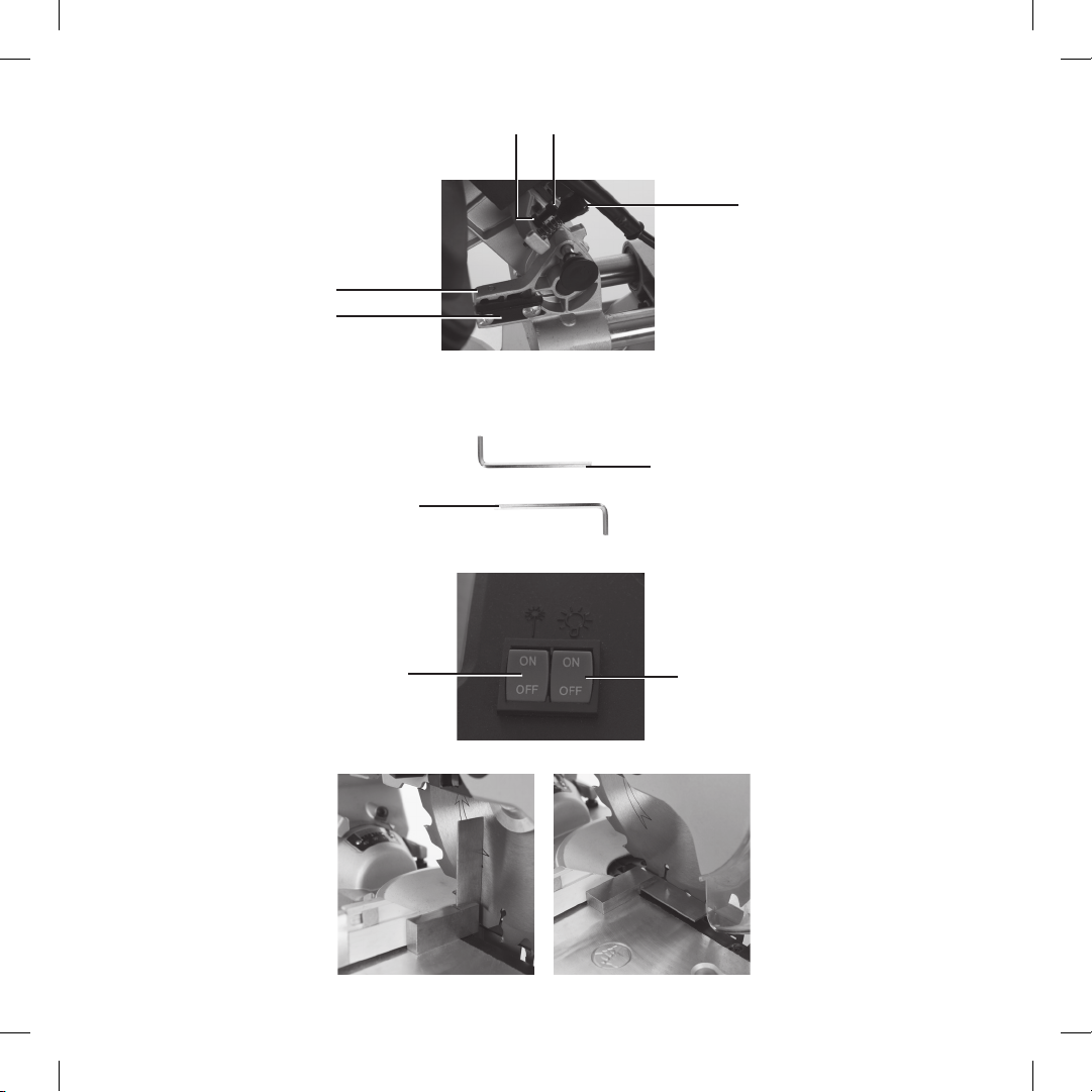
Product Familiarisation
1. Dust Port
2. Left Safety Lock-Off
3. Right Safety Lock-Off
4. Operating Handle
5. Release Lever
6. Brush Access Cover
7. Motor Vents
8. Rotation Indicator
9. Spindle Lock
10. Saw Blade
11. Rotating Blade Guard
12. Blade Channel
13. Throat Plate
14. Throat Plate Screw
15. Mitre Table Locking Knob
16. Click-Stop Lever
17. Bevel Angle Lock
18. Mitre Angle Indicator
19. Mitre Angle Indicator Screw
20. Mitre Angle Gauge
21. Mitre Table
22. Fence
23. Bench Mounting Hole
24. Workpiece Support Knob
25. Workpiece Support
26. Workpiece Support Stop
27. Clamp Base
28. Fixed Table
29. Clamp Knob
30. Clamp
31. Bevel Angle Stop Bolt
32. Bevel Angle Stop Locking Nut
33. Dust Bag
34. Sliding Bar
35. Slide Lock
36. Clamp Arm Knob
378634_Z1PKGMANPRO1.indd 8 26/10/2016 12:49

GB
9
37. Small Fence Wing Nut
38. Fence Bolt
39. Clamp Mounting Knob
40. Bevel Nut
41. Stabiliser Mounting Hole
42. Rear Carrying Handle
43. Rear Stabiliser
44. Clamp Mounting Thread
45. Clamp Mounting
46. Latching Pin
47. Carrying Handle
48. Carrying Handle Screw
49. On/Off Trigger Switch
50. Blade Label
Intended Use
Mains-powered portable or bench-mounted power tool for cutting through wood and other materials. Straight,
bevel, mitre and compound (mitre+bevel) cuts.The included saw blade is suitable for natural wood and man-
made composite wood materials.
Unpacking Your Tool
• Carefully unpack and inspect your tool. Fully familiarise yourself with all its features and functions
• Ensure that all parts of the tool are present and in good condition. If any parts are missing or damaged,
have such parts replaced before attempting to use this tool
Before Use
WARNING: Ensure the tool is disconnected from the power supply before attaching or changing any
accessories, or making any adjustments.
Bench mounting
IMPORTANT: It is recommended to mount the saw to a bench or board. Although the saw can be used
without mounting to a bench or board there is a greater safety risk in use.
• Mount the saw to a level, horizontal bench or work table using bolts, washers and locking nuts (not supplied)
through the Bench Mounting Holes (23)
• DO NOT over-tighten or the base may be damaged, or use bolts that are not a good fit for the Bench
Mounting Holes
• Alternatively, mount the saw on 13mm or thicker board, and clamp the board to the work support; this makes
it easy to relocate the saw, clamping it to a work support wherever needed
• When using a board it may be necessary to countersink the washers and nuts so the board is level on the
surface it is used on
CAUTION: Make sure the mounting surface is not warped as an uneven surface can cause binding and
inaccurate sawing
Fitting the rear stabiliser and workpiece supports
• When the saw is not fitted to a bench or board, always fit the Rear Stabiliser (43) into the two Stabiliser
Mounting Holes (41). The stabiliser helps prevent the saw from tipping in use. The Stabiliser is secured
with a screw on one side only (provided) underneath the table
• Loosen the Workpiece Support Knobs (24) and fit a Workpiece Support (25) to both sides of the saw and
retighten the screws if not pre-fitted
Dust Extraction
• The Dust Bag (33) fits over the Dust Port (1). For most efficient operation, empty the dust bag when it is no
more than half full; this allows better air flow through the bag
• Optimal dust extraction is achieved by connecting a dust extraction system or vacuum cleaner to the Dust
Port. A dust port adaptor may be required to fit your dust extraction connection
Transportation
• Fit the Carrying Handle (47) using the 2 Carrying Handle Screws (48) if not pre-fitted
• When transporting the saw, only use the Carrying Handle and Rear Carrying Handle (42) if the saw is detached
from a board or bench and no material is clamped to the base. When the saw is mounted to another surface,
move by holding the board or bench only and keep the tool upright. The saw can be stored and transported
with the cutter head lowered and secured by the Latching Pin (46); however, there is a small risk that vibration
in transit could cause the Latching Pin to move allowing the cutter head to rise
Fitting and removing the blade
WARNING: Never fit and use a blade that is visibly damaged, deformed or has dull or missing teeth.
WARNING: Wear gloves when handling blades.
WARNING: Never attempt to use a blade larger than the stated capacity of the saw, as it might come into
contact with the blade guards. Never use a blade that is too thick to allow the outer blade washer to engage
with the flats on the spindle; it will prevent the blade screw from properly securing the blade on the spindle.
WARNING: Do not use the saw to cut metal or masonry unless the saw blade is specifically designed for that
material and any dust or swarf can be correctly and safely removed in use.
WARNING: Ensure any spacers and spindle rings that may be required are provided by the manufacturer of
the blade or confirmed as compatible.
WARNING: Never fit and use a blade made from high speed steel (HSS).
IMPORTANT: Even if the blade is pre-fitted, if this is the first use of the tool always check the blade is securely
fitted before use.
Note: Cutter head is a description of the section of the tool incorporating the motor, blade assembly and
pivoting arm. On a sliding mitre saw it is the section that traverses the pole arm or arms.
1. Disconnect the mains cable from the mains socket
2. Slide the Latching Pin (46) out so the cutter head can be raised
3. Press the Release Lever (5) and lower the cutter head using the Operating Handle (4) to the lowest point with
the teeth of the Saw Blade (10) entering the Blade Channel (12)
4. Slide the Latching Pin in to hold the cutter head in this lowered position
5. Loosen the Blade Panel Screws (55 & 57) so the Blade Panel (56) can be moved slightly for clear access to the
Blade Bolt (53)
6. Press the Spindle Lock (9) and rotate the blade until the spindle locks
7. Use the Blade Hex Key (68) to remove the Blade Bolt, Blade Washer (52) (if fitted) and Blade Flange (51)
Note: The mounting has a LH thread so rotate the hex key clockwise to unscrew the bolt
8. While holding the Operating Handle move the Latching Pin so the cutter head can be raised slightly so the
existing blade can be removed
9. Check the Saw Blade that will be fitted to ensure it is not heavily worn, bent or damaged and no teeth
are missing
10. Check the Blade Direction Indicator (54) matches the Rotation Indicator (8). The teeth must point down
towards the workpiece and the maximum rpm speed stated on the Blade Label (50) must match or exceed
that of the no load speed of the saw (see Specification)
11. Check the blade mounting is clean and clear of swarf and dust and fit the blade into the recess and onto the
blade mounting
12. Press the Spindle Lock and refit the Blade Flange, Blade Washer and Blade Bolt and tighten securely anti-
clockwise without over-tightening. Do not leave the Blade Hex Key in the bolt after tightening
13. Move the Blade Panel back into position and tighten the Blade Panel Screws
14. Check the normal operation of the Rotating Blade Guard (11) by pressing the Release Lever and moving the
cutter head up and down with the Operating Handle
15. Reconnect to mains power and run the saw for a short time to make sure the blade is rotating and
operating correctly
Depth Adjustment
The mitre saw is fitted with a master depth adjustment and user depth adjustment.
To adjust the depth of cut typically for trench cuts:
1. Use a small workpiece with the required depth marked in pencil on the side
2. Setup the cutter head so you can control the height of the blade with the Operating Handle (4) as per
normal operation
3. Adjust the Depth Adjustment Knob (65) by turning clockwise so the depth of cut is reduced.The Depth
Adjustment Knob end will contact the Depth Plate (66) as the cutter head is lowered. Make adjustments
until the required depth is achieved using the small workpiece to the side of the blade
51. Blade Flange
52. Blade Washer
53. Blade Bolt
54. Blade Direction Indicator
55. Blade Panel Screw
56. Blade Panel
57. Blade Panel Screw
58. 0° Bevel Adjustment Locking Nut
59. 0° Bevel Adjustment Bolt
60. Bevel Angle Indicator Screw
61. Bevel Angle Indicator
62. Bevel Angle Gauge
63. Depth Adjustment Locking Nut
64. Depth Adjustment Bolt
65. Depth Adjustment Knob
66. Depth Plate
67. Depth Stop
68. Blade Hex Key
69. Worklight On/Off Switch
70. Laser On/Off Switch
71. Fence Hex Key
378634_Z1PKGMANPRO1.indd 9 26/10/2016 12:49

10
GB
4. Perform the cut as required
5. Reset the Depth Adjustment Knob position so it no longer prevents the cutter head from stopping before the
master depth position.
Adjusting master depth should never be done for trench cuts. Use the Depth Adjustment Knob instead. In normal
use the master depth does not need to be altered. The master depth adjustment should only be adjusted with
extreme caution as set incorrectly the blade may contact the bottom of the base. To alter the master depth
(typically fine adjustment after a blade change):
1. Loosen the Depth Adjustment Locking Nut and turn the Depth Adjustment Bolt (64) clockwise for a shallower
cut or anti-clockwise for a deeper cut.The bolt contacts the Depth Stop (67) in use as the cutter head is
lowered
2. Check the height adjustment repeatedly to ensure the blade will not contact the bottom of the Blade Channel
(12) or the sides of the Throat Plate (13) when doing a bevel cut. Check both left side and right side bevel cuts
3. Retighten the Depth Adjustment Locking Nut
Adjusting the mitre angle
The Mitre Table Locking Knob (15) is used to lock the Mitre Table (21) at the desired mitre angle. The mitre
saw cuts from 0° to 45° both left and right. To adjust the mitre angle:
1. Turn the Mitre Table Locking Knob anti-clockwise to loosen
2. Rotate the mitre angle with the Operating Handle (4) to the desired position using the Mitre Angle Indicator
(20) and Mitre Angle Gauge (19).The mitre table features positive click stops at 0, 15, 22.5, 30 and 45°
both left and right for quick setting of common mitre angles. Lift the Click-Stop Lever (16) to bypass the
click stop positionss
3. Retighten the Mitre Table Locking Knob to lock the angle setting
WARNING: Be sure to tighten the Mitre Table Locking Knob before making a cut. Failure to do so could result
in the Mitre Table moving during the cut and cause serious personal injury.
Adjusting the bevel angle
The Bevel Angle Lock (17) is used to set the blade at the desired bevel angle. The mitre saw bevel cuts from
0° to 45° to the left only. To adjust the bevel angle:
1. Ensure the Mitre Table Locking Knob (15) is tight
2. Loosen the Bevel Angle Lock by rotating anti-clockwise
3. Tilt the cutter head with the Operating Handle (4)
4. Use the Bevel Angle Indicator (61) and Bevel Angle Gauge (62) to set the required angle
5. Retighten the Bevel Angle Lock to secure in position
WARNING: Be sure to tighten the Bevel Angle Lock before making a cut. Failure to do so could result in the
saw arm moving during the cut and cause serious personal injury.
Note: Adjust the Bevel Nut (40) if necessary to ensure smooth operation of the Bevel Angle Lock or sufficient
tension to hold the Bevel Angle.
Operation
WARNING: ALWAYS wear eye protection, adequate respiratory and hearing protection, as well as suitable
non-woven gloves, when working with this tool.
Switching on and off
• To turn the saw on, depress a Safety Lock-Off (2 or 3) and hold in the On/Off Trigger Switch (49)
• To turn the saw off, release the On/Off Trigger Switch
Laser and LED worklight
• To switch the laser on and off use the Laser On/Off Switch (70).This indicates the cut line on the workpiece
• To switch the LED worklight on and off use the Worklight On/Off Switch (69). It provides additional illumination
of the cutting area
Note: Both laser and LED worklight can be used together and are powered independently of the mitre saw On/
Off Trigger Switch (49).
Making a cut
• A compound mitre cut involves using a mitre angle and a bevel angle at the same time. It is used to make
picture frames, cut mouldings, make boxes with sloping sides, and for roof framing
• Always make a test cut on a piece of scrap wood before cutting the workpiece
1. Pull on the Release Lever (5) and lift the cutter head to its full height
2. Loosen the Mitre Table Locking Knob (15)
3. Rotate the Mitre Table (21) until the Mitre Angle Indicator (18) aligns with the desired angle on the
Mitre Angle Gauge (20)
4. Retighten the Mitre Table Locking Knob
WARNING: Be sure to tighten the Mitre Table Locking Knob before making a cut. Failure to do so could result in
the table moving during the cut, causing serious personal injury.
5. Loosen the Bevel Angle Lock (17) and move the cutter head to the left to the desired bevel angle (between 0°
and 45° as indicated by the Bevel Angle Indicator (61)). Tighten the Bevel Angle Lock
6. Place the workpiece flat on the table with one edge securely against the Fence (22). If the board is warped,
place the convex side against the fence. If the concave side is placed against the fence, the board could break
and jam the blade
7. When cutting long pieces of timber, support the opposite end of the timber with Workpiece Supports (25), a
roller stand or a work surface that is level with the saw table
8. Use the clamp to secure the workpiece wherever possible using the Clamp Base (27) against the workpiece
and adjusting the height with the Clamp Knob (29)
Note: The clamp can be positioned on the other side of the saw using the Clamp Mounting (45) and moving the
Clamp Mounting Knob (39) to the other Clamp Mounting Knob Thread (44).
9. Before turning on the saw, perform a dry run of the cutting operation to check that there are no problems
10. Hold the Operating Handle (4) firmly and depress a Safety Lock-Off (2 or 3) and squeeze the On/Off Trigger
Switch (49). Allow the blade to reach maximum speed
11. Press the Release Lever (5) and slowly lower the blade into and through the workpiece
12. Release the On/Off Trigger Switch and allow the Saw Blade to stop rotating before raising the blade out of
the workpiece. Wait until the blade stops before removing the workpiece
Accessories
• A range of accessories and consumables, including saw blades, additional clamps and personal protective
equipment, is available from your GMC stockist. Spare parts can be obtained from toolsparesonline.com
Maintenance
WARNING: ALWAYS disconnect from the power supply before carrying out any inspection, maintenance
or cleaning.
Bevel Angle Adjustment
Checking angle
1. Turn the Bevel Angle Lock (17) anti-clockwise and position the cutter head at the maximum height with the
Bevel Angle Indicator (61) at 0° on the Bevel Angle Gauge (62). Tighten the Bevel Angle Lock
2. Lower the cutter head so the exposed blade is in the Blade Channel (12) of the Throat Plate (13) and lock in
this position with the Latching Pin (46)
3. Recheck that the cutter head is upright and the Bevel Angle Indicator is still at 0°
4. Place a set square on the table with one short edge against the Mitre Table (21) and the other short edge
against the blade (avoiding the saw teeth) - see Image A
Note: If the blade is not square (90°) with the Mitre Table, adjustment is required
Changing 0° angle
1. Use 0° Bevel Adjustment Bolt (59) and 0° Bevel Adjustment Locking Nut (58) to set the cutter head resting
position at exactly 0°
2. Turn the Bevel Angle Lock (17) anti-clockwise and set the bevel angle to 45° then tighten the Bevel Angle Lock
3. Turn the Bevel Adjustment Locking Nut on the 0° Bevel Adjustment Bolt so it is at a higher position, and make
a small adjustment to the Bolt (the adjustment should be very small)
4. Turn the Bevel Angle Lock (17) anti-clockwise and set the bevel angle to the 0° resting position then tighten
the Bevel Angle Lock
5. Recheck the 90° alignment against the set square and blade
6. Repeat the above steps 2-4 until a 90° angle is achieved
7. Tighten the Bevel Angle Lock
8. A minor adjustment can be made to the Bevel Angle Indicator (61) by loosening the Bevel Angle Indicator
Screw (60) and adjusting the position of the Bevel Angle Indicator so it is set to 0° when the set square is at a
90° angle (Image A)
378634_Z1PKGMANPRO1.indd 10 26/10/2016 12:49

GB
11
Note: To adjust the 45° bevel stop position use the Bevel Angle Stop Locking Nut (32) and Bevel Angle Stop Bolt
(31) using the 45° side of a set square adapting the same procedure as above.
Mitre Angle 90° Adjustment
The major adjustment of the mitre angle 0° position is achieved by altering the Fence (22) position
1. Loosen the Mitre Table Locking Knob (15) by turning anti-clockwise and lift the Click-Stop Lever (16)
2. Rotate the Mitre Table (21) with the Operating Handle (4) to the 0° position using the Mitre Angle Indicator
(18) and Mitre Angle Gauge (20)
3. Retighten the Mitre Table Locking Knob to lock the angle setting
4. Lower the cutter head so the exposed blade is in the Blade Channel (12) of the Throat Plate (13) and lock in
this position with the Latching Pin (46)
5. Use a set square to check the 90° angle between the Fence (22) and the Saw Blade (10) - see Image B
6. Adjust the position of the Fence by loosening the 4 Fence Bolts (38) with the Fence Hex Key (71) so the
Fence is at exactly 90° using the set square
7. Retighten the 4 Fence Bolts
8. Release the Latching Pin and allow the cutter head to return to its top position
Replacing the Throat Plate
IMPORTANT: If the Throat Plate (13) is damaged or heavily worn, it must be replaced to ensure safe operation of
the tool. To replace the Throat Plate:
1. If necessary to remove the Throat Plate unscrew and remove the 4 Fence Bolts (38) with the Fence Hex Key
(71) and remove the Fence (22).
2. Unscrew the Throat Plate Screws (14) securing the Throat Plate and remove the Throat Plate
3. Clean the Blade Channel (12) and fit the new Throat Plate. Refit and tighten the Throat Plate screws
4. If previously removed refit the Fence back to the correct position and refit the Fence Bolts (38). Ensure the
Fence is at the correct angle with a set square before tightening the Fence Bolts following ‘Mitre Angle 90°
Adjustment’
General inspection
• Regularly check that all the fixing screws are tight
• Inspect the supply cord of the tool, prior to each use, for damage or wear. Repairs should be carried out by
an authorised GMC service centre. This advice also applies to extension cords used with this tool
Cleaning
• Keep your tool clean at all times. Dirt and dust will cause internal parts to wear quickly, and shorten the
machine’s service life. Clean the body of your machine with a soft brush, or dry cloth. If available, use clean,
dry, compressed air to blow through the ventilation holes
• Clean the tool casing with a soft damp cloth using a mild detergent. Do not use alcohol, petrol or strong
cleaning agents
• Never use caustic agents to clean plastic parts
Lubrication
• Slightly lubricate all moving parts at regular intervals with a suitable spray lubricant
Brushes
• Over time the carbon brushes inside the motor may become worn
• Excessively worn brushes may cause loss of power, intermittent failure, or visible sparking
• To replace the brushes, remove the Brush Access Covers (6) from both sides of the machine. Remove the
worn brushes and replaced with new. Replace Brush Access Covers.Alternatively, have the machine serviced
at an authorised service centre
Note: Always replace carbon brushes in pairs.
Storage
• The cutter head can be lowered and secured by the Latching Pin (36) to make the saw a smaller size for
storage. Store this tool carefully in a secure, dry place out of the reach of children
Disposal
Always adhere to national regulations when disposing of power tools that are no longer functional and are
not viable for repair.
• Do not dispose of power tools, or other waste electrical and electronic equipment (WEEE), with
household waste
• Contact your local waste disposal authority for information on the correct way to dispose of power tools
378634_Z1PKGMANPRO1.indd 11 26/10/2016 12:49

12
GB
Troubleshooting
Problem Possible Cause Solution
No
operation
Plug fuse Replace fuse
Worn brushes Have brushes replaced by an authorised GMC service centre
Power tool fault Contact an authorised GMC service centre
Cutting performance poor
Teeth worn or damaged Replace Saw Blade (10)
Incorrect Saw Blade type Replace Saw Blade with correct type for material being sawed
Incorrect Saw Blade specification Ensure Saw Blade meets the required blade specification for this mitre saw
Incorrectly fitted Saw Blade Remove Saw Blade and refit exactly as per the instructions in this manual
Power tool vibrating excessively in use
Saw blade distorted, bent or damaged Replace Saw Blade immediately
Saw blade incorrectly mounted Re-fit Saw Blade exactly as per the instructions in this manual
Machine fault Contact an authorised GMC service centre
Mitre or bevel angle difficult to adjust Build-up of sawdust Vacuum up sawdust
378634_Z1PKGMANPRO1.indd 12 26/10/2016 12:49

GB
13
The technical documentation is kept by: GMC Tools
Date: 13/09/2016
Signed:
Mr Darrell Morris
Managing Director
Name and address of the manufacturer:
Powerbox International Limited, Company No. 06897059. Registered address: Powerbox, Boundary Way,
Lufton Trading Estate, Yeovil, Somerset, BA22 8HZ, United Kingdom.
CE Declaration of Conformity
The undersigned: Mr Darrell Morris
as authorised by: GMC Tools
Declares that:
This declaration has been issued under the sole responsibility of the manufacturer. The object of the
declaration is in conformity with the relevant Union harmonisation Legislation.
Identification code: GM210S
Description: 1800W Double Bar Sliding Mitre Saw 210mm
Conforms to the following directives and standards:
• Machinery Directive 2006/42/EC
• EMC Directive 2014/30/EU
• RoHS Directive 2011/65/EU
• EN 61029-1:2009+A11:2010
• EN 61029-2-9:2012+A11:2013
• EN 62321:2009
• EN 55014-1:2006+A1:2009+A2:2011
• EN 61000-3-2:2014
• EN 61000-3-11:2000
Notified body: TÜV SÜD Product Service
Guarantee
To register your guarantee visit our web site at www.gmctools.com and enter your details*.
Your details will be included on our mailing list (unless indicated otherwise) for information on future
releases. Details provided will not be made available to any third party.
Purchase Record
Date of Purchase:
Model: GM210S
Serial Number:
(located on motor housing)
Retain your receipt as proof of purchase.
If registered within 30 days of purchase GMC guarantees to the purchaser of this product that if any part
proves to be defective due to faulty materials or workmanship within 24 MONTHS from the date of original
purchase, GMC will repair or, at its discretion, replace the faulty part free of charge. This guarantee does
not apply to commercial use nor does it extend to normal wear and tear or damage as a result of accident,
abuse or misuse.
* Register online within 30 days of purchase.
Terms & conditions apply.
This does not affect your statutory rights.
378634_Z1PKGMANPRO1.indd 13 26/10/2016 12:49

14
NL
Introductie
Hartelijk dank voor de aanschaf van dit GMC- gereedschap. Deze instructies bevatten informatie die u nodig
hebt voor een veilige en doeltreffende bediening van dit product. Dit product heeft unieke kenmerken. Zelfs als
u bekend bent met gelijksoortige producten dient u deze handleiding zorgvuldig door te lezen, zodat u in staat
bent alle voordelen te benutten. Houd deze handleiding bij de hand en zorg ervoor dat alle gebruikers van dit
gereedschap de handleiding hebben gelezen en volledig hebben begrepen.
Beschrijving symbolen
Op het gegevensplaatje van uw gereedschap kunnen zich symbolen bevinden. Deze vertegenwoordigen
belangrijke productinformatie en gebruiksinstructies.
Draag gehoorbescherming
Draag een veiligheidsbril
Draag een stofmasker
Draag een veiligheidshelm
Draag handschoenen
Lees de handleiding
Giftige dampen of gassen!
Gebruik niet de regen of in vochtige omstandigheden!
Belangrijke veiligheidshulpmiddelen! Zorg voor een goede werking, onderhoud volgens
instructies en MAAK NIET onbruikbaar!
Stofafvoer vereist of aanbevolen
Laser waarschuwing!
Voorzichtig!
Beschermingsklasse II (dubbel geïsoleerd voor bijkomende bescherming)
WAARSCHUWING: Bewegende delen kunnen ernstig letsel veroorzaken.
Let op: terugslaggevaar!
Milieubescherming Elektrische producten mogen niet met het normale huisvuil worden
weggegooid. Indien de mogelijkheid bestaat, dient u het product te recyclen.Vraag de
plaatselijke autoriteiten of winkelier om advies betreffende recyclen.
Voldoet aan de relevante wetgeving en veiligheidsnormen
Specificaties
Vertaling van de originele instructies
Technische afkortingen en symbolen
Modelnummer: GM210S
Spanning: 230-240 V~ 50 Hz
Vermogen: 1800 W
Onbelaste snelheid: 4800 min-1
Max. zaagdiepte: 60 mm
Max. bladformaat: Ø210 mm
Asgat: 25,4 mm (1")
Inbegrepen zaagblad: Ø210 mm x Ø25,4 mm x 2,6 mm x 24T
Tafel verstekhoeken: 0° tot 45° links & rechts (0, 15, 22.5, 30 & 45° klikstops)
Afschuiningsbereik: 0° to 45° links
Rechte snede: 0° verstek x 0° schuine 260 x 60 mm
Versteksnede: 45° (L&R) x 0° 170 x 60 mm
Afschuiningssnede: 0° verstek x schuine (L) 45° 260 x 30 mm
Schuin afkorten: 45° schuine (L) x verstek 45° (R of L) 170 x 30 mm
Beschermingsniveau: IP20
Laser klasse: II
Laser golflengte: 400 - 700 nm
Laser uitgangsvermogen: ≤1 m W
Stroomsnoer lengte: 2 m
Beschermingsklasse:
Gewicht: 14 kg
Met het oog op onze aanhoudende productontwikkeling kunnen de specificaties van GMC producten zonder
voorafgaande kennisgeving worden gewijzigd.
VVolts
~, AC Wisselstroom
A, mA Ampere, milli-Amp
n0Onbelaste snelheid
nNominale snelheid
λGolflengte
°Graden
ØDiameter
Hz Hertz
, DC Gelijkstroom
W, kW Watt, kilowatt
/min or min-1 Bewerkingen per minuut
rpm Toeren per minuut
nm Nanometer
dB(A) Geluidsniveau decibel (A-gewogen)
m/s2Meter per seconde² (trillingsmagnitude)
378634_Z1PKGMANPRO1.indd 14 26/10/2016 12:49

NL
15
WAARSCHUWING: Bij een geluidsintensiteit van 85 dB(A) of hoger is het dragen van gehoorbescherming en
het beperken van de blootstellingstijd vereist. Bij oncomfortabel hoge geluidsniveaus, zelfs met het dragen
van gehoorbescherming, stopt u het gebruik van de machine onmiddellijk. Controleer de pasvorm en het
geluiddempingsniveau van de bescherming, infunctie van het geluidsniveau dat door uw gereedschap
geproduceerd wordt
WAARSCHUWING: Blootstelling aan trilling resulteert mogelijk in gevoelloosheid, tinteling en een vermindert
greepvermogen. Langdurige blootstelling kan leiden tot chronische condities. Beperk de blootstellingsduur en
draag anti-vibratie handschoenen. Vibratie heeft een grotere invloed op handen met een temperatuur lager
dan een normale, comfortabele temperatuur. Maak gebruik van de informatie in de specificaties voor het
bereken van de gebruiksduur en frequentie van de machine.
Geluid- en trillingsniveaus in de specificatie zijn vastgesteld volgens EN60745 of een gelijksoortige
internationale norm. De waarden gelden voor een normaal gebruik in normale werkomstandigheden. Een
slecht onderhouden, onjuist samengestelde of onjuist gebruikte machine produceert mogelijk hogere geluids-
en trillingsniveaus. www.osha.europa.eu biedt informatie met betrekking tot geluids- en trillingsniveaus op
de werkplek wat mogelijk nuttig is voor regelmatige gebruikers van machines.
Algemene veiligheid
WAARSCHUWING: Bij het gebruik van elektrische machines horen basis veiligheidsvoorzorgmaatregelingen
opgevolgd te worden om de kans op brand, elektrische schokken en persoonlijk letsel te minimaliseren. Lees
de instructies voor gebruik volledig door en bewaar deze bij de machine voor toekomstig gebruik.
WAARSCHUWING: De machine is niet geschikt voor gebruik door personen met een verminderde mentale of
fysieke bekwaamheid of een gebrek aan ervaring, tenzij de persoon wordt begeleid of geïnstrueerd door een
persoon verantwoordelijk voor de veiligheid
LET OP: Het gebruik van de machine voor doeleinden, anders dan waarvoor de machine is bestemd resulteert
mogelijk in gevaarlijke situaties en serieus persoonlijk letsel
De term “elektrisch gereedschap” in alle hieronder vermelde waarschuwingen heeft betrekking op uw
elektrische gereedschap dat op de stroom is aangesloten (met een snoer) of met een accu wordt gevoed
(snoerloos).
1 – Veiligheid in de werkruimte - Rommelige en donkere ruimtes leiden vaak tot ongelukken.
2 – Denk aan de werkplaatsomgeving
- Stel gereedschap niet bloot aan regen
- Gebruik gereedschap niet in vochtige of natte omstandigheden
- Houdt uw werkplaats goed verlicht
- Gebruik gereedschap niet in de nabijheid van ontvlambare vloeistoffen of gassen
3 – Bescherm uzelf tegen elektrische schok – Voorkom het contact met geaarde oppervlakken (als leidingen,
radiatoren, koelkasten).
4 – Houd kinderen en omstanders uit de buurt – Laat mensen, vooral kinderen, de machine en
verlengsnoeren niet aanraken en houd ze op afstand
5 – Berg gereedschap wat niet in gebruik is op – Berg gereedschap dat niet in gebruikt is op een droge plek,
buiten het bereik van kinderen op
6 – Forceer gereedschap niet – Uw machine functioneert optimaal op de bestemde gebruikssnelheid
7 – Gebruik de juiste machine – Forceer kleine machine niet voor het uitvoeren van grote werkzaamheden.
Gebruik gereedschap niet voor doeleinden waarvoor ze niet bestemd zijn.
8 – Draag de juiste uitrusting
- Loshangende kleding en sieraden kunnen door bewegende onderdelen gegrepen worden
- Het dragen van niet-slippende schoenen is aangeraden voor buitenwerk
- Bedek lang haar
9 – Draag de benodigde beschermingsmiddelen
- Draag een veiligheidsbril
- Draag een stofmasker bij stof producerende werkzaamheden
WAARSCHUWING: Wanneer de beschermende uitrusting niet gedragen wordt is de kans opeen ongeval groter
en is de ernst van voorvallende ongevallen groter
10 – Sluit gereedschap op een stof-ontginningssysteem aan – Wanneer de machine is voorzien van een
stofpoort, sluit u deze op een ontginningssysteem aan
11 – Misbruik het stroomsnoer niet – Trek nooit aan het stroomsnoer om de stekker uit het stopcontact
te halen. Houdt het stroomsnoer uit de buurt van warmte, olie en scherpe randen. Beschadigde snoeren
vergroten de kans op elektrische schok
12 – Klem uw werk vast – Klem uw werkstuk wanneer mogelijk stevig vast
13 – Reik niet te ver - Blijf altijd stevig en in balans staan
14 – Onderhoud uw gereedschap zorgvuldig
- Het scherp en schoon houden van snijgereedschap zorgt voor een gemakkelijkere machine controle en
een kleinere kans op het buigen en breken
- Volg smeerinstructies op
- Controleer stroomsnoeren regelmatig op beschadiging en laat deze bij een geautoriseerd service
center repareren
- Laat stroomsnoeren bij een geautoriseerd service center vervangen
- Houdt handvaten schoon, droog en vrij van olie en vet
WAARSCHUWING: Velen ongelukken worden veroorzaakt door slecht onderhouden machines
15 – Ontkoppel machines van de stroombron – wanneer niet in gebruik, voor onderhoud en bij het vervangen
van accessoires ontkoppelt u de machine van de stroombron
16 – Verwijder sleutels – Maak van het controleren op gereedschapssleutels een gewoonte
17 – Voorkom onnodig starten – Zorg ervoor dat de aan-/uitschakelaar bij het aansluiten op de stroombron, het
plaatsen van een accu of het vervoeren in de uit-positie staat
WAARSCHUWING – Het onnodig starten van de machine kan leiden tot serieuze verwondingen
18 – Het gebruik van buiten verlengsnoeren – Wanneer gereedschap buiten gebruikt wordt, maakt u gebruik
van verlengsnoeren, geschikt voor buiten. Dit vermindert de kans op elektrische schok
19 – Blijf alert
- Houd uw aandacht op het werk, gebruik uw gezonde verstand en gebruik machines niet wanneer vermoeid
- Gebruik het elektrisch gereedschap niet wanneer u vermoeid bent of onder invloed van drugs, alcohol of
medicijnen
WAARSCHUWING: Onoplettendheid tijdens het bedienen van elektrisch gereedschap kan leiden tot ernstig letsel
20 – Controleer beschadigde onderdelen
- Controleer voor verder gebruik of de machine als bestemd functioneert
- Controleer bewegende delen op uitlijning, beschadiging, montage en andere gesteldheden die gebruik van
de machine mogelijk beïnvloeden
- Een beschadigde beschermkap hoort bij een geautoriseerd service center gerepareerd of vervangen te
worden, tenzij anders vermeld in deze handleiding
- Laat defecte schakelaars bij een geautoriseerd service center repareren
WAARSCHUWING: Gebruik de machine niet met een defecte aan-/uitschakelaar. De schakelaar hoort voor
gebruik gerepareerd te worden
21 – Laat uw machine te allen tijde door een gekwalificeerd persoon repareren – Laat uw machine te allen
tijde door een gekwalificeerd persoon repareren om gevaarlijk gebruik te vermijden
WAARSCHUWING: Maak bij onderhoud enkel gebruik van identieke vervangende onderdelen
WAARSCHUWING: Laat een beschadigd stroomsnoer door de verkoper of een geautoriseerd service
center vervangen
22 – Stekker horen overeen te komen met het te gebruiken stopcontact – Stekkers mogen niet aangepast
worden. Gebruik geen adapters op geaarde machines. Overeenkomende stekkers en stopcontacten
verminderen de kans op elektrische schok
23 – Indien het onvermijdelijk is elektrisch gereedschap te gebruiken in een vochtige omgeving, gebruik
dan een energiebron met een aardlek beveiliging (Residual Currency Device). Het gebruik van een RCD
vermindert het risico op een elektrische schok
WAARSCHUWING: Voordat u de machine op de stroombron aansluit controleert u of het voltage van de
stroombron overeenkomt met het voltage op het gegevensplaatje op de machine. Een stroombron met een
hogere spanning kan zorgen voor ernstige verwondingen aan de gebruiken en schade aan de machine. Een
stroombron met een lagere spanning kan de motor beschadigen. Plug de stekker bij twijfel niet in de stroombron.
Verstekzaag veiligheid
WAARSCHUWNG: Voordat u de machine op de stroombron aansluit, controleert u of de spanning gelijk is aan
de spanning weergegeven op het gegevensplaatje van de verstekzaag. De aansluiting op een stroombron met
een hogere spanning kan resulteren in serieuze verwondingen aan de gebruiker en beschadigingen aan de
machine. Een lagere spanning is schadelijk voor de motor. Sluit de machine bij enige twijfel niet aan.
Geluid en trilling:
Geluidsdruk LPA:93,5 dB(A)
Geluidsvermogen LWA: 106,5 dB(A)
Onzekerheid K: 3 dB
Trilling ah(hoofdhandvat) 6 m/s2
Onzekerheid K: 1,5 m/s2
De geluidsintensiteit voor de bediener kan 85 dB(A) overschrijden en de gehoorbescherming is noodzakelijk.
378634_Z1PKGMANPRO1.indd 15 26/10/2016 12:49

16
NL
WAARSCHUWING
• Houdt de machine enkel bij de geïsoleerde oppervlakken vast. Wanneer het frees bit in contact komt met
het stroomsnoer of enige andere stroomdraden komen de metalen onderdelen mogelijk onder stroom te staan
wat kan resulteren in elektrische schok
• Gebruik enkel zaagbladen met een juist formaat en vorm asgat. Bladen met een ongeschikt asgat roteren
onjuist wat resulteert in controleverlies
• Gebruik geen beschadigde of ongeschikte blad sluitringen en bouten. De sluitringen en bladbout zijn
speciaal ontworpen voor uw verstekzaag, voor optimale prestatie en veiligheid
• Pas de zaagdiepte aan de dikte van het werkstuk aan
• Houd uw handen uit de buurt van het zaagblad
BELANGRIJK: Als u enigszins onzeker bent betreft de juiste gebruikswijze, gebruik de machine dan niet
a) Laat niemand, jonger dan 18 jaar oud, de zaag gebruiken
b) Wanneer u de zaagt gebruikt, hoort u te allen tijde bescherming te dragen. Denk hierbij aan een veiligheidsbril,
gehoorbeschermers, mondkapje, beschermende kleding en handschoenen
c) Elektrisch handgereedschap kan trillingen veroorzaken. Trillingen kunnen ziektes veroorzaken. Handschoenen
die de handen van de bediener warmhouden kunnen een goede circulatie van het bloed in de vingers
bevorderen. Gebruik handgereedschap niet langdurig zonder onderbreking
d) Gebruik wanneer mogelijk een stof ontginningssysteem om het zaagsel/afval op te vangen
e) Zaag geen materiaal, dikker dan beschreven in de specificaties van deze handleiding
f) Verstekzagen zijn niet ontworpen voor het zagen van brandhout. Zorg ervoor dat het hout droog is met vlakke
oppervlakken zodat het stevig op de verstektafel en tegen de geleider ligt
g) Geleid het blad enkel door het werkstuk wanneer de machine ingeschakeld is. Anders bestaat er een grote
kans op terugslag
h) Pas de zaagdiepte aan de dikte van het werkstuk aan
i) Verwijder zaagsel dichtbij het blad niet met de blote hand. Zorg ervoor dat de machine ontkoppeld is van de
stroombron en gebruik een geschikte borstel
j) Gebruik enkel zaagbladen die aanbevolen zijn door de fabrikant en overeenkomen met richtlijn EN 847-1
k) Draag geschikte kleding. Draag geen loshangende kleding of sieraden. Houd haren, kleding en handschoenen
uit de buurt van bewegende delen. Loshangende kleding, sieraden, los hangende haren en handschoen rafels
kunnen vast komen te zitten in het zaagblad
l) Zorg ervoor dat de machine uit de buurt van hoog opgeborgen voorwerpen gebruikt wordt. Dankzij de
trillingen van de machine vallen de voorwerpen mogelijk naar beneden
m) Berg reserve zaagbladen die niet op de machine gemonteerd zijn in een geschikte container op om uzelf te
beschermen tegen sneden
n) Zorg ervoor dat het zaagblad geschikt is voor het te zagen materiaal en dat de maximale snelheid van het
blad niet overschreden wordt door de onbelaste snelheid van de machine
o) Wanneer de as van de verstekzaag groter is dan het asgat van het blad, dient u gebruik te maken van
geschikte asringen
p) Bij het verplaatsen van de machine houdt u deze enkel bij het transporthandvat vast en zorgt u ervoor dat de
machine in de lage positie vergrendeld is
q) Verwijder afvalmateriaal en zaagsel niet voordat u de zaagkop verhoogd en het zaagblad bedekt is door de
beschermkap
r) Zorg voor een goede werkstukondersteuning. Grote panelen gaan mogelijk hangen en het zaagblad zo buigen.
Ondersteun het werkstuk aan beide zijden van het zaagblad en aan de randen van het werkstuk
s) Houdt alle ondersteuningsmaterialen en stroomsnoeren uit de buurt van het zaagblad
t) Zorg dat het werkstuk stevig gemonteerd is, en niet te ver uitsteekt over de werkbank om buiging van het
zaagblad en controleverlies te voorkomen
u) Ga niet in lijn met het zaagblad staan. Ga bij het gebruik van de machine aan de zijkant staan om de kans op
letsel bij terug te minimaliseren
v) Let op de draairichting van de motor en het zaagblad
w) Inspecteer het werkstuk en verwijder alle voorwerpen in de buurt van de zaag voordat u begint met zagen
x) Oefen tijdens het zagen geen zijwaartse of draaiende druk op het zaagblad uit
y) Wanneer het zaagblad niet tot de volledige breedte van het werkstuk reikt, of wanneer het zaagblad in het
werkstuk klemt, laat u de zaag volledig tot stilstand komen voordat u de zaag uit het werkstuk tilt
z) Wanneer het zaagblad vast geklemd zit in het werkstuk hoort u de machine uit te schakelen voordat u het
blad los probeert te krijgen
1. Kijk uit voor rondvliegend zaagafval. Het is de gebruikers verantwoordelijkheid omstanders te beschermen
tegen rondvliegend zaagafval
2. Wanneer u onderbroken wordt tijdens het zagen, maak de snede dan eerst af en schakel de machine uit
voordat u opkijkt
3. Controleer voor elk gebruik of de onderste beschermkap juist functioneert. Gebruik de machine niet wanneer
de beschermkap vrij beweegt en volledig sluit. Vergrendel de beschermkap nooit in de open positie. Wanneer
de zaag per ongeluk valt raakt de beschermkap mogelijk beschadigd. Zorg ervoor dat de beschermkap in elke
hoek en op elke zaagdiepte vrij beweegt en het zaagblad of enig ander deel van de machine niet raakt
4. Gebruik de machine niet zonder beschermkappen
5. Controleer regelmatig of alle bouten, moeren en andere bevestigingen goed vastgedraaid zijn
6. Gebruik geen HSS zaagbladen
7. Laat het tafelblad, wanneer beschadigt of versleten, door de fabrikant vervangen
De zaagmachine mag alleen gebruikt worden voor het voorgeschreven doel. Elk ander doel dan vermeld
staat in deze handleiding wordt beschouwd als misbruik. De gebruiker en niet de fabrikant is vervolgens
aansprakelijk voor eventuele schade of eventueel letsel ten gevolge van dergelijke gevallen van misbruik. De
fabrikant is niet verantwoordelijk voor eventuele wijzigingen die gedaan worden aan het gereedschap, noch voor
eventuele schade die het resultaat is van dergelijke wijzigingen. Zelfs wanneer de machine als voorgeschreven
gebruikt wordt zijn alle riscifactoren nooit volledig uit te sluiten
Laser veiligheid
De laser gebruikt in de machine is een klasse 2 laser met een maximaal vermogen van ≤1mW en een golflengte
van 400-700 nm.
Hoewel het lasersystem normaal gesproken geen optisch gevaar is, het staren in de laser leid echter mogelijk
tot blindheid.
WAARSCHUWING: Vermijd rechtstreeks oogcontact.
Volg alle onderstaande veiligheidsregels op:
• Gebruik en onderhoud de laser in overeenstemming met de instructies van de fabrikant
• Schakel de laser niet in voordat de machine klaar is voor gebruik
• Richt de laser niet op uzelf, personen om u heen en reflecterende materialen anders dan het werkstuk
• Richt de laser enkel op een stevig werkstuk zonder reflecterende oppervlakken. Reflecterend materiaal als
staal kaatst de laser mogelijk terug in de richting van de gebruiker
• Aanpassingen aan, en het vervangen van de laser hoort gedaan te worden door de fabrikant of een
geautoriseerd persoon. De laser hoort met hetzelfde type laser vervangen te worden
LET OP: Het gebruik van de laser, anders dan beschreven, kan resulteren in schadelijke radiatie blootstelling
Verwijs naar de relevante EN richtlijnen, EN60825-1/1A:2002 voor meer informatie betreft lasersystemen
Onderdelenlijst
1. Stofopening
2. Linker veiligheidsschakelaar
3. Rechter veiligheidsschakelaar
4. Gebruikshandvat
5. Verloshendel
6. Koolstofborsteldoppen
7. Motor ventilatiegaten
8. Rotatierichting indicator
9. As-vergrendeling
10. Zaagblad
11. Roterende bladbeschermkap
12. Bladkanaal
13. Keelplaat
14. Keelplaatschroef
15. Verstektafel vergrendelknop
16. Klikstop hendel
17. Afschuiningshoekvergrendeling
18. Verstekhoekindicator
19. Verstekhoek indicatorschroef
20. Verstekhoekmeter
21. Verstektafel
22. Geleider
23. Werkbank montagegaten
24. Werkstuk steunknop
25. Werkstuksteun
26. Werkstuksteunstop
27. Klemvoet
28. Vaste tafel
29. Klemknop
30. Klem
31. Afschuiningshoek stopbout
32. Afschuiningshoek vergrendelmoer
33. Stofzak
34. Schuifstaaf
35. Schuifvergrendeling
36. Klem arm knop
37. Kleine geleider vleugelmoer
38. Geleiderbout
39. Klemmontageknop
40. Afschuiningsmoer
41. Stabilisator montagegat
42. Achter draaghandvat
43. Achter stabilisator
44. Klemsamenstelling draad
45. Klemsamenstelling
46. Vergrendelpin
47. Draaghandvat
48. Draaghandvatschroef
49. Aan/uit trekker schakelaar
50. Blad specificaties
51. Blad flens
52. Blad sluitring
53. Blad bout
54. Blad rotatierichting indicator
55. Blad paneelschroef
56. Blad paneel
57. Blad paneelschroef
58. 0° afschuiningshoek
vergrendelmoer
59. 0° afschuiningshoek stelbout
60. Afschuiningshoek
indicatorschroef
61. Afschuiningshoekindicator
62. Afschuiningshoekmeter
63. Diepte stel vergrendelmoer
64. Dieptestelbout
65. Dieptestelknop
66. Diepteplaat
67. Dieptesop
68. Blad zeskantsleutel
69. Werklicht aan-/uitschakelaar
70. Laser aan-/uitschakelaar
71. Geleider zeskantsleutel
378634_Z1PKGMANPRO1.indd 16 26/10/2016 12:49

NL
17
Gebruiksdoel
Draagbare of werkbank gemonteerde verstekzaagmachine voor het zagen in hout en andere materialen.
Rechte, verstek, schuine en schuine versteksneden. Het inbegrepen TCT zaagblad is geschikt voor natuurlijk
hout, en composiet hout.
Het uitpakken van uw gereedschap
• Pak uw toestel / gereedschap uit. Inspecteer het en zorg dat u met alle kenmerken en functies
vertrouwd raakt
• Controleer of alle onderdelen aanwezig zijn en in goede staat verkeren. Als er onderdelen ontbreken of
beschadigd zijn, zorg dan dat deze vervangen worden voor u dit toestel / gereedschap gebruikt
Voor gebruik
WAARSCHUWING: Ontkoppel de machine van de stroombron voordat u accessoires wisselt of enige
aanpassingen maakt
Werkbank montage
BELANGRIJK: Het is aanbevolen de machine op een werkbank te bevestigen. De machine kan vrij gebruikt
worden maar de montage op een werkbank verminderd het risico op gevaren
• Monteer de machine, met gebruik van de bouten, sluitringen en vergrendelmoeren (niet inbegrepen) door de
bevestigingsgaten (23) op de werkbank
• Gebruik geen bouten die niet goed passen in de bevestigingsgaten en draai de bouten niet te strak vast waar
u de voet mogelijk beschadigd
• De machine kan tevens op een 13 mm of dikkere plank gemonteerd worden. De plank is zo verplaatsbaar en
kan waar nodig op een geschikte werkondersteuning geklemd worden
• Bij de montage op een plank is het mogelijk vereist de schroeven te verzinken zodat de plank evenwijdig op
het oppervlak ligt
Let op: Zorg ervoor dat het werkoppervlak recht is. Een gebogen oppervlak zorgt mogelijk voor
onnauwkeurige zaagresultaten
Het bevestigen van de achter stabilisator
• Wanneer de machine niet op een werkbank op plank gemonteerd is maakt u gebruik van de stabilisator (43).
De stabilisator helpt het voorkomen van omkantelen van de machine. Gebruik de bevestigingsmiddelen om de
stabilisator op de bevestigingsgaten (31) te bevestigen
• Draai de werkstuk steunknoppen (24) los, bevestig een werksteun (25) aan beide zijden van de machine en
draai de schroeven weer vast, indien niet vooraf gemonteerd.
Stofontginning
• De stofzak (33) past op de stofpoort (1). Voor de meest efficiënte werking leegt u de stofzak voordat deze
halfvol is. Dit zorgt voor een betere luchtstroom door de zak
• Voor een optimale stofontginning sluit u een stofzuiger of ander ontginningssysteem op de stofpoort aan. Een
adapter is mogelijk vereist
Verplaatsing/transport
• Als het draaghandvat (47) niet op de machine gemonteerd is, monteert u het met gebruik van de
handvatschroeven (48)
• Wanneer de machine niet gemonteerd is op een werkbank of plank, draagt u de machine aan het achter
draaghandvat (42) voor verplaatsing. Wanneer de machine op een plank gemonteerd is, draagt u de plank en
zorgt u ervoor dat de machine rechtop blijft. De machine is op te bergen en te transporteren met de zaagkop
verlaagt en vergrendel met de pin (46). Trilling tijdens verplaatsing zorgt er mogelijk voor dat de pin beweegt
waardoor de kop omhoog gaat
Het bevestigen en verwijder van het zaagblad
WAARSCHUWING: Gebruik geen zichtbaar beschadigt, vervormd of bot zaagblad
WAARSCHUWING: Gebruik geen HSS zaagblad
WAARSCHUWING: Gebruik geen zaagblad, groter dan de machine capaciteit van de machine, waar het blad
mogelijk in contact komt met de beschermkap. Gebruik geen te dik zaagblad waar het zaagblad zo niet juist op
de as vergrendeld kan worden met de zaagblad vergrendelbout
WAARSCHUWING: Gebruik de machine niet voor het zagen van metaal en beton tenzij u gebruik maakt van
een zaagblad, specifiek ontworpen voor het materiaal
WAARSCHUWING: Zorg ervoor dat mogelijk vereiste afstandsstukken en ringen overeenkomen met de as en
het te gebruiken zaagblad
WAARSCHUWING: Gebruik geen HSS zaagblad
BELANGRIJK: Wanneer het blad vooraf gemonteerd is, controleert u voor het eerste gebruik op een
juiste montage
Let op: De zaagkop is het deel van de machine met de motor, bladsamenstelling en scharnierarm. Op een
schuivende verstekzaag is dit het deel wat de paalarmen of armen kruist
1. Ontkoppel de machine van de stroombron
2. Schuif de vergrendelpin (46) uit zodat de zaagkop verhoogd kan worden
3. Druk de verloshendel (5) is en verlaag de zaagkop met het gebruikshandvat (4) in de laagste positie met de
zaagbladtanden bedekt in de keelplaat (12)
4. Schuif de vergrendelpin in om de zaagkop in deze positie te vergrendelen
5. Draai de blad paneelschroeven (55 en 57) los zodat het paneel (56) verplaatst kan worden voor het verkrijgen
van volledige toegang tot de bladbout (53)
6. Druk de as-vergrendeling (9) in en draai het blad rond tot de vergrendeling ingrijpt
7. Gebruik de inbegrepen blad zeskantsleutel (68) voor het verwijderen van de blad vergrendelbout, sluitring (52)
en flensmoer (51)
Let op: De vergrendelbout heeft een linkshandige schroefdraad. Draai de zeskantsleutel linksom om de bout
los te draaien
8. Schuif de vergrendelpin, terwijl u het gebruikshandvat vasthoudt, uit zodat de zaagkop iets verhoogd kan
worden om het bestaande blad te vervangen
9. Zorg ervoor dat u het blad voor een recht blad, vrij van breuken, missende tanden en andere beschadigingen
10. Zorg ervoor dat de rotatierichting indicator (54) op het blad overeenkomt met de rotatierichting indicator (8)
van de machine. De tanden van het zaagblad dienen naar beneden, richting het werkstuk te wijzen en de
maximale zaagbladsnelheid, zie bladspecificaties (50), dient gelijk of hoger te zijn dan de onbelaste snelheid
van de machine
11. Zorg ervoor dat de zaagbladmontage schoon is voordat u het zaagblad op de zaagbladmontage bevestigd
12. Druk de as-vergrendeling in, herbevestig de flens en sluitring en draai de blad vergrendelbout linksom vast.
Laat de zeskantsleutel na het vastdraaien niet op de bout zitten
13. Plaats het paneel terug in positie en draai de paneelschroeven vast
14. Controleer de werking van de roterende beschermkap (11) door de verloshendel in te drukken en de
zaagkop met het bedieningshandvat omhoog en omlaag te bewegen
15. Sluit de machine op de stroombron aan en schakel de machine voor korte tijd onbelast in om de juiste
rotatie van het blad te controleren
Diepte verstelling
De machine is voorzien van een hoofd dieptesteller en een gebruikers dieptesteller.
Het verstellen van de zaagdiepte voor invalsneden:
1. Gebruik een klein werkstuk met de gewenste diepte gemarkeerd met potlood
2. Zet de zaagkop op zodat de hoogte van het blad met behulp van het gebruikshandvat (4) gestuurd kan
worden
3. Draai de diepte stelknop (65) rechtsom om de hoogte van het zaagblad te verminderen. Het uiteinde van de
diepte stelknop raakt de diepteplaat (66) mogelijk wanneer de zaagkop verlaagd wordt. Verstel de hoogte tot
de gewenste zaagdiepte bereikt is
4. Maak de snede
5. Herstel de diepte stelknop positie zodat de zaagkopbeweging niet meer gestopt wordt
Voor invalsneden dient de diepte niet met de hoofdsteller aangepast te worden. Gebruik de diepte stelknop. In
normaal gebruik dient de hoofddiepte niet aangepast te worden. De hoofd dieptesteller dient erg voorzichtig
aangepast te worden waar het zaagblad de zaagvoet, bij een foute instelling, kan raken. Het aanpassen van de
hoofd dieptesteller:
1. Draai de diepte steller vergrendelmoer los en draai de stelbout (64) rechtsom voor het verminderen van de
zaagdiepte of linksom voor het verhogen van de zaagdiepte. De bout raakt de dieptestop (67) in gebruik
wanneer de zaagkop verlaagd wordt
2. Controleer de hoogteverstelling keer op keer om zeker te zijn dat het zaagblad de onderkant van het
bladkanaal (12) of de zijkanten van de keelplaat (13) niet raakt
3. Draai de vergrendelmoer weer vast
Het aanpassen van de verstekhoek
De verstekhoek vergrendelknop (15) wordt gebruikt voor het vergrendelen van de machine in de gewenste hoek.
De machine zaagt in 0-45° hoeken, zowel links als rechts. Voor het aanpassen van de verstekhoek:
1. Draai de verstekhoek vergrendelknop linksom los
2. Plaats de machine met behulp van het gebruikshandvat (4), verstekhoekindicator (20) en verstekhoek meter
(19) in de gewenste verstekhoek. De verstekvoet is voorzien van klik stops op 0, 15, 22,5, 30 en 45°, zowel
links als rechts voor een snelle instelling van veel voorkomende hoeken. Verhoog de klikstophendel (16) om
de klikstops te passeren
378634_Z1PKGMANPRO1.indd 17 26/10/2016 12:49

18
NL
3. Draai de vergrendelknop vast om de machine in de gewenste hoek te vergrendelen
WAARSCHUWING: Zorg ervoor dat u de vergrendelknop vast draait voordat u een zaagsnede uitvoert. Met een
losse knop kan de tafel bewegen wat kan resulteren in serieus persoonlijk letsel
Het aanpassen van de afschuiningshoek
De afschuiningshoek vergrendelknop (17) wordt gebruikt voor het vergrendelen van de machine in de gewenste
hoek. De machine zaagt in 0-45° linkse hoeken.Voor het aanpassen van de verstekhoek:
1. Zorg ervoor dat de afschuiningshoek vergrendelknop (15) strak vastgedraaid is
2. Draai de afschuiningshoek vergrendelknop los
3. Kantel de zaagkop met gebruik van het gebruikshandvat (4)
4. Stel de machine in de gewenste hoek met gebruik van de afschuiningshoek indicator (61) en
afschuiningshoek meter (62)
5. Draai de vergrendelknop vast om de machine in de gewenste hoek te vergrendelen
WAARSCHUWING: Zorg ervoor dat u de vergrendelknop vast draait voordat u een zaagsnede uitvoert. Met een
losse knop kan de tafel bewegen wat kan resulteren in serieus persoonlijk letsel
Let op: Verstel de afschuiningsmoer (40) wanneer nodig voor het verzekeren van een soepele werking van de
afschuiningsvergrendeling of het vergrendelen van de afschuiningshoek
Gebruik
WAARSCHUWING: Bij het gebruik van de machine is het dragen van de juiste beschermende uitrusting,
waaronder niet-geweven handschoenen en een stofmasker aanbevolen.
Het in- en uitschakelen van de machine
• Om de machine in te schakelen drukt u één van de veiligheidsschakelaars (2 of 3) in en knijpt u de aan/uit
trekker schakelaar (49) in
• Om de machine te stoppen laat u de trekker schakelaar los
Laser en LED werklicht
• Schakel de laser met de laser aan-/uitschakelaar (70) in. De laser is zichtbaar op het werkstuk
• Schakel het LED werklicht met de aan-/uitschakelaar (69) in en uit. Met gebruik van het lampje wordt het
zaaggebied verlicht
Let op: De laser en het werklicht kunnen tegelijkertijd gebruikt worden en worden apart aangedreven,
onafhankelijk van de trekker schakelaar (49)
Het maken van een zaagsnede
• Een schuine versteksnede bestaat uit een afschuining en een versteksnede, tegelijkertijd. Dit type snede
wordt gebruikt voor het creëren van fotoframes, en dak framewerk
• Maak een oefen snede voordat u in het werkstuk zaagt
1. Trek aan de verloshendel (5) en plaats de zaagkop zo ver mogelijk omhoog
2. Draai de verstekhoek vergrendelknop (15) los
3. Draai de verstektafel (21) tot de verstekindicator (18) uitlijnt met de gewenste hoek op de hoekmeter (20)
4. Draai de verstek vergrendelknop weer vast
WAARSCHUWING: Zorg ervoor dat de vergrendelknop vast is gedraaid voordat u een zaagsnede maakt
5. Draai de afschuiningshoek vergrendelknop (17) los en kantel de zaagkop naar links, in de gewenste
verstekhoek (tussen 0-45°). Draai de vergrendelknop weer vast
6. Plaats het werkstuk plat op de voet, met één zijde strak tegen de geleider (22).Wanneer het werkstuk niet
volledig recht is, plaatst u de bolle zijde tegen de geleider. Wanneer u de holle zijde tegen de geleider plaatst,
kan het werkstuk breken en vastlopen in het zaagblad
7. Wanneer u lange werkstukken zaagt, ondersteund u het gezaagde deel van het werkstuk met gebruik van de
werkstuksteunen (25), een rollersteun of vlakke werksteun wat evenwijdig aan de werkbank/tafel ligt
8. Gebruik de klem om het werkstuk wanneer mogelijk vast te zetten met de klemvoet (27) tegen het werkstuk
en verstel de hoogte met de klemknop (29)
Let op: De klem kan aan beide zijden van de machine, met gebruik van de klemsamenstelling (45) en door de
klemknop (39) op de andere montageknop (44) te schroeven
9. Voordat u de machine inschakelt voert u een oefensnede uit om te controleren op een soepele werking
10. Houdt het gebruikshandvat (4) stevig vast, drukt u één van de veiligheidsschakelaars (2 of 3) en knijp de
trekker schakelaar (49) in. Laat de machine op volledige snelheid komen
11. Druk de verloshendel (5) in en laat het zaagblad langzaam in het werkstuk zakken
12. Laat de trekker schakelaar los en laat het zaagblad volledig tot stilstand komen voordat u het handvat
omhoog haalt en het werkstuk van de voet neemt
Accessoires
• Verschillende accessoires en verbruiksmiddelen, waaronder zaagbladen, klemmen en beschermingsmiddelen,
zijn verkrijgbaar bij uw GMC handelaar. Reserve onderdelen zijn verkrijgbaar op toolsparesonline.com
Onderhoud
WAARSCHUWING: Haal de stekker uit het stopcontact voordat u de machine schoonmaakt of enig onderhoud
uitvoert
Afschuiningshoek verstelling
Het controleren van de afschuiningshoek
1. Draai de afschuiningshoek vergrendelknop (17) los en plaats de zaagkop op maximale hoogte met de
afschuiningsindicator (61) op 0° op de afschuiningsmeter (62). Draai de vergrendelknop weer vast
2. Verlaag de zaagkop zodat het zaagblad in het bladkanaal (12) van de keelplaat (13) valt en vergrendel de
zaag in deze positie met behulp van de vergrendelpin (46)
3. Controleer of de hoekindicator nog steeds op 0° is gesteld
4. Plaats een winkelhaak op de tafel, met de korte zijde tegen de verstektafel (21) en andere zijde tegen het
zaagblad (voorkom TCT zaagtanden) – zie Afbeelding A
Let op: Wanneer het zaagblad niet recht (90°) op de verstekvoet staat is verstelling vereist
Het aanpassen van de 0° hoek
1. Gebruik de 0° afschuining stelbout (59) en 0° vergrendelmoer (48) voor het exact op 0° stellen van de
kop rustpositie
2. Draai de afschuiningshoekvergrendeling (17) linksom en stel de hoek op 45° voordat u de vergrendeling
vast draait
3. Draai de vergrendelmoer op de 0° afschuining stelbout zodat de bout hoger ligt en maak een kleine
aanpassing aan de bout
4. Draai de afschuiningshoekvergrendeling (17) linksom en stel de hoek op 0° voordat u de vergrendeling
vast draait
5. Controleer de 90° uitlijning tegen de zweihaak en blad
6. Herhaal bovenstaande stappen 2 – 4 tot een exacte 90° hoek bereikt is
7. Draai de afschuiningshoek vergrendelknop weer vast
8. Een kleine aanpassing aan de afschuiningshoek indicator (61) kan gemaakt worden door de indicatorschroef
(60) los te draaien en de positie van de indicator te veranderen (Afbeelding A)
Let op: Voor het verstellen van de 45° afschuiningsstop positie, gebruikt u de vergrendelmoer (32) en de
stopbout (31) in combinatie met een 45° blokhaak
Verstekhoek 90° stelling
De voornaamste verstelling van de afschuiningshoek wordt bereikt door het afstellen van de geleider (22)
1. Draai de verstekhoek vergrendelknop linksom los (15) en verhoog de klikstophendel (16)
2. Draai de verstektafel (21) met behulp van het gebruikshandvat (4), de indicator (19) en meter (18) in de
gewenste hoek
3. Draai de vergrendelknop weer vast
4. Verlaag de zaagkop zodat het zaagblad in de keelplaat (13) valt en vergrendel de zaag in deze positie met
behulp van de vergrendelpin (46)
5. Controleer de 90° hoek tussen de geleider en (22) en het zaagblad (10) met behulp van een winkelhaak
(Afbeelding B)
6. Pas de positie van de geleider aan door de 4 geleider bouten (38) met de zeskantsleutel (71) los te draaien en
de geleider in een 90° hoek te stellen
7. Draai de 4 geleiderbouten vast
8. Verlos de vergrendelpin zodat de zaagkop naar de hoogste positie teruggaat
Het vervangen van de keelplaat
BELANGRIJK: Wanneer de keelplaat (13) versleten of beschadigd is vervangt u deze zodat u de machine veilig
kan blijven gebruiken. Het vervangen van de keelplaat:
1. Als de keelplaat vervangen dient te worden, draait u de 4 geleiderbouten (38) met behulp van de
zeskantsleutel (71) los en verwijdert u de geleider (22)
2. Draai de keelplaat schroeven (14) los en verwijder de keelplaat
3. Maak het bladkanaal (12) schoon en plaats de nieuwe tafelplaat op de machine. Draai de schroeven weer vast
4. Plaats de geleider terug in de juiste positie en draai de bouten (38) vast. Zorg ervoor dat u de geleider uitlijnt
met de winkelhaak voordat u de bouten strak vast draait
378634_Z1PKGMANPRO1.indd 18 26/10/2016 12:50

NL
19
Algemene inspectie
• Controleer regelmatig of alle bevestigingsmiddelen nog goed vast zitten. Door vibratie kunnen ze na enige
tijd los gaan zitten
• Inspecteer het stroomsnoer voor elk gebruik op slijtage en beschadiging. Reparaties dienen uitgevoerd
worden bij een geautoriseerd GMC service center. Dit geld tevens voor verlengsnoeren, gebruikt met de
machine
Schoonmaken
• Houd uw machine te allen tijde schoon. Vuil en stof doen de interne onderdelen snel slijten, wat de
levensduur aanzienlijk vermindert. Maak de machine met een zachte borstel of droge doek schoon.
Gebruik wanneer mogelijk zuivere, droge perslucht om door de luchtgaten te blazen
• Maak de behuizing met een vochtige doek en een licht schoonmaakmiddel schoon. Gebruik geen alcohol,
benzine of hardnekkig schoonmaakmiddel
• Gebruik geen bijtende stoffen voor het schoonmaken van plastic onderdelen
Smeren
• Smeer alle bewegende onderdelen regelmatig met een geschikt smeermiddel
Koolstofborstels
• Na verloop van tijd zullen de koolborstels in de motor verslijten
• Bij overmatige slijtage van de borstels verliest de motor mogelijk vermogen, start het niet meer, en/ of
produceert het overmatig vonken
• Om de borstels te vervangen, verwijdert u de toegangsdoppen (11) van beide zijden van de machine.
De versleten borstels kunnen verwijderd worden en vervangen worden door de nieuwe. Bevestig de
toegangsdoppen terug op de machine. Als alternatief laat u de borstels bij een erkend servicecenter
vervangen
Let op: De koolstofborstels dienen in paren vervangen te worden
Opberging
• Verlaag de zaagkop en vergrendel deze met de vergrendelpin (36) om de machine compact te maken voor
opberging. Berg de machine op een droge en veilige plek, buiten het bereik van kinderen op
Verwijderinging
Bij de verwijdering van elektrische machines neemt u de nationale voorschriften in acht.
• Elektrische en elektronische apparaten en accu’s mogen niet met uw huishoudelijk afval worden
weggegooid
• Neem contact op met uw gemeente voor informatie betreffende de verwijdering van elektrisch
gereedschap
378634_Z1PKGMANPRO1.indd 19 26/10/2016 12:50

20
NL
Probleemopsporing
Probleem Mogelijke oorzaak Oplossing
De machine werkt niet
Gesprongen zekering Vervang zekering
Versleten koolstofborstels Vervang de borstels of laat de borstels bij een geautoriseerd GMC service center vervangen
Foutieve machine Neem contact op met een geautoriseerd GMC service center
Slechte zaagprestaties
Versleten of beschadigde tanden Vervang het zaagblad
Onjuist zaagblad type Vervang het zaagblad voor een geschikt zaagblad
Onjuiste zaagblad eigenschappen Gebruik een geschikt zaagblad
Onjuist bevestigd zaagblad Verwijder het zaagblad en bevestigd als beschreven in deze handleiding
Overmatige trillingen Gebogen of beschadigd zaagblad Vervang het zaagblad onmiddellijk
Onjuist bevestigd Verwijder het zaagblad en bevestigd als beschreven in deze handleiding
Foutieve machine Neem contact op met een geautoriseerd GMC service center
Moeilijk te verstellen afschuinings-
of verstekhoek Opgehoopt zaagsel Verwijder zaagsel met een stofzuiger
378634_Z1PKGMANPRO1.indd 20 26/10/2016 12:50
Table of contents
Languages:
Other GMC Saw manuals

GMC
GMC REDEYE CDB305MS User manual

GMC
GMC BS230L User manual

GMC
GMC REDEYE DB250SMS User manual

GMC
GMC REDEYE LS250TS2000W User manual

GMC
GMC 040521 ED8 PR User manual

GMC
GMC ROS150CF User manual

GMC
GMC GTS1500 User manual

GMC
GMC LSMS210 User manual

GMC
GMC RC1200 User manual

GMC
GMC REDEYE DB305SMS User manual
Popular Saw manuals by other brands

KYNAST
KYNAST 613-401447 instruction manual

Jet
Jet SuperSaw JWSS-10CS Operating instructions and parts manual

DoAll
DoAll 800SNC instruction manual

Black & Decker
Black & Decker CD601 Original instructions

Bosch
Bosch GCM 8 SJL Original instructions

Baileigh Industrial
Baileigh Industrial BS-712MS Operator's manual