manuals.online logo
Brands
  1. Home
  2. •
  3. Brands
  4. •
  5. Edco
  6. •
  7. Vacuum Cleaner
  8. •
  9. Edco VAC-290 Assembly instructions

Edco VAC-290 Assembly instructions

E-VAC290&VAC200-I-1017
Printed in USA
©2017
VAC-200
Operator’s Instruction Manual
EDCO VAC-290&VAC-200
INDUSTRIAL VACUUM SYSTEMS
Manual - Portable Dry Dust Removal
VAC-290
www.discount-equipment.com
Discount-Equipment.com
E-VAC290&VAC200-I-1017
Printed in USA
©2017
Page 2
READ AND UNDERSTAND THE OPERATORS INSTRUCTION MANUAL THOROUGHLY
BEFORE ATTEMPTING TO OPERATE THIS EQUIPMENT.
Death or serious injury could occur if this machine is used improperly.
Extreme care must be taken when operating electric
models with water present: Ensure power cord is prop-
erly grounded, is attached to a Ground-Fault-Interrupter
(GFI) outlet, and is undamaged.
•Check all electrical cables - be sure connections are tight and
cable is continuous and in good condition. Be sure cable is
correctly rated for both the operating current and voltage of
this equipment.
•Improper connection of the equipment-grounding conductor can
result in a risk of electric shock. Check with qualied electri-
cian or service person if there is any doubt as to whether the
outlet is properly grounded. Adhere to all local codes and
ordinances.
•NOTE: In the event of a malfunction or breakdown, grounding
provides a path of least resistance for the electric current to
dissipate. The motor is equipped with a grounded plug and
must be connected to an outlet that is properly installed and
properly grounded. DO NOT modify the plug provided on the
motor. If the plug does not t the outlet have a qualied electri-
cian install the proper receptacle.
•Switch motor OFF before disconnecting power.
•Engine exhaust from this product contains
chemicals known to the State of California to
cause cancer, birth defects or other reproduc-
tive harm.
•Gasoline is extremely ammable and poisonous.
It should only be dispensed in well ventilated areas,
and with a cool engine.
•Small gasoline engines produce high concentra-
tions of carbon monoxide (CO) example: a 5 HP 4 cycle
engine operation in an enclosed 100,000 cu. ft. area with
only one change of air per hour is capable of providing
deadly concentrations of CO in less than fteen minutes.
Five changes of air in the same area will produce noxious
fumes in less than 30 minutes. Gasoline or propane pow-
ered equipment should not be used in enclosed or partially
enclosed areas. Symptoms of CO poisoning include, head-
ache, nausea, weakness, dizziness, visual problems and
loss of consciousness. If symptoms occur - get into fresh
air and seek medical attention immediately.
SAFETY
MESSAGES
SAFETY MESSAGES
Indicates an imminent hazard which, if not
avoided, will result in death or serious injury.
Indicates an imminent hazard which, if not
avoided, can result in death or serious injury.
Indicates hazards which, if not avoided, could
result in serious injury and or damage to the
equipment.
•Safety Instructions are proceeded by a graphic alert symbol
of DANGER, WARNING, or CAUTION.
ELECTRICAL POWERED EQUIPMENT
GASOLINE/PROPANE POWERED EQUIPMENT
•Equipment should only be operated by trained personnel in
good physical condition and mental health (not fatigued). The
operator and maintenance personnel must be physically able
to handle the bulk weight and power of this equipment.
•This is a one person tool. Maintain a safe operating distance
to other personnel. It is the operators’ responsibility to keep
other people (workers, pedestrians, bystanders, etc.) away
during operation. Block o󰀨 the work area in all directions with
roping, safety netting, etc. for a safe distance. Failure to do so
may result in others being injured by ying debris or exposing
them to harmful dust and noise.
•This equipment is intended for commercial use only.
•For the operator’s safety and the safety of others, always keep
all guards in place during operation.
•Never let equipment run unattended.
•Personal Protection Equipment and proper safety attire must
be worn when operating this machinery. The operator must
wear approved safety equipment appropriate for the job such
as hard hat and safety shoes when conditions require. Hear-
ing protection MUST be used (operational noise levels of this
equipment may exceed 85db). Eye protection MUST be worn
at all times.
Keep body parts and loose clothing away from moving
parts. Failure to do so could result in dismemberment
or death.
•Do not modify the machine.
•Stop motor/engine when adjusting or servicing this equipment.
Maintain a safe operating distance from ammable
materials. Sparks from the cutting-action of this machine
can ignite ammable materials or vapors.
GENERAL INSTRUCTIONS
DUST WARNING
Some dust created by power sanding, sawing,
grinding, drilling, and other construction activi-
ties contains chemicals known to cause cancer,
birth defects, or other reproductive harm. Some
examples of these chemicals are:
•Lead from lead-based paints, and
•Crystalline silica from bricks and concrete and other
masonry products.
Your risk of exposure to these chemicals varies depending
on how often you do this type of work. To reduce your risk:
work in a well ventilated area, use a dust control system, such
as an industrial-style vacuum, and wear approved personal
safety equipment, such as a dust/particle respirator designed
to lter out microscopic particles.
•Do not disconnect power by pulling cord. To disconnect, grasp
the plug, not the cord.
•Unplug power cord at the machine when not in use and before
servicing.
www.discount-equipment.com
Discount-Equipment.com
E-VAC290&VAC200-I-1017
Printed in USA
©2017
Page 3
“A”
“B”
“C”
Weight
20” (50.8mm)
51” (129.5mm)
32” (81mm)
169 lbs. (76.6kg)
VAC-290 VAC-200
SPECIFICATIONS
Note:
All dimensions and
weights are for
reference only
and subject to change at
any time.
HOW TO ORDER REPAIR PARTS
To insure product safety and reliability, always use genuine
EDCO replacement parts when making repairs to the equipment.
When ordering parts, please specify the MODEL and SERIAL
NUMBER of the machine as given on the NAMEPLATE. In
addition, give part number, description and quantity as listed
on the parts list.
Please note: Due to improvements and changes in the equipment
the illustrations shown may be different from the actual
machine.
Figure 1
Section Page Number
Table of Contents
Safety Instructions.....................................................................................................2
Specications.............................................................................................................3
Start Up......................................................................................................................4
Inspection & Maintenance VAC-200...........................................................................5
HEPA 2.0 Replacement..............................................................................................6
Inspection & Filter Maintenance VAC-290.................................................................7-8
Motor Brush Inspection...............................................................................................9
Trouble Shooting VAC-200 & VAC-290.....................................................................10
Limited Equipment Warranty......................................................................................11
20” (50.8mm)
35” (89mm)
32” (81mm)
90 lbs. (40.8kg)
Note: VAC-290
Shown
B
A
C
www.discount-equipment.com
Discount-Equipment.com
E-VAC290&VAC200-I-1017
Printed in USA
©2017
Page 4
Safety VAC-200 & VAC-290
CAUTION: Standard EDCO machines are not to be used for the removal of liquids or any volatile, viscous,
ammable or explosive media. If you are unsure about your application requirements consult your EDCO
representative.
CAUTION: Standard EDCO VAC machines are designed for intermittent use, i.e. not more then 2 hours continuously. If
you are unsure about your application requirements consult your EDCO representative.
CAUTION: A dust mask should be worn when working with used lters.
CAUTION: Disconnect the machine from the power source before and during inspection and/or maintenance.
CAUTION: Machines equipped with a reverse pulse module must always be supplied adequately when the machine is
on. The module is controlled by an electrical sequential timer (requires a 110 volt power supply) or di󰀨erential pressure
switch. The module itself requires a source of compressed air of 90 PSI at 2-4 CFM (depending on module). This device
prevents the accumulation of material on the lter and therefore prevents the machine from being held under excessive
stresses due to material blockage.
CAUTION: Machines equipped with a motorized shaker must be supplied with a three phase, 230-460 volt (depending
on motor) power supply when ever the machine is on. The motorized shaker is controlled by an electrical sequential
timer (requires a 110 volt power supply), a di󰀨erential pressure switch or a manual switch. Manual switch models should
be actuated before and after every use while the vacuum is o󰀨. This device prevents the accumulation of material on the
lter and therefore prevents the machine from being held under excessive stresses due to material blockage.
Start-Up VAC-200
1. Pull up on the foot lever to release the dustpan. Check that the dustpan is completely empty then replace.
CAUTION: The electrical service at the installation site must supply the voltage stamped on the machine’s serial tag.
Most motors have multiple voltage capabilities that may appear on the motor serial tag but do not apply to the specic
machine. Operating at an incorrect voltage may damage the machine.
NOTE: A qualied electrician in accordance with the National Electric Code and all local codes should perform all
wiring and/or electrical adjustments during installation and servicing.
2. Connect the machine to the proper power source, as indicated on the machine’s serial tag.
3. Start the machine by pushing the power switches on the motors to the ON/closed position one at a time.
4. Turn the machine o󰀨 by pushing the power switches on the motors to the OFF/open position.
5. The lter should be shaken and the dustpan emptied before and after every use.
NOTE: The following instructions are for models VAC-200 & VAC-290 except where noted. The instructions are very
similar but are di󰀨erent in several ways. Please pay special attention where di󰀨erences are noted for models.
Start-Up VAC-290
1. Pull up on the foot lever to release the dustpan. Check that the dustpan is completely empty then replace.
CAUTION: The electrical service at the installation site must supply the voltage stamped on the machine’s serial tag.
Most motors have multiple voltage capabilities that may appear on the motor serial tag but do not apply to the specic
machine. Operating at an incorrect voltage may damage the machine.
NOTE: A qualied electrician in accordance with the National Electric Code and all local codes should perform all
wiring and/or electrical adjustments during installation and servicing.
2. Connect the machine to the proper power source, as indicated on the machine’s serial tag.
3. Start the machine by pushing the power switches on the control panel to the ON/closed position one at a time.
4. Turn the machine o󰀨 by pushing the power switches on the control panel to the OFF/open position.
5. The lter should be shaken and the dustpan emptied before and after every use.
www.discount-equipment.com
Discount-Equipment.com
E-VAC290&VAC200-I-1017
Printed in USA
©2017
Page 5
Inspection and Maintenance VAC-200
Standard Filter Inspection
1. Turn the machine o󰀨.
2. Knock material o󰀨 the lter via the hand shaker, motorized shaker or reverse pulse.
3. Pull up on the foot lever to release the dustpan then remove and empty if necessary.
4. Lock the rear casters then carefully tip the machine back onto the push handle.
5. Remove any material between the pleats, by hand only.
CAUTION: Clogged material should only be removed by hand. Using an object to dislodge material may tear the lter.
Consult your EDCO representative if material blockage is excessive.
6. Inspect the pleats of the lter for tears and material blockage.
7. Carefully tip the machine back onto the casters and replace the dustpan.
Standard Filter Removal
1. First follow the preceding lter inspection procedure to determine if removal is necessary.
2. Turn the machine on then block the inlet with a at and rigid material to place the machine under vacuum pressure.
3. Remove all of the housing-component socket truss screws with a 5/32 hex-wrench.
4. Turn the machine o󰀨 and disconnect the power source.
5. Separate the motor deck from the housing then disconnect the motor deck ground wire from the push-on terminal.
6. Disconnect the three power cord wires from the terminal block on the underside of the motor deck.
7. Remove the motor deck.
8. Disconnect the clear di󰀨erential pressure gage tubes from their respective barbed ttings if so equipped.
9. Remove the HEPA lter housing spacer and HEPA adapter assembly if so equipped; make sure to disconnect the
HEPA adapter assembly ground wire via push-on terminal before removing.
10. Remove the reverse pulse/motorized shaker assembly and housing spacer if so equipped; make sure to
disconnect the component ground wire via push-on terminal before removing.
11. Inspect the top of the lter for material.
NOTE: The presence of material in this area or in the exhaust is often the result of a misaligned seal or damaged
lter. Consult your EDCO representative if either is the case.
12. Remove the lter housing spacer assembly; make sure to disconnect the lter housing spacer assembly ground
wire from the base via push on terminal.
13. Turn the lter housing spacer assembly over on a table then work the lter o󰀨 the lter shaker insert.
Motor Brushes Inspection
1. Turn the machine o󰀨 then disconnect the power source.
2. Disconnect both motor terminals.
3. Loosen the motor retaining knobs enough to remove both motors.
4. Remove the 12 screws from the bottoms of the motor assemblies.
5. Remove the plastic motor covers to access the tops of the motors.
6. Remove the 2 metal motor-cap-retaining clips per motor.
7. Carefully dislodge the plastic motor cap via the built in hooks on both sides of each motor brush.
(TIP: Dislodge one side of a cap rst, then the other.)
8. Remove the motor brush retainers via the 2 phillips screws per brush.
9. Remove each of the brushes and inspect for excessive or uneven wear.
NOTE: A brush should be replaced if its length is less than 0.25 inches.
10. Reverse the procedure to install the brushes.
11. Reassemble and secure both motor assemblies with the 12 motor cover screws. Do not over tighten the screws,
as the cover will crack.
12. Position both motors in the deck and secure with the motor retaining knobs.
13. Connect both motor terminals.
www.discount-equipment.com

Discount-Equipment.com
E-VAC290&VAC200-I-1017
Printed in USA
©2017
Page 6
Standard Filter Installation VAC-200
1. Turn the lter housing spacer assembly over on a table then t the lter over the lter shaker insert.
2. Make sure each pleat is fully supported and the ground wire is on the lter side of the assembly.
3. Connect the lter housing spacer assembly ground wire to the base via the push–on terminal.
4. Seat the lter housing spacer assembly on the base oriented as it was removed.
5. Seat the reverse pulse/motorized shaker assembly and housing spacer (if so equipped) on the lter housing spacer
assembly oriented as removed; make sure to connect the component ground wire to the lter housing spacer assem-
bly via push-on terminal.
6. Seat the HEPA adapter assembly and housing spacer (if so equipped) on the preceding housing component
oriented as removed; make sure to connect the component ground wire to the preceding assembly via push on
terminal.
7. Connect the motor deck ground wire to the preceding assembly.
8. Connect the three power cord wires to the their respective terminals in the terminal block on the underside of the
motor deck.
9. Seat the motor deck on the preceding housing spacer.
10. Connect the clear di󰀨erential pressure gauge tubes to their respective barbed ttings if so equipped.
11. Turn the machine on then block the inlet with a at and rigid material to place the machine under vacuum
pressure.
12. Secure all of the housing-components then turn the machine o󰀨.
HEPA 2.0 Filter Replacement Procedure VAC-200
1. Turn the machine on then block the inlet with a at
rigid material to place the machine under vacuum pressure.
2. Remove hardware, motor deck and motors. Remove ground
wire if necessary.
3. Turn assembly over.
4. Remove lock nut, nut, and washer on each cartridge.
5. Remove cartridge lter.
6. Install cleaned or new cartridge and re-assemble hardware.
7. Reinstall motor deck. Attach ground wire.
8. Turn on motors and block inlet to compress the housings.
9. Reinstall hardware.
Discount-Equipment.com
E-VAC290&VAC200-I-1017
Printed in USA
©2017
Page 7
Inspection and Maintenance VAC-290
Standard Filter Inspection
1. Turn the machine o󰀨.
2. Knock material o󰀨 the lter via the hand shaker, motorized shaker or reverse pulse.
3. Pull up on the foot lever to release the dustpan then remove and empty if necessary.
4. Lock the rear casters then carefully tip the machine back onto the push handle.
5. Remove any material between the pleats, by hand only.
CAUTION: Clogged material should only be removed by hand. Using an object to dislodge material may tear the lter.
Consult your EDCO representative if material blockage is excessive.
6. Inspect the pleats of the lter for tears and material blockage.
7. Carefully tip the machine back onto the casters and replace the dustpan.
Standard Filter Removal
1. Follow the preceding lter inspection procedure to determine if removal is necessary.
2. Turn the machine on then block the inlet with a at and rigid material to place the machine under vacuum pressure.
3. Remove all of the housing-component socket truss screws with a 5/32 hex-wrench.
4. Turn the machine o󰀨 and disconnect the power source.
5. Separate the motor deck from the housing then disconnect the motor deck ground wire from the push-on terminal.
6. Remove the motor deck.
7. Disconnect the clear di󰀨erential pressure gauge tubes from their respective barbed ttings if so equipped.
8. Remove the HEPA lter housing spacer and HEPA adapter assembly if so equipped; make sure to disconnect the
HEPA adapter assembly ground wire via push-on terminal before removing.
9. Remove the reverse pulse/motorized shaker assembly and housing spacer if so equipped; make sure to discon-
nect the component ground wire via push-on terminal before removing.
10. Inspect the top of the lter for material.
NOTE:
The presence of material in this area or in the exhaust is often the result of a misaligned seal or damaged lter. Con-
sult your EDCO representative if either is the case.
11. Remove the lter housing spacer assembly; make sure to disconnect the ground wire via push on terminal.
Standard Filter Installation VAC-290
1. Turn the lter housing spacer assembly over on a table then t the lter over the lter shaker insert.
2. Make sure each pleat is fully supported and the ground wire is on the lter side of the assembly.
3. Connect the lter housing spacer assembly ground wire to the base via the push–on terminal.
4. Seat the lter housing spacer assembly on the base oriented as it was removed.
5. Seat the reverse pulse/motorized shaker assembly and housing spacer (if so equipped) on the lter housing spacer
assembly oriented as removed; make sure to connect the component ground wire to the lter housing spacer assem-
bly via push-on terminal.
6. Seat the HEPA adapter assembly and housing spacer (if so equipped) on the preceding housing component ori-
ented as removed; make sure to connect the component ground wire to the preceding assembly via push on terminal.
7. Connect the motor deck ground wire to the preceding assembly then seat the deck on the preceding housing
spacer.
8. Connect the clear di󰀨erential pressure gage tubes to their respective barbed ttings if so equipped.
9. Turn the machine on then block the inlet with a at and rigid material to place the machine under vacuum pressure.
10. Secure all of the housing-components then turn the machine o󰀨.
www.discount-equipment.com

Discount-Equipment.com
E-VAC290&VAC200-I-1017
Printed in USA
©2017
Page 8
.
HEPA MAXX Filter Replacement Procedure VAC-290
NOTE: All HEPA MAXX lter machines are equipped with a di󰀨erential pressure gauge. The gauge measures the
pressure above against the pressure below the lter, thereby measuring the restriction of airow due to contamination.
HEPA lters should be replaced when the gauge consistently measures 8 inches W.C.
1. Turn the machine on then block the inlet with a at and rigid material to place the machine under vacuum pressure.
2. Remove the motor deck hardware. Figure 1
3. Turn the machine o󰀨 and disconnect the power source.
4. Separate the motor deck and HEPA lter housing spacer then disconnect the motor deck ground wire from the
HEPA adapter assembly via the push-on terminal. Figure 2
5. Remove the motor deck and silencer hood together.
6. Remove the lock nuts retaining the HEPA lter brackets. Figure 3
7. Remove the ring-to-tab terminal, HEPA lter brackets and HEPA lter.
8. Center the new lter on the HEPA adapter plate gasket side down. Figure 4
9. Position the provided lengths of self-adhering at gasket material on the HEPA lter frame (if not already done so)
to cushion the HEPA lter brackets.
10. Replace the HEPA lter brackets and ring-to-tab terminal then thread the locking nuts over the rods and tighten.
Figure 5
CAUTION: Do not over tighten. The e󰀨ectiveness of the lter may be compromised if its frame is bent.
11. Set the motor deck on the HEPA lter housing spacer.
12. Connect the motor deck ground wire to the HEPA adapter plate assembly via the push-on terminal then seat the
deck on the HEPA lter housing spacer. Figure 7
13. Connect the power source.
14. Turn the machine on then block the inlet with a at and rigid material to place the machine under vacuum pres-
sure.
15. Secure the motor deck then turn the machine o󰀨. Figure 8
12 3
4 5 67
www.discount-equipment.com
Discount-Equipment.com
E-VAC290&VAC200-I-1017
Printed in USA
©2017
Page 9
Motor Brushes Inspection
1. Turn the machine o󰀨 then disconnect the power source. Figure 1
2. Disconnect motor terminal. Figure 2
3. Loosen the motor retaining knobs. Figure 3
4. Remove the 6 screws attached to each motor assembly. Figure 4
5. Remove the plastic motor cover to access the top of the motor. Figure 5
6. Remove the 2 metal motor cap retaining clips located on each motor.(Ametec only). Figure 6
Ametec
1. Remove the motor fan cover by pressing down on clips located on each side. Figure 1
2. Remove the 2 screws securing the brush. Repeat the process for the other side. Figure 2
3. Pull brush out of wire clip. Figure 3
4. Remove brush from wire clip by sliding o󰀨 groove. If brush is worn down to a length of 0.25” or less, replace. Fig. 4
Electro
1. Carefully dislodge the plastic motor cap via the built in hooks on both side of the motor brush.(TIP: Dislodge one
side of the cap rst followed by the other.) Figure 1
2. With a athead screwdriver, ip brush tab upward. Use pliers to then pull the brush out by the tab. Figure 2
3. If the brush is worn down to a length of 0.25” or less, replace the brush. Figure 3
4. To reinstall the brush hold down internal spring using the tool supplied with the brush. While holding the spring
down, push the brush back in. Remove the brush tool once the brush is in. Push the brush in until it’s ush. Figure 4
www.discount-equipment.com
Discount-Equipment.com
E-VAC290&VAC200-I-1017
Printed in USA
©2017
Page 10
Grinding/cutting/drilling of masonry, concrete, metal and other materials can generate dust, mists and fumes containing chemicals
known to cause serious or fatal injury or illness, such as respiratory disease, cancer, birth defects or other reproductive harm. If
you are unfamiliar with the risks associated with the particular process and/or material being cut or the composition of the tool being
used, review the material safety data sheets and/or consult your employer, the manufacturers/suppliers, governmental agencies
such as OSHA and NIOSH and other sources on hazardous materials. California and some other authorities, for instance, have
published lists of substances known to cause cancer, reproductive toxicity, or other harmful e󰀨ects.
Control dust, mist and fumes at the source where possible. In this regard use good work practices and follow the recommendations of
the manufacturers/suppliers, OSHA/NIOSH, and occupational and trade associations. Water should be used for dust suppression
when wet grinding/cutting/drilling is feasible. When the hazards from inhalation of dust, mists and fumes cannot be eliminated,
the operator and any bystanders should always wear a respirator approved by NIOSH/MSHA for the material being used.
Grinding/cutting/drilling of masonry, concrete and other materials with silica in their composition may give o󰀨 dust or mists containing
crystalline silica. Silica is a basic component of sand, quartz, brick clay, granite and numerous other minerals and rocks. Repeated
and/or substantial inhalation of airborne crystalline silica can cause serious or fatal respiratory diseases, including silicosis. In
addition, California and some other authorities have listed respirable crystalline silica as a substance known to cause cancer.
When grinding/cutting/drilling such materials, always follow the respiratory precautions mentioned above.
SMI Dust and Silica Warning
Trouble Shooting VAC-290 & VAC-200
PROBLEM
Insu󰀩cient Vacuum
Pressure
Air Leaks
Material In Exhaust/
On Top Side of Filter
Unusual or High
Pitched Noises
POSSIBLE CAUSE
- Motors are not on and/or
working
- Dustpan improperly seated
- Filter clogged or improperly
seated
- Clogged hose
- Unit is improperly sealed
- Worn or poorly seated seals,
- Poor lter seal or torn
lter
- Motor bearings, Motor
brushes
- Worn or poorly seated seals,
Retainers improperly installed
CORRECTIVE ACTION
- Turn both motors on, check motor brushes
- Remove dustpan, inspect seal, replace dustpan.
- Follow lter inspection procedure, page 6.
- Remove hose and re-inspect vacuum pressure, if
vacuum pressure returns to normal snake hose.
- Block the inlet with a at and rigid material to
place the unit under vacuum pressure then
inspect for air leaks.
- Block the inlet with a at and rigid material to
place the unit under vacuum pressure then
remove retainers and turn the unit o󰀨. Inspect the
seals for completeness, then reseat and secure
components again under vacuum pressure.
- Follow lter inspection procedure in Inspection
and Maintenance section.
- Follow relevant motor brushes inspection proce-
dure in Inspection and Maintenance section.
Check motor bearings for noise by hand.
- Block the inlet with a at and rigid material to
place the unit under vacuum pressure then
remove retainers and turn the unit o󰀨. Inspect the
seals for damage, then reseat and secure
components again under vacuum pressure.
www.discount-equipment.com
Discount-Equipment.com
Discount-Equipment.com is your online resource for commercial and industrial
quality parts and equipment sales.
Locations:
Florida (West Palm Beach): 561-964-4949
Outside Florida TOLL FREE: 877-690-3101
Need parts? Check out our website at www.discount-equipment.com

Can’t find what you need?
Click on this link: http://www.discount-equipment.com/category/5443-parts/ and fill out
the request form.
Please have the machine model and serial number available in order to help us get
you the correct parts. One of our experienced staff members will get back to you with
a quote for the right part that your machine needs.
We sell worldwide for the brands: Genie, Terex, JLG, MultiQuip, Mayco, Toro/Stone,
Diamond Products, Magnum, Airman, Mustang, Power Blanket, Nifty Lift, Atlas Copco,
Chicago Pneumatic, Allmand Brothers, Essick, Miller Spreader, Skyjack, Lull, Skytrak,
Tsurumi, Husquvarna/Target, Whiteman-Concrete/Mortar, Stow-Concrete/Mortar, Baldor,
Wacker, Sakai, Snorkel, Upright, Mi-T-M, Sullair, Neal, Basic, Dynapac, MBW, Weber,
Bartell, Bennar Newman, Haulotte, Ditch Runner, Blaw-Knox, Himoinsa, Best, Buddy,
Crown, Edco, Wyco, Bomag, Laymor, Terremite, Barreto, EZ Trench, Takeuchi, Basic, Bil-
Jax, Curtis, Gehl, Heli, Honda, ICS/PowerGrit, Puckett, Waldon, ASV, IHI, Partner, Imer,
Clipper, MMD, Koshin, Rice, Gorman Rupp, CH&E, Cat Pumps, Comet, General Pump,
Giant,AMida, Coleman, NAC, Gradall, Square Shooter, Kent, Stanley, Tamco, Toku, Hatz,
Kohler, Robin, Wisconsin, Northrock, Oztec, Toker TK, Rol-Air, Small Line, Wanco, Yanmar
Discount-Equipment.com
Other manuals for VAC-290

1

This manual suits for next models

1

Other Edco Vacuum Cleaner manuals

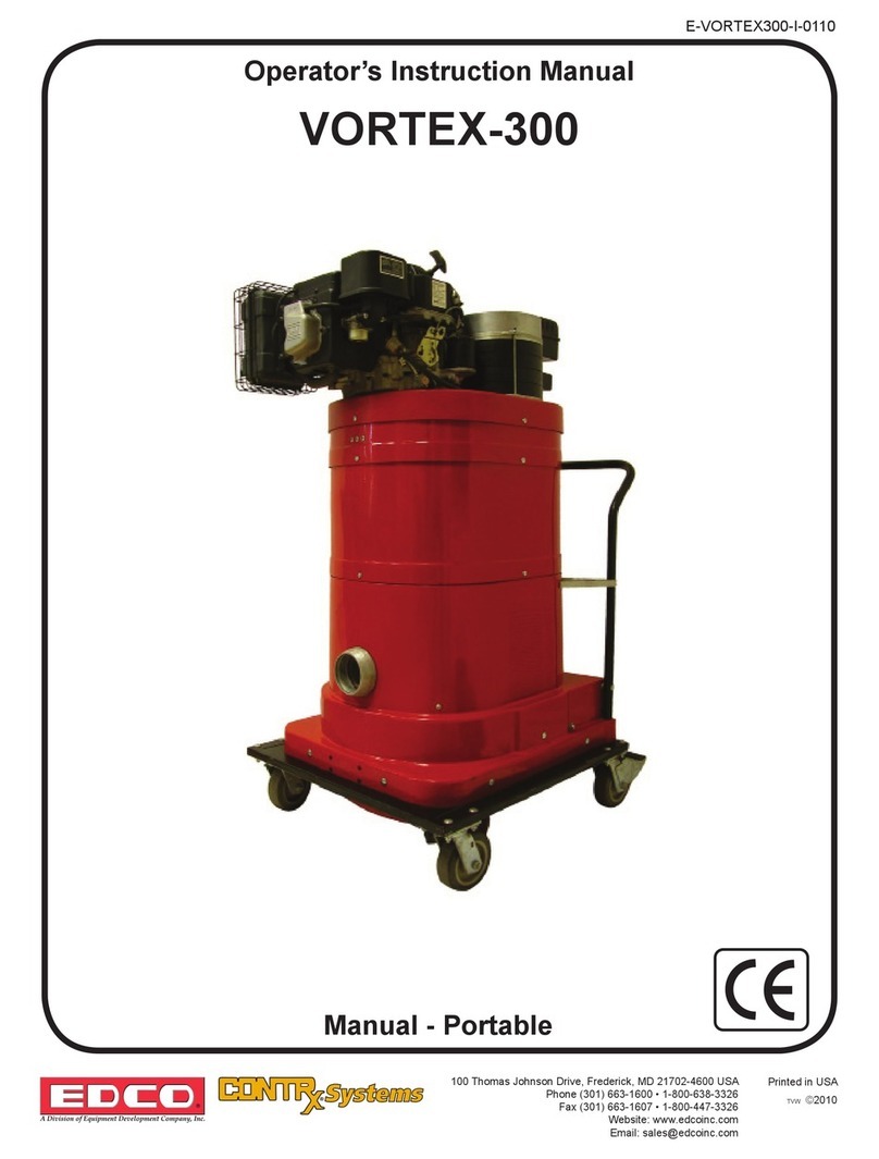
Edco VORTEX-300 Assembly instructions

Edco

Edco VORTEX-300 Assembly instructions

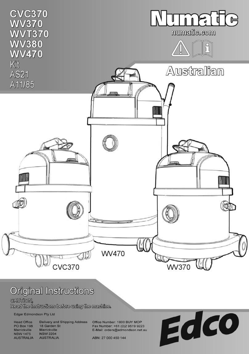
Edco Numatic CVC370 User manual

Edco

Edco Numatic CVC370 User manual

Edco SLURRY PRO VACUUM Assembly instructions

Edco

Edco SLURRY PRO VACUUM Assembly instructions

Edco VAC-100 User manual

Edco

Edco VAC-100 User manual

Edco Vortex 300 Datasheet

Edco

Edco Vortex 300 Datasheet

Edco VAC-290 Assembly instructions

Edco

Edco VAC-290 Assembly instructions

Edco WV 570 User manual

Edco

Edco WV 570 User manual

Edco Numatic HZC 390S-2 User manual

Edco

Edco Numatic HZC 390S-2 User manual

Edco Kit AH2 User manual

Edco

Edco Kit AH2 User manual

Edco GVE 370 User manual

Edco

Edco GVE 370 User manual

Popular Vacuum Cleaner manuals by other brands

Electrolux ZB2943 manual

Electrolux

Electrolux ZB2943 manual

Strend Pro K-408 instruction manual

Strend Pro

Strend Pro K-408 instruction manual

Philips FC6141 manual

Philips

Philips FC6141 manual

Hoover UH71230 Operating, and servicing  instructions

Hoover

Hoover UH71230 Operating, and servicing instructions

Bissell PROHEAT 2X REVOLUTION 1548 Series quick start guide

Bissell

Bissell PROHEAT 2X REVOLUTION 1548 Series quick start guide

Beko 01M-8813003200-2519-03 user manual

Beko

Beko 01M-8813003200-2519-03 user manual

LORD V2 user manual

LORD

LORD V2 user manual

Goldmaster VC-101 manual

Goldmaster

Goldmaster VC-101 manual

Beko VCS 5125 AR user manual

Beko

Beko VCS 5125 AR user manual

Windsor Senson SRXP15IA user manual

Windsor

Windsor Senson SRXP15IA user manual

Kärcher CV 66/2 Original instructions

Kärcher

Kärcher CV 66/2 Original instructions

Sirena sirena instruction manual

Sirena

Sirena sirena instruction manual

elvita CRD4550S user manual

elvita

elvita CRD4550S user manual

Parkside PAS 1200 F5 Operation and safety notes translation of the original instructions

Parkside

Parkside PAS 1200 F5 Operation and safety notes translation of the original instructions

Fieldmann FDU 2001-E manual

Fieldmann

Fieldmann FDU 2001-E manual

Redmond RV-UR356 user manual

Redmond

Redmond RV-UR356 user manual

Bobot WIN 701 user manual

Bobot

Bobot WIN 701 user manual

Hamron 006872 operating instructions

Hamron

Hamron 006872 operating instructions

manuals.online logo
manuals.online logoBrands
  • About & Mission
  • Contact us
  • Privacy Policy
  • Terms and Conditions

Copyright 2025 Manuals.Online. All Rights Reserved.