Eden Halls Greenhouses Silverline 86 Lean-To User manual
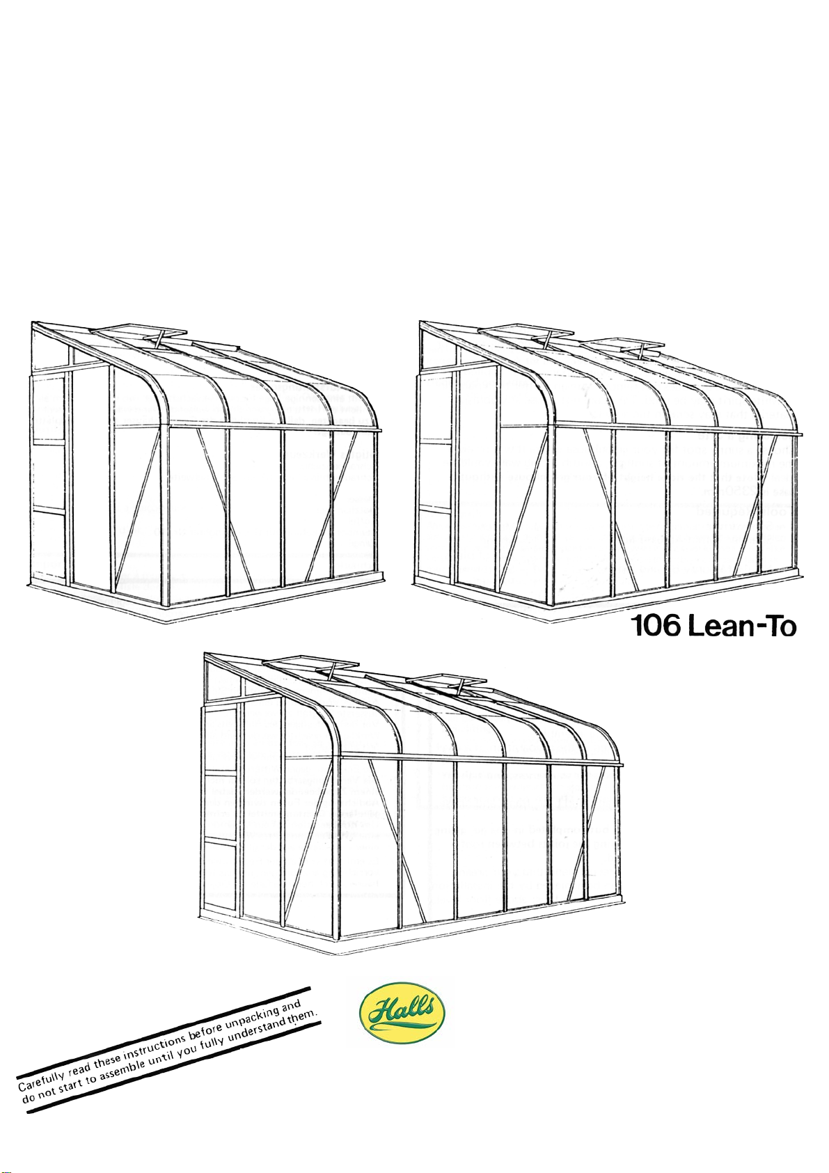
SILVERLINE LEAN TO
86, 106 and
126
86Lean-To
126Lean-To
Customer Service Department
Eden Halls Greenhouses Ltd.
Tel. 01242 676625 Option 1
mail@eden-greenhouses.com
30082013

Introduction
You now own a greenhouse that is believed to be amongst the best in value on the market, and by carefully
following these assembly instructions, it will give you years of trouble-free use. We hope you will find the following
hints and explanations useful.
Your greenhouse is made of aluminium because it is the best all-round material within the price limits the average
householder can afford. It will not swell, shrink, warp or rust. In service, it should become a dull whitish-grey colour,
sometimes with a slightly rough surface on the outside which forms a self-protecting layer.
If you have the horticultural glass, the small panes are less likely to crack due to movement of the greenhouse, are
easier to transport and cheaper to replace in the event of accidental damage.
The acrylic sheet has been selected for its flexibility to form the curved part of the roof, its weather resistance and
lasting clarity.
We recommend that you give your greenhouse all round protection by including it in your house insurance.
Maintenance
To keep your greenhouse clean, occasionally wash the glass and aluminium frame thoroughly with a mild detergent
solution. For difficult stains, white spirit may be used.
The acrylic may be cleaned using warm soapy water applied with a soft cloth. If this does not remove foreign matter
then paraffin or white spirit may be used. Take care not to use any abrasive material that may scratch the acrylic.
Selecting a Site
Choose a sunny spot for your greenhouse where it will receive a fair amount ofsunlight.
Note that the ridge height of your greenhouse without the base is2350mm.
Tools Required
1 – Screwdriver
1 – Spanner 10mm Across Flats
1 – No. 10 Masonry Bit and Drill
1 – Knife
1 – Spoon
1 – Pair of Pliers
1 – Spirit Level
Important
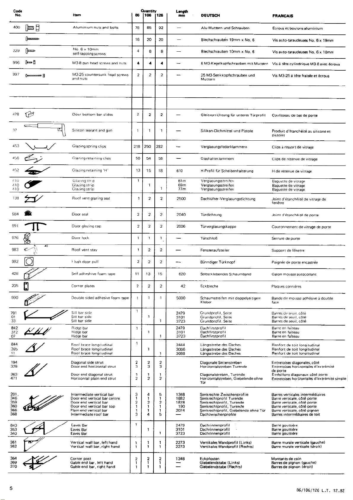
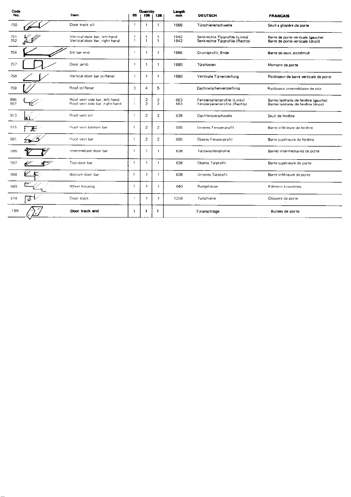
Before starting the assembly of your greenhouse, please check all the contents against the parts list. The parts for
each section are bundled together, so to avoid mixing them up, open each bundle separately. If anything is missing,
please contact Customer Service Dept., using the reply form included in these instructions.
1. Carefully read these instructions before unpacking and do not start to assemble until you fully understand
them.
2. Assistance will be necessary during assembly.
3. Considerable care should be taken in the preparation of a level and square base.
4. Before fixing frame to base, check for squareness and tighten all nuts and bolts. Weatherseal the join
between frame and base, frame and house and all other corner joints.
5. Glazing should not be hurried, but completed in one go, giving great care and attention to sealing the joints
between roof and panes with the sealant provided.
6. To minimise the condensation, werecommend that your greenhouse iswell ventilated. This can beachieved
by the installation ofa louvre vent. A louvre vent can only be fitted in the 106 and the 126 models.
7. It is recommended that a snow guard befitted tothehouse gutter above the greenhouse if there is a risk
of falling debris damaging the greenhouse.
1

1106 No. 6 x 16mm
self- tapping screws
1476
612
1774.5
1839
2

1633
PLEASE NOTE PART 00649 IS A REDUNDANT ITEM THAT IS NO LONGER REQUIRED
3

Base
You need a base for your greenhouse to ensure that it is level and rigid. To save time and trouble in laying a
traditional brick or concrete base, Halls can supply a simple-to-assemble prefabricated base as an optional extra.
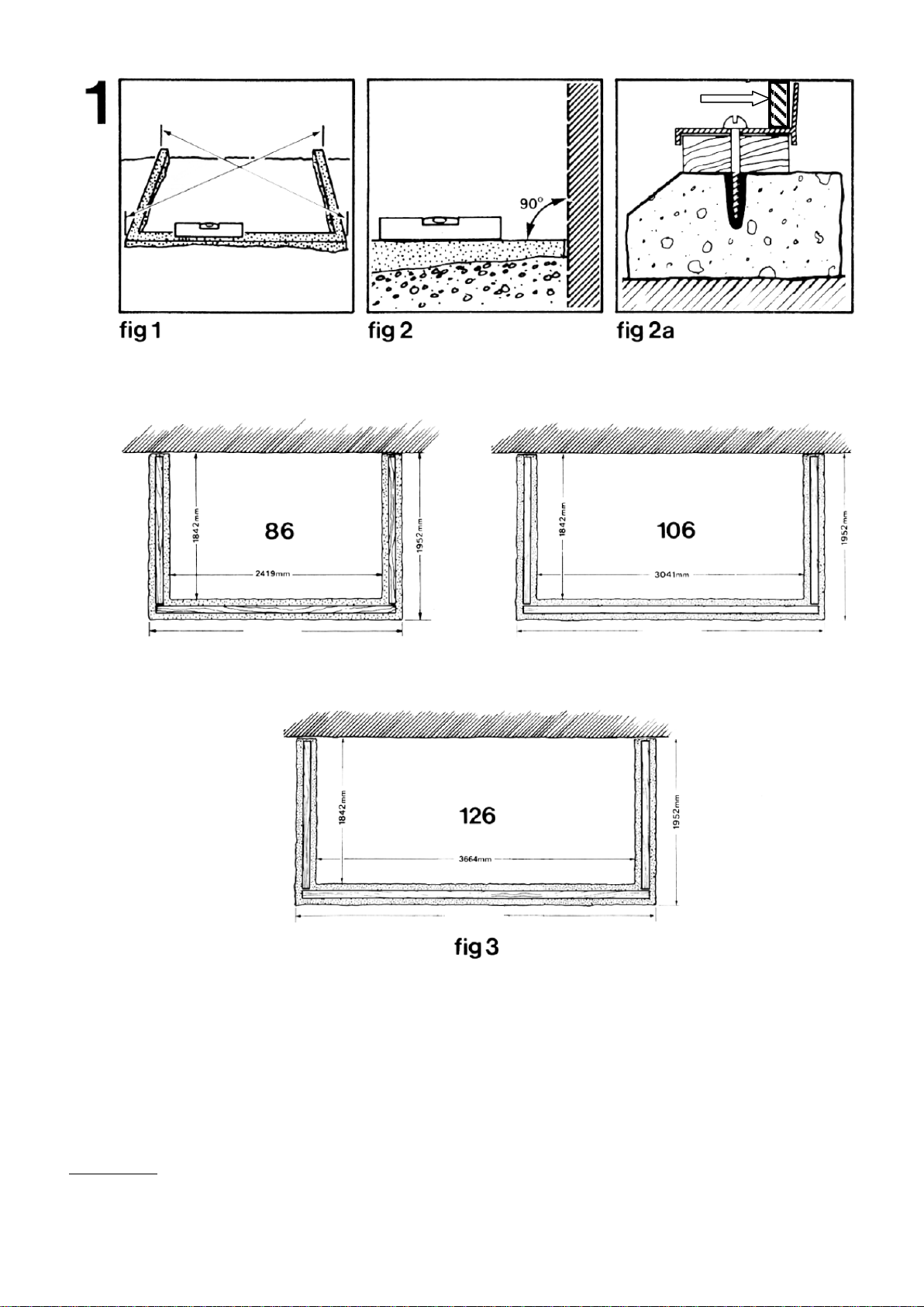
However, if you want to make your own base you should make it to the dimensions in fig. 3. It is most
important that the base is square and level so check that its diagonal measurements are equal as in fig. 1 and
that the angle between the wall and the base is 90ᵒas in fig. 2. Tanalised timber packing of not less than 12mm
thickness and not more than 30mm width should be made to fit the aluminium section, as shown in fig. 2a.
When the greenhouse has been assembled, it can be screwed to the base with no. 12 screws and rawlbolts (not
supplied) through the sill bar (not pre-drilled) in fig. 2a.
IMPORTANT
If you wish to erect your greenhouse on a solid concrete plinth, you should follow the outside dimensions in fig.
3. However it is important to avoid any possibility of water seeping under the base forming puddles. You should
ensure that the base slopes down towards the outside of the greenhouse. The timber packing will have to be
suitably tapered.
N.B. These diagrams are only if you are building your own base as opposed to buying the
prefabricated optional base, which is the easiest option.
GLASS
2635mm
3880mm
3257mm
4

PLEASE NOTE THE
GREENHOUSE MAY BE
SUPPLIED WITH EITHER
SQUARE NUTS OR
HEXAGONAL NUTS.
ABC
ED
5

2. Sides
Lay the parts coded in fig. 4 on the ground. All the illustrations in this section are viewed
from the inside. Join the sill bar(701/01/33)to theeaves bar (843/353/340)with the
intermediate vertical bars (201) – see details Band E.
IMPORTANT
Remember to slide one bolt into the groove of each intermediate vertical bar that is
crossed by a diagonal brace, in order to fix the centre of that brace, as in A.
The parts should be bolted with the square headed aluminium bolts and nuts provided, but
none of the bolts should be fully tightened until the greenhouse is completely assembled.
Bolt the two diagonal struts (194) over the top, as in A, Cand D.
Repeat with the other side.
6

MJH
GIKN
F
L
F
7

3. Plain Gable End
Note that the illustrations and photos are viewed from the inside. Left and right hand are
decided by standing outside the greenhouse.
The door can go on either end. Choose on which end the door should be, and this will
determine whether you build the left orright plain gable end.
Lay out the coded parts asbefore. Attach the corner plate (205) to the gable end bar (369
or 370) and the corner post (364)asin F.
Note that the plain side ofthe corner post should face inside the greenhouse and the bolt
head on the outside.
Bolt the end sill bar(756) to the corner post (364)asin G.Fix the plain end vertical glazing
bars (359 or 366)tothe gable barasinHand slide two bolts for the horizontal strut into
each vertical barbefore fixing the other ends tothe sill barasin I.
Attach the vertical wall bar (361 or 362) to the gable barand the sill asin Jand K.Bolt
the horizontal bars(471) to the bolt in the corner post and the loose bolts in the vertical
bars (359 or 366) as in Fand Mand bolt tothe vertical wall barN.
8

T
UR
O
S
QP
9
1 x Extra bolt
3 x Extra bolts
1 x Extra bolt
3 x Extra bolts

4. Door Gable End
Lay out the coded parts asbefore and bolt them together loosely using short bolts (400) in
the same order asthe plain gable end, except that the door track (974) should be fitted
BEFORE the vertical bar(346) as inT, Sand U.
Slide 2 bolts into (346)to attach thehorizontal (329)and vertical stiffener (758) as in O.
Match holes instiffener (758) with holes invertical wall bar (346) sothat the stiffener is
the correct way up.
Slide 4 bolts into vertical bar (359) to attach horizontal bar(329) and later the door
jamb (757).
The door lock, if required, can only be fitted on the INSIDE of the greenhouse.
Note that the diagonal strut (363)isfixed tothe sill bar (750) with the same bolt asthe
vertical bars as in Pand fix the other end as in Q.
Loosely fit a nut and bolt into the middle of the door track and then slide small vertical bar
(360)over the bolt head and tighten asinS.
Fix the other endofthe vertical bar to the gable end inthesame way asin R.
10

Plumbline
Spirit Level
Tanalised timber batten
VY
AA BB
Z
W
CC
11

5. Assembly
Note that all the photos and illustrations in this section are viewed from the inside, except fig. 7.
Join the two ends to the side section as in Zand AA. If you find that the corner plates are too rigid, slacken off
the bolts to allow more movement.
Mount the ridge bar (842 or 372 or 07) under the gable bars as in V. Fix ends of roof brace (844 or 365or 11) to
gable ends as in Y. Attach the curved intermediate roof bars (368) as in W. Note that picture Walso has the
roof stiffener attached.
The roof vent sills can only be positioned between two curved intermediate roof bars and should be fixed
loosely into place as in X. To slide the sill bars into place, first insert a bolt at either end of the sills with the bolt
heads uppermost. Then slide roof vent sill (913) very carefully into position from the bottom of the
intermediate roof bars, inserting the two bolts at either end of the sill into the grooves of the bars. Ease into
position detail X.
Before securing the intermediate roof bars (368) slide up THREE BOLTS in each to fit roof brace (844 or 365 or
11), roof stiffener (759) and to attach the bottom of (368) intermediate roof bars to the gutter.
Then use the bottom bolt in each intermediate glazing bar (368) to attach to the gutter. Then use the next
spare bolt to secure roof brace (844 or 365 or 11).
Now fit stiffeners (759) picking up spare bolts in intermediate roof bars, roof braces (844 or 365 or 11) as in CC
and roof vent sill, fixing the top to the bolt in the intermediate glazing bar (368).
Lift the frame onto the prepared base. Drop a plumbline from the top of the greenhouse to make sure that the
ends are perfectly vertical and parallel to the plumbline.
Lightly secure it with a masonry pin (not supplied) driven halfway through one of the securing holes at the top.
Mark the other fifteen or sixteen or seventeen (depending on size of greenhouse) securing holes on the wall
and remove the frame and the masonry pin.
Drill the holes with a no. 10 bit, and plug with no. 10 wall plugs.
At this stage, a 12mm deep bead of mastic (not supplied) should be thoroughly applied between base and sill.
Replace the frame onto the base.
Carefully drill securing holes through the timber batten and screw frame to wall. See detail in fig. 7.
Finally, secure the frame to the base. Ifyou have a prefabricated base (which can be bought as an optional
extra), follow the instructions that came with the base. Iffor anyreason they are missing, you can find them on
our website www.hallsgreenhouses.com on the Help andAdvice tab where it says “Base Instructions”.
If you have made your own base, you will need to drill through thesill of the greenhouse as in Section 1,fig. 2a.
Aperfect seal between the timber batten andwall may be obtained byusing a mastic or foam sealing tape
(not supplied).
IMPORTANT
Before finally tightening up all bolts, it is recommended that the sill, eaves, ridge and corner joints are sealed
using the silicon sealant (37) supplied.
This is achieved by releasing one joint at a time to ensure the silicon sealant penetrates each joint.
Finally, go round and tighten all nuts and bolts, but be careful not to tighten so firmly that you break the
threads on the bolts.
12
At this stage a 19mm x 16mm tanalised timber batten (not supplied) should be fitted between greenhouse and
wall fig. 7.

Spoon
Door Bottom Bar Slider 478
Bottom Horizontal Door Bar
N.B. Build the door before glazing.
DD
EE
FF
GG
VIEWED FROM INSIDE
HH
EXTERNAL
VIEW
INTERNAL
VIEW
GLASS
13
989
987
OUTSIDE

6a. Door
Lay the parts coded infig. 8 on the ground and attach the vertical door bars
(751 and 752) to the top door bar (987)using the No. 6x 19mm self-tapping
screws (401)provided as in FF. It is much easier to use an electric drill for this,
making sure the torque setting is correct, i.e. the lowest setting.
Make sure the holes between the bottom door barand the intermediate
bar are further apart than the top in order to fit the shorter top glass pane
B.This can be seen bylaying the two vertical door bars side by side to
match the holes.
Before fitting the intermediate door bar (986) check which side the door pull
should be on, depending on whether your door is on the left side or right side
of the greenhouse. For instance, if your door is on the right, the door pull
should be on the left.
Fit the intermediate door bar (986)and the bottom door bar (988)asin GG and
HH.
Fit the wheel-housing (989)to the top of the vertical door bars asin DD.
Fit the door bottom bar sliders (478)making sure the ears clip over the door
bar, using a spoon if necessary (to fit fully home) asinfig. 8.
Stick flush door pulls (992)into the holes in both sides ofthe intermediate
door bar asin EE.
14

610 x 305mm
Door glazing
Remember glass is fragile, handle with care using gloves. Stick double-sided adhesive foam strip (990)toboth vertical door bars
as in II, and tointermediate door bar as in Fig 9, making sure the aluminium surface is clean anddry.
The silicon sealant (37)istobeused toseal the joint between the glass andglazing retaining H (452)as in KK.
Lay the door frame flat onabench oronthe ground toglaze it. NOTE: Load silicon sealant cartridge into gun (supplied). Itis
important toback off the pressure after each application toprevent seepage ofsealant when not inuse. This can beachieved by
pressing thumb catch on back of gunasinJJ. Starting with the pane under the intermediate door bar,apply sealant (37)to the H
section and carefully push onto one pane of glass Cwith a rolling action as in LL,immediately wiping off excess with a clean dry
cloth. To achieve a good seal, all surfaces must beclean, dry andfreefrom oil which can beachieved byusing white spirit.
Place the other endof the glass onto the middle door bar making sure glass issquare,central and not overlapping onto the
channel in the vertical door bars asin II,. Peel off the backing tape from foam strip upthe vertical door bar only as far as the
height of the firstpane of glass andpush onto foam strip.
Push the 2nd pane of glass code C(for the bottom of the door) with a rolling action as in LL as far as possible into the H section
on the firstpane as in MM sealing as before making sure glass is square,central and not overlapping onto the channel in the
vertical door bars as in II.Peel off backing tape as before andpush into position. Immediately wipe off excess sealant from glass
using clean dry cloth.
Repeat glazing above intermediate door bar as before but notice that the top glass pane Bis shorter. Remove wheel housing to
fit the last pane of glass andcapping.
15

With the door flat on the ground or on a bench, starting at the bottom, push down fairly hard with the heel of your hand
working your way to the top, virtually flattening the capping (991) it will clip into both vertical door bars as in II.Cut the top
off level with the top of the glass with a hack saw. Then re-fit the door wheel housing. Slide door seal (984)into both vertical
door bars as in II and crimp bottom end ofdoor bars with pliers toprevent seal sliding down.
DOOR GLAZING WITH THE LONG PANE TOUGHENED GLASS AND OVERALL GLAZING FOR LONG
PANE TOUGHENED The glazing for the door with long pane toughened glass is the same as with horticultural except you
don’t have the (452) separators. Please see below.
16

OO
BF
RR
PP
INSIDE OUTSIDE
OUTSIDE INSIDE
17

6c. Door Hanging
Slide the door onto the door track, making sure the bottom door bar fits over the sill, as in
NN.
Adjust the bolts on the wheelhousing, so that the weight of the door is taken by the wheels,
but ensuring that the bottom door bar fits over the sill, so that it acts as a guide, and that
the vertical door bars do not catch on the track.
Tighten the bolts so that the door is held firmly and cannot wobble.
Note that the door lock is fitted on the INSIDE of the greenhouse so you may not need it.
Fit door lock (976) to door jamb (757) with the two screws (997) through the holes provided
in the door jamb as in PP.
Fit door jamb (757) to the door end vertical bar (359), noting the 2 small holes in end of the
door jamb are at the top and using the four bolts already in place, line up bolts with slots in
door jamb, push into place and tighten nuts as in QQ and RR.
Align the two holes in end of door track with the two holes on the top of the door jamb and
bolt into place as in OO using screw (996).
Fit door track ends (789) as in BF.
18

TOP
TOP
TOP
TOP
Gasket
Flat wooden
stick
Push
SS
XX
981
VV
Completed vent from inside
Completed vent from outside
YY
WW
19
OUTSIDE
TOP OF 913
This manual suits for next models
2
Table of contents
Other Eden Halls Greenhouses Greenhouse Kit manuals
Popular Greenhouse Kit manuals by other brands

Flower House
Flower House PlantHouse 2 Setup instructions

One Stop Gardens
One Stop Gardens 94241 Assembly and operating instructions

Harbor Freight Tools
Harbor Freight Tools 93920 Assembly instructions

Palram
Palram Americana 12'x12' Hybrid Glazing Assembly instructions

Vitavia
Vitavia VM0008-O Assembly instructions

Growers SOLUTION
Growers SOLUTION DAKOTA Installation