Safety and Care Advice
Important - Please read these instructions fully before starting assembly
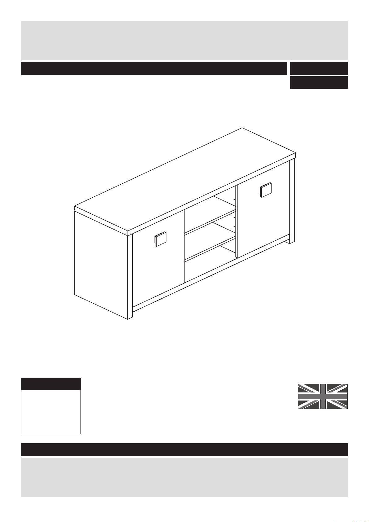
• Warning: This unit weighs
approximately 25kgs.
Please lift with care.
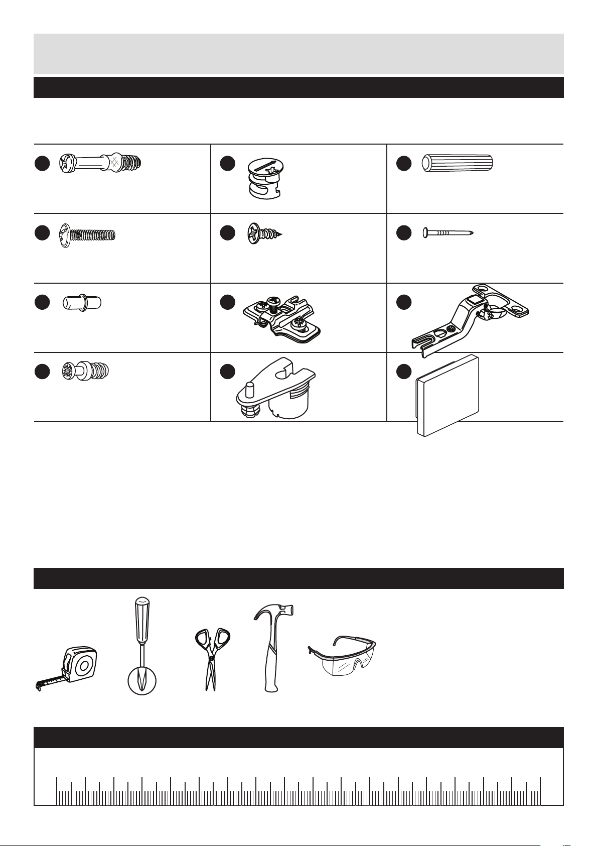
• Check you have all the
components and tools listed on
pages 2 and 3.
• Remove all fittings from the
plastic bags and separate them
into their groups.
• Keep children and animals
away from the work area, small
parts could choke if swallowed.
• Parts of the assembly will be
easier with 2 people.
• Make sure you have enough
space to layout the parts before
starting.
• Do not stand or put weight on
the product, this could cause
damage.
• Assemble the item as close to
its final position (in the same
room) as possible.
• Assemble on a soft level
surface to avoid damaging the
unit or your floor (use opened
out unit carton).
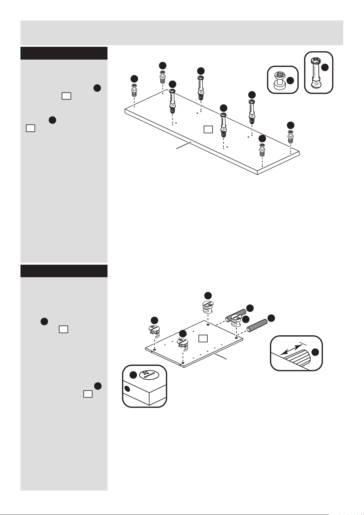
• We do not
recommend the
use of power
drill/drivers for
inserting screws,
as this could damage the unit.
Only use hand screwdrivers.
• Safety note: If there is any
chance of this unit being pulled
over by children etc. it is
recommended that the unit is
secured to a wall using suitable
fixings (not supplied).
• Dispose of all packaging
carefully and responsibly.
1
Care and maintenance
• Only clean using a damp cloth
and mild detergent, do no use
bleach or abrasive cleaners.
• From time to time check that
there are no loose screws on
this unit.
• This product should not be
discarded with household
waste. Take to your local
authority waste disposal centre.
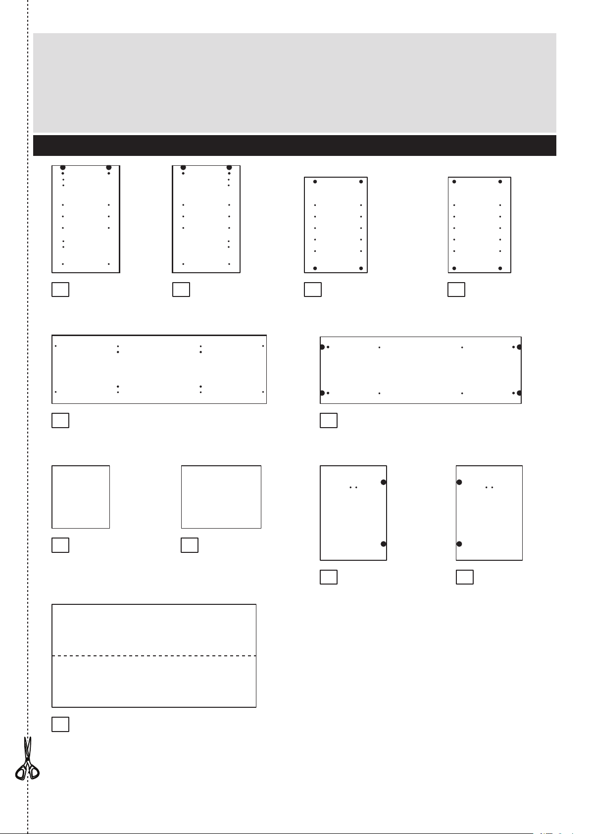
Note: If required the next page
can be cut out and used as
reference throughout the
assembly. Keep this page with
these instructions for future
reference.