EDI SSM-LE Series User manual

THIS MANUAL CONTAINS TECHNICAL INFORMATION FOR THE SSM-6LE, SSM-
6LEip, SSM-6LEC, SSM-12LE, SSM-12LEip, and SSM-12LEC SERIES SIGNAL
MONITOR.
REVISION: MARCH 2012
pn 888-1216-002
SSM-LE Series
NEMA TS-1
Enhanced Signal Monitor
Operations Manual

THE SSM-LE SERIES SIGNAL MONITOR IS DESIGNED AND MANUFACTURED
IN THE USA BY EBERLE DESIGN INC.
PHOENIX, ARIZONA
EDI IS CERTIFIED TO ISO 9001:2008 QUALITY SYSTEMS STANDARDS.
INFORMATION CONTAINED HEREIN IS PROPRIETARY TECHNICAL INFORMATION
OF EBERLE DESIGN INC. PUBLICATION, REPRODUCTION OR USE IN WHOLE OR
PART IS NOT PERMITTED EXCEPT UNDER TERMS AGREED UPON IN WRITING.
© COPYRIGHT 2012 EDI.
MAINTENANCE NOTE
THIS SIGNAL MONITOR UNIT HAS BEEN CAREFULLY INSPECTED
AND TESTED TO ENSURE PROPER OPERATION. IT IS
RECOMMENDED THAT THE MALFUNCTION MANAGEMENT UNIT
BE TESTED AT LEAST ANNUALLY TO ENSURE PROPER
OPERATION AND COMPLIANCE WITH FACTORY SPECIFICATIONS.

Table of Contents
Section 1 General............................................................................................................. 1
1.1 Description............................................................................................................. 1
1.2 Advanced Feature Overview .................................................................................. 1
1.2.1 Liquid Crystal Status and Field Display......................................................... 1
1.2.2 RMS Voltage Reporting ................................................................................ 1
1.2.3 ECcom Software Interface ............................................................................ 1
1.2.4 Flashing Yellow Arrow (FYA) Protected-Permissive Movement..................... 2
1.3 General.................................................................................................................. 2
1.4 Field Signal Terminals............................................................................................ 2
1.4.1 LEDguard®LED Field Signal Sensing............................................................ 3
Section 2 Standard NEMA Functions.............................................................................. 4
2.1 Conflict Monitoring.................................................................................................. 4
2.2 Red Fail Monitoring................................................................................................ 4
2.2.1 Red Enable Input.......................................................................................... 4
2.2.2 Walk Disable Option...................................................................................... 4
2.3 DC Voltage Monitoring........................................................................................... 4
2.3.1 +24Vdc Supply Monitoring............................................................................ 4
2.3.1.1 +24Vdc Monitor Inhibit Input ................................................................ 5
2.3.1.2 +24Vdc Monitor Latch Input................................................................. 5
2.3.2 Controller Voltage / Fault Monitor Input......................................................... 5
2.3.2.1 CVM Monitor Latch Input..................................................................... 5
2.3.2.2 CVM Log Disable................................................................................. 5
2.4 Power Failure Detection......................................................................................... 5
Section 3 Enhanced Features.......................................................................................... 7
3.1 Hardware Features................................................................................................. 7
3.2 Dual Indication Monitoring...................................................................................... 7
3.2.1 GY ENABLE Option...................................................................................... 8
3.2.2 Walk Disable Option...................................................................................... 8
3.3 Minimum Yellow Clearance Monitoring................................................................... 8
3.4 External Watchdog Monitoring................................................................................ 8
3.5 Program Card Absent Indication............................................................................. 8
3.6 Reset Input Detection............................................................................................. 9
3.7 Internal Diagnostics................................................................................................ 9
3.8 Real Time Clock / Calendar.................................................................................... 9
3.9 Display LED Test ................................................................................................... 9
3.10 Recurrent Pulse Detection.................................................................................... 9
3.11 Flashing Yellow Arrow Protected-Permissive Monitoring (FYA)...........................10
3.11.1 Basic FYA MODE ......................................................................................11
3.11.2 Compact FYAc MODE ...............................................................................12
3.11.3 FYA Channel Assignment Diagrams ..........................................................13
Section 4 ECcom Interface .............................................................................................14
4.1 EDI ECcom Monitor Reports .................................................................................14
4.1.1 General Data ...............................................................................................14
4.1.2 Current Status (S)........................................................................................14
4.1.3 Previous Fault (PF) Event Log .....................................................................14
4.1.4 AC Line (AC) Event Log...............................................................................14
4.1.5 Manual Reset (MR) Event Log.....................................................................14
4.1.6 Configuration (CF) Event Log.......................................................................15
4.1.7 Signal Sequence Event Log.........................................................................15
4.2 Ethernet LAN Port.................................................................................................15
Section 5 Installation.......................................................................................................16
5.1 Permissive Channel Programming ........................................................................16
5.2 Minimum Flash Time Programming.......................................................................16

5.3 SSM Switch Programming.....................................................................................16
5.4 Unit Option Programming......................................................................................17
5.4.1 GY ENABLE Option.....................................................................................17
5.4.2 LEDguard®Enable Option...........................................................................17
5.4.3 External Watchdog Enable Option ...............................................................17
5.4.4 Walk Disable Option.....................................................................................17
5.4.5 Controller Voltage Monitor (CVM) Latch Programming.................................17
5.4.6 24VDC Monitor Latch Programming.............................................................17
5.4.7 Log CVM FAULTS Option............................................................................17
5.4.8 Flashing Yellow Arrow Monitor.....................................................................17
Section 6 Front Panel Description..................................................................................18
6.1 Fault Status Display ..............................................................................................18
6.1.1 CONFLICT Indicator ....................................................................................18
6.1.2 RED FAIL Indicator......................................................................................18
6.1.3 CVM / WD Indicator .....................................................................................18
6.1.4 24V-1 Indicator.............................................................................................18
6.1.5 24V-2 Indicator.............................................................................................18
6.1.6 RP STATUS Indicator..................................................................................18
6.1.7 PROGRAM CARD Indicator.........................................................................18
6.1.8 DUAL INDICATION Indicator.......................................................................18
6.1.9 CLEARANCE Indicator ................................................................................19
6.1.10 Time and Date Indicator.............................................................................19
6.1.11 RE OFF Indicator.......................................................................................19
6.1.12 RX Indicator...............................................................................................19
6.1.13 TX Indicator ...............................................................................................19
6.1.14 PREV FAIL Indicator..................................................................................19
6.2 Field Status Display...............................................................................................19
6.3 LED Status Display ...............................................................................................19
6.3.1 POWER Indicator.........................................................................................19
6.3.2 FAULT Indicator...........................................................................................20
6.3.3 DIAGNOSTIC Indicator................................................................................20
6.4 Buttons..................................................................................................................20
6.4.1 RESET Button..............................................................................................20
6.4.2 MODE Button...............................................................................................20
6.4.3 INC Button...................................................................................................20
6.5 Display Modes.......................................................................................................20
6.5.1 Previous Fault Display Mode (PF Data Log).................................................20
6.5.2 AC Data Log Display Mode (AC Data Log)...................................................21
6.5.3 Configuration Display Mode.........................................................................21
6.5.4 Clock Set Display Mode...............................................................................21
6.6 Clearing the Data Logs..........................................................................................21
Section 7 Specifications .................................................................................................22
7.1 Electrical ...............................................................................................................22
7.1.1 Power Requirements....................................................................................22
7.1.2 AC Voltage Monitors....................................................................................22
7.1.3 Power Fail Monitor.......................................................................................22
7.1.4 DC Voltage Monitor......................................................................................22
7.1.5 Logic Inputs .................................................................................................22
7.2 Mechanical............................................................................................................22
7.3 Environmental.......................................................................................................22
7.4 Timing Functions...................................................................................................23
Section 8 Wiring Assignments .......................................................................................24
8.1 SSM-12LE Harnessing Connectors.......................................................................24
8.1.1 SSM-12LE Connector MS-A Pin Terminations.............................................24
8.1.2 SSM-12LE Connector MS-B Pin Terminations.............................................25
8.2 SSM-6LE Harnessing Connector...........................................................................26
8.2.1 SSM-6LE Connector MS-A Pin Terminations...............................................26

8.3 EIA-232 Connector................................................................................................27
8.3.1 EIA-232 Cable to a PC.................................................................................28
8.4 Ethernet LAN Port.................................................................................................28
8.4.1 Ethernet LAN Cable.....................................................................................28

SSM-LE Series
Operations Manual
Eberle Design Inc. Page 1
Section 1
General
1.1 DESCRIPTION
The SSM-LE series Signal Monitors consists of two models; the SSM-6LE, and SSM-12LE.
The SSM-6LE is a six channel unit and the SSM-12LE is a twelve channel unit. Both
models provide the same operational functions and features including advanced NEMA
Aplus@fault coverage, a full intersection liquid crystal display (LCD), comprehensive event
logging and signal sequence reporting, and true RMS voltage measuring and reporting. A
serial communications port is provided on all units that interfaces with the EDI ECcom
Signal Monitor Communications software running on a personal computer. Where not
specified otherwise, the information in this manual will apply to both models.
The SSM-LE Series Signal Monitor is a device used in a Traffic Controller Assembly to
accomplish the detection of, and response to improper and conflicting signals and improper
operating voltages in a Controller Assembly caused by malfunctions of the Controller Unit
(CU), load switches, or mis-wiring of the cabinet. The SSM-LE Series also provides error
sensing of two +24Vdc cabinet supplies and the controller power supplies via +24V
MONITOR I, +24V MONITOR II, and Controller Voltage Monitor (CVM) inputs respectively.
The Eberle Design SSM-LE Series is directly interchangeable with a standard NEMA
Signal Monitor and meets with or exceeds all specifications outlined in Section 6 (Conflict
Monitor) of the National Electrical Manufacturers Association (NEMA) Standards
Publication TS1-1989 R2005, Traffic Control Systems.
1.2 ADVANCED FEATURE OVERVIEW
1.2.1 LIQUID CRYSTAL STATUS AND FIELD DISPLAY
The SSM-LE Series uses a Liquid Crystal Display (LCD) to show monitor status and two
icon based LCDs to show field signal channel and fault status. This versatile display system
provides a service technician with both detailed information regarding cabinet status and
configuration, and at the same time an easily read field signal status display showing full
intersection status.
1.2.2 RMS VOLTAGE REPORTING
Input voltages are measured using a true Root Mean Squared (RMS) technique. A
dedicated Digital Signal Processor (DSP) RMS-Engine controls the analog to digital (A/D)
hardware which samples each AC input voltage a minimum of 32 times per cycle. The
RMS-Engine then calculates the true RMS voltage value producing accurate results which
are very insensitive to changes in frequency, phase, wave shape, and distortion.
1.2.3 ECCOM SOFTWARE INTERFACE
The field proven EDI ECcom Signal Monitor Communications software provides a laptop
computer or system interface to all information contained in the monitor. This includes
detailed status, voltages, configuration, as well as historical event logs, and five thirty
second Signal Sequence logs.
Event logs provide a historical record of previous fault data, ac line event data, monitor
reset events, and configuration programming change events. These logs are invaluable
when analyzing fault data to diagnose cabinet equipment malfunctions.
The Signal Sequence logs provide a graphical display of the signal states of all sixteen
channels for up to thirty seconds prior to the fault trigger point at 50 millisecond resolution.
The SSM-LE Series stores these signal records for the last five fault events.
The EDI ECcom software is available at no charge from the EDI web site at
www.EDItraffic.com.

SSM-LE Series
Operations Manual
Eberle Design Inc. Page 2
1.2.4 FLASHING YELLOW ARROW (FYA) PROTECTED-PERMISSIVE MOVEMENT
The SSM-LE Series is designed to monitor an intersection with up to four approaches using
the four section Flashing Yellow Arrow (FYA) movement outlined by the NCHRP Research
Project 3-54 on Protected/Permissive signal displays with Flashing Yellow Arrows. Two
cabinet configurations are supported depending on the number of load switches provided
and the capabilities of the Controller Unit. In both modes the SSM-LE Series has been
designed to provide the same broad fault coverage for the FYA approaches as it does for
conventional protected left turn phases including Conflict, Red Fail, Dual Indication, and
Minimum Yellow Clearance monitoring.
See section 3.11 for programming information.
1.3 GENERAL
The SSM-LE Series is configured as a 6 channel (SSM-6LE) monitor or a 12 channel
(SSM-12LE) when operated in a TS-1 type cabinet assembly. Each channel has the
capability of monitoring a Green, a Yellow, a Red, and a Walk field signal output at the
Terminals and Facilities field terminals.
A Program Card is provided for assigning permissive channels. The SSM-LE Series
detects the presence of conflicting Green or Yellow or Walk field signal inputs between any
two or more channels not assigned to be permissive on the Program Card. The RED
ENABLE input, when activated, enables the Red Fail Monitoring functions of the unit
causing the monitor to trigger when it detects the absence of voltage on all three (four) of
the field signal inputs of a channel. It also enables the Minimum Yellow Clearance
Monitoring function which verifies that the Yellow Change Clearance interval between the
end of an active Green signal and the beginning of the Red signal is proper. The monitoring
circuitry is capable of detecting either full wave or positive and negative half-wave
sinusoidal field signal inputs at the specified voltage levels.
When triggered by the detection of a fault condition which exists longer than the minimum
period defined by the NEMA Standards Publication TS1-1989 R2005 the SSM-LE Series
will enter the fault mode causing the OUTPUT relay to de-energize and two sets of contacts
on the OUTPUT relay to transfer. The cabinet assembly should be wired such that the
closure of the OUTPUT relay contacts will cause an automatic switching of the field signal
outputs from normal operation to flashing operation. The SSM-LE Series will then display
the appropriate fault status. The loss of AC LINE will not reset the fault mode of the
OUTPUT relay contacts. In the event of AC LINE loss the SSM-LE Series will retain the
status of all fault and channel indicators and will display the correct fault and channel status
upon restoration of AC LINE.
1.4 FIELD SIGNAL TERMINALS
A GREEN, YELLOW, or WALK field signal input will be sensed as active by the unit when it
exceeds the Green, Yellow, or Walk Signal Detect voltage threshold (Section 7.1.2) and a
field signal input will be sensed as inactive when it is less than the Green, Yellow, or Walk
Signal No-Detect voltage threshold (Section 7.1.2). Both positive and negative half wave
rectified inputs will be sensed.
A RED (DON’T WALK) field signal input will be sensed as active by the unit when it
exceeds the Red Signal Detect voltage threshold (Section 7.1.2) and a field signal input will
be sensed as inactive when it is less than the Red Signal No-Detect voltage threshold
(Section 7.1.2). Both positive and negative half wave rectified inputs will be sensed.
NOTE: When the circuit connected to the sensing input of an MMU exhibits high
impedance characteristics such as caused by dimmers, burned out lamps, low wattage
equipment, or no load, it may be necessary to place a low impedance device external to the
unit between the MMU input and AC NEUTRAL (See Sections 5.5.3.9 and 6.2.4 of NEMA
SSM-LE Series
Operations Manual
Eberle Design Inc. Page 3
Standards Publication TS2-2003 v02.06, Traffic Controller Assemblies With NTCIP
Requirements).
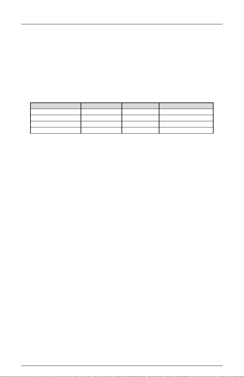
1.4.1 LEDGUARD®LED FIELD SIGNAL SENSING
The Eberle Design SSM-LE Series can be configured to use a technique called LEDguard®
that is designed to better monitor the characteristics of LED based signal loads (See
Section 5.4.2). Each field signal input is measured and compared to both a high threshold
and a low threshold value to determine On / Off status. This differs from conventional
standard NEMA operation where the active threshold is picked according to the color of the
field signal. Once the high and low On / Off thresholds (Section 7.1.2) have been
determined using the input RMS voltage, the individual fault monitor functions use the
appropriate threshold to determine if a fault condition exists.
LEDguard®
Green/Walk
Yellow
Red/Don’t Walk
Conflict
Low
Low
---
Red Fail
High
High
High
Dual Indication
Low
Low
Low
Clearance
Low
Low
High
A paper with further information on the EDI LEDguard®function can be found in the
Support section of the EDI web site, www.EDItraffic.com.

SSM-LE Series
Operations Manual
Eberle Design Inc. Page 4
Section 2
Standard NEMA Functions
2.1 CONFLICT MONITORING
When voltages on any conflicting channels are sensed as active for more than the Conflict
Fault time (7.4), the SSM-LE Series will enter the fault mode, transfer the OUTPUT relay
contacts to the Fault position, and display the CONFLICT status screen. The SSM-LE
Series will remain in the fault mode until the unit is reset by the RESET button or the
EXTERNAL RESET input. When voltages on any conflicting channels are sensed as active
for less than the Conflict No-Fault time, the SSM-LE Series will not transfer the OUTPUT
relay contacts to the Fault position.
The SSM-LE Series is fully programmable and requires the use of soldered wire jumpers
on an interchangeable Programming Card to define permissive channel pairs. See Section
5.1 for Programming Card details.
2.2 RED FAIL MONITORING
When voltages on all inputs (G, Y, R, W) to a channel are sensed as inactive for more than
the Red Fail Fault time (7.4), the SSM-LE Series will enter the fault mode, transfer the
OUTPUT relay contacts to the Fault position, and display the RED FAIL status screen. The
SSM-LE Series will remain in the fault mode until the unit is reset by the RESET button or
the EXTERNAL RESET input. When voltages on all inputs to a channel are sensed as
inactive for less than the Red Fail No-Fault time, the SSM-LE Series will not transfer the
OUTPUT relay contacts to the Fault position.
Red Fail Monitoring will be disabled when the RED ENABLE input is not active.
2.2.1 RED ENABLE INPUT
The RED ENABLE input will be sensed as active by the SSM-LE Series when it exceeds
the Red Enable Input threshold (Section 7.1.2). The presence of the proper operating
voltage at this input enables Red Fail Monitoring, Minimum Yellow Clearance Monitoring,
and Dual Indication Monitoring.
The main status screen will display “RE OFF” if the RED ENABLE input is not active.
2.2.2 WALK DISABLE OPTION
This option will modify the operation of Red Fail and Dual Indication Monitoring. When
enabled, the Red Fail and Dual Indication Monitoring function will not monitor the Walk field
outputs. Absence of signals on the Green, Yellow, and Red field outputs of a channel will
place the SSM-LE Series into the Red Fail fault mode causing the Output relay contacts to
transfer. Presence of active signals on the Walk outputs will not cause a Dual Indication
when concurrent with active Red or Yellow signals. This function is enabled by the Option
Switch called "WALK DISABLE". See Section 5.4.4.
2.3 DC VOLTAGE MONITORING
2.3.1 +24VDC SUPPLY MONITORING
The +24V MONITOR I and +24V MONITOR II inputs are provided for monitoring two
+24Vdc supplies in the cabinet assembly. Should loss of proper voltage occur at either of
these inputs, the SSM-LE Series will enter the fault mode, transfer the OUTPUT relay
contacts to the Fault position, and display the appropriate 24V-1 or 24V-2 status screen.
The SSM-LE Series will automatically reset the OUTPUT relay when the correct input
voltages are restored to both of these inputs. The SSM-LE Series will remain in the fault
mode for at least the time determined by the Minimum Flash programming.

SSM-LE Series
Operations Manual
Eberle Design Inc. Page 5
A voltage greater than the +24V Monitor input threshold (Section 7.1.4) applied to both of
the +24V MONITOR inputs will be sensed by the SSM-LE Series as adequate for operation
of the cabinet assembly. A voltage less than the +24V Monitor input threshold applied to
either of the +24V MONITOR inputs will be sensed as inadequate for proper operation.
When a +24V MONITOR input is sensed as inadequate for more than the +24V Monitor
Fault time (7.4), the SSM-LE Series will enter the fault mode and transfer the OUTPUT
relay contacts to the Fault position. When a +24V MONITOR input is sensed as inadequate
for less than the +24V Monitor No-Fault time, the SSM-LE Series will not transfer the
OUTPUT relay contacts to the Fault position. A +24Vdc failure during the programmed
Minimum Flash time or during a Power Failure will not cause a fault condition.
2.3.1.1 +24VDC MONITOR INHIBIT INPUT
A +24V MONITOR INHIBIT input is provided to inhibit the operation of the +24Vdc Monitor.
Application of a logic TRUE (low) state to this input will disable the operation of the +24Vdc
Monitor.
2.3.1.2 +24VDC MONITOR LATCH INPUT
An Option Switch is supplied on the front panel to allow +24Vdc failures to latch in the fault
condition until the unit is reset by the activation of the RESET button or the EXTERNAL
RESET input. See Section 5.4.5. A +24Vdc failure during the programmed Minimum Flash
time or during a Power Failure will not cause a latched fault condition.
2.3.2 CONTROLLER VOLTAGE / FAULT MONITOR INPUT
This input is to be connected to the CONTROLLER UNIT VOLTAGE MONITOR (CVM)
output from the Controller Unit. When the TRUE (low) state is absent for more than the
CVM Fault time (7.4), the SSM-LE Series will enter the fault mode, transfer the OUTPUT
relay contacts to the Fault position, and display the CVM status screen. When the TRUE
(low) state is absent for less than the CVM No-Fault time, the SSM-LE Series will not
transfer the OUTPUT relay contacts to the Fault position. The SSM-LE Series will
automatically reset the OUTPUT relay when the True (low) state is restored to the input.
The SSM-LE Series will remain in the fault mode for at least the time determined by the
Minimum Flash programming. A CVM failure during the programmed Minimum Flash time
or during a Power Failure will not cause a fault condition.
2.3.2.1 CVM MONITOR LATCH INPUT
An Option Switch is supplied on the front panel to allow CVM failures to latch in the fault
condition until the unit is reset by the activation of the RESET button or the EXTERNAL
RESET input. See Section 5.4.5. A CVM failure during the programmed Minimum Flash
time or during a Power Failure will not cause a latched fault condition.
2.3.2.2 CVM LOG DISABLE
If CVM events are not related to a malfunction condition and occur on a regular basis such
as Time of Day flash, the logging of these events can be disabled. See Section 5.4.7.
2.4 POWER FAILURE DETECTION
When the AC LINE voltage is below the minimum AC Line drop-out level (Section 7.1.2) for
the Power Fail Respond time (7.4), the SSM-LE Series will suspend all fault monitoring
functions, de-energize the OUTPUT relay, and de-energize the START relay. The POWER
indicator on the front panel will flash at a rate of 2Hz to indicate the low voltage status.
When the AC LINE voltage returns above the maximum AC Line restore level (Section
7.1.2) for the Power Fail Restore time (7.4), the monitor will resume normal operation and
the POWER indicator on the front panel will remain illuminated. After a 2.5 +_0.5 second
delay the START relay will be energized. After a programmable delay determined by the
Minimum Flash programming (see Section 5.2), the OUTPUT relay will be energized.

SSM-LE Series
Operations Manual
Eberle Design Inc. Page 6
This expanded operating voltage range for cabinet components allows the SSM-LE Series
to place the intersection into flash and return to normal operation in an orderly manner
when the AC LINE voltage is sufficient for proper operation. The SSM-LE Series should be
the first component in the cabinet to sense a low voltage condition and the last component
to sense a proper AC LINE operating voltage.
The AC LINE and AC NEUTRAL inputs are used to generate the internal voltage supplies
required to operate the monitor. AC NEUTRAL also serves as the return for all AC signals
including RED ENABLE. EARTH GROUND provides an independent connection to the
chassis of the unit and is isolated from AC NEUTRAL and LOGIC GROUND. LOGIC
GROUND is provided for inputs which are isolated from AC NEUTRAL (i.e. +24V Monitors,
CVM, CONTROLLER WATCHDOG, EXTERNAL RESET, and 24V MONITOR INHIBIT).
LOGIC GROUND may be tied to AC NEUTRAL if desired.

SSM-LE Series
Operations Manual
Eberle Design Inc. Page 7
Section 3
Enhanced Features
The following enhanced features are provided on the Eberle Design SSM-LE Series for
additional monitoring functions and to increase the reliability of the SSM-LE Series monitor
operation.
3.1 HARDWARE FEATURES
The SSM-LE Series is a dual microprocessor based unit. All monitoring functions and
features are firmware programmable which permits upgrades or modifications by simply
reprogramming the Flash memory device containing the firmware with the upgraded
version. Thus, most changes to the SSM-LE Series specifications may be accommodated
without modifying the hardware.
Since all critical timing functions are accomplished by the microprocessor, the quartz
crystal based accuracy results in very precise and repeatable measurements. This
accuracy is maintained on functions from timing fault conditions to implementing a unique
firmware based digital sampling and filtering algorithm. This algorithm is applied to all AC
field signals to help eliminate false detection in a "noisy" AC line environment.
Input voltages are measured using a true Root Mean Squared (RMS) technique. A
dedicated microcontroller RMS-Engine controls the analog to digital (A/D) hardware that
samples each AC input voltage at least 32 times per cycle. The RMS-Engine then
calculates the true RMS voltage value, producing accurate results which are very
insensitive to changes in frequency, phase, wave shape, and distortion. Voltage references
are temperature compensated for constant voltage levels within the operating temperature
range.
A nonvolatile EEPROM device is utilized to retain fault status information and event logs
through an AC Line power interruption. The correct fault indications will be displayed upon
restoration of AC Line power. This EEPROM device requires no battery back-up. The time
of day in the SSM-LE Series is stored in a battery-backed real time clock circuit. Should this
battery fail, only current time of day and date information will be lost. No monitor
configuration programming is stored under battery power.
3.2 DUAL INDICATION MONITORING
This monitoring function detects simultaneous input combinations of active Green and
Yellow, Green and Red, Yellow and Red, Walk and Yellow, or Walk and Red field signal
inputs on the same channel. When voltages on any two inputs of a channel are sensed as
active for more than the Dual Indication Fault time (7.4), the SSM-LE Series will enter the
fault mode, transfer the OUTPUT relay contacts to the Fault position, and display the DUAL
INDICATION status screen. The SSM-LE Series will remain in the fault mode until the unit
is reset by the RESET button or the EXTERNAL RESET input. When voltages on any two
inputs of a channel are sensed as active for less than the Dual Indication Fault time, the
SSM-LE Series will not transfer the OUTPUT relay contacts to the Fault position.
Dual Indication Monitoring may anticipate and prevent a possible conflicting signal display
in the intersection in the event that a proceed signal on the current phase hangs up and is
constantly detected as active. An open or no load condition (i.e., burned-out bulb) may be
also detected as an active signal depending on the output impedance characteristics of the
load switch (i.e. load switch leakage current), and may cause a Dual Indication Fault.
Dual Indication Monitoring will be disabled when the RED ENABLE input is not active. A set
of switches labeled “SSM” is provided on the SSM-LE series Signal Monitor front panel to
enable Dual Indication Monitoring on a per channel basis. See Section 5.3 for the
programming procedure.

SSM-LE Series
Operations Manual
Eberle Design Inc. Page 8
3.2.1 GY ENABLE OPTION
This monitoring function detects simultaneous inputs of active Green and Yellow field signal
inputs on the same channel. It can be used to monitor channels which have an unused Red
field signal input tied to AC LINE such as a five section signal head resulting in the SSM
switch in the Off position.
GY-Dual Indication Monitoring is enabled by the front panel option switch labeled GY
ENABLE. See Section 5.4.1. When the GY-Dual Indication Monitoring option is enabled, all
channels which have the front panel SSM switches OFF will be individually monitored for
simultaneous active Green and Yellow field signal inputs. All channels which have the front
panel SSM switches ON (i.e. enabled for Dual Indication Monitoring) will function as
described above in Section 3.2.
GY-Dual Indication Monitoring will be disabled when the RED ENABLE input is not active.
3.2.2 WALK DISABLE OPTION
This option will modify the operation of Red Fail and Dual Indication Monitoring. When
enabled, the Red Fail and Dual Indication Monitoring function will not monitor the Walk field
outputs. Absence of signals on the Green, Yellow, and Red field outputs of a channel will
place the SSM-LE Series into the Red Fail fault mode causing the Output relay contacts to
transfer. Presence of active signals on the Walk outputs will not cause a Dual Indication
when concurrent with active Red or Yellow signals. This function is enabled by the Option
Switch called "WALK DISABLE" on the front panel. See Section 5.4.4.
3.3 MINIMUM YELLOW CLEARANCE MONITORING
The SSM-LE Series will verify that the Yellow Change interval is at least the Clearance Fail
Fault time (7.4). The Yellow Change interval consists of the duration of time in which the
Yellow field signal input is active in a sequence from Green to Yellow to Red. When this
minimum interval is not satisfied the SSM-LE Series will enter the fault mode, transfer the
OUTPUT relay contacts to the Fault position, and display the CLEARANCE status screen.
The SSM-LE Series will remain in the fault mode until the unit is reset by the RESET button
or the EXTERNAL RESET input.
Minimum Yellow Change Monitoring will be disabled when the RED ENABLE input is not
active. A set of switches labeled “SSM” is provided on the SSM-LE series Signal Monitor
front panel to enable Clearance Monitoring on a per channel basis.
3.4 EXTERNAL WATCHDOG MONITORING
This function monitors an optional external watchdog output from a Controller Unit or other
external cabinet circuitry. The external source should toggle the EXTERNAL WATCHDOG
input logic state once every 100 msec. If the SSM-LE Series does not receive a change in
state on the EXTERNAL WATCHDOG input for the External Watchdog Fault time (7.4), the
SSM-LE Series will enter the fault mode, transfer the OUTPUT relay contacts to the Fault
position, and display the EXT WATCHDOG status screen. The SSM-LE Series will remain
in the fault mode until the unit is reset by the RESET button or the EXTERNAL RESET
input. A Power Failure will also reset the External Watchdog fault state of the monitor (see
Section 2.4).
This function is enabled by the front panel Option Switch called WD ENABLE (see Section
5.4.3). The EXTERNAL WATCHDOG input is harnessed to spare pin MSB-S on the front
panel B connector by the factory.
3.5 PROGRAM CARD ABSENT INDICATION
If the Program Card is absent or not seated properly in the edge connector, the SSM-LE
Series will enter the fault mode, transfer the OUTPUT relay contacts to the Fault position,

SSM-LE Series
Operations Manual
Eberle Design Inc. Page 9
and display the PROGRAM CARD status screen. The SSM-LE Series will remain in the
fault mode until the Program Card is correctly seated and the SSM-LE Series is reset by
the RESET button or the EXTERNAL RESET input.
3.6 RESET INPUT DETECTION
Activation of the front panel RESET button or the EXTERNAL RESET input will reset the
SSM-LE Series from the fault mode and cause the START relay to energize and the
OUTPUT relay to transfer to the no-fault state. Each activation of the RESET button or
EXTERNAL RESET input will cause a one time reset input to the unit. A continuously
activated RESET input will not prevent the SSM-LE Series from monitoring any fault
condition and/or transferring the OUTPUT relay contacts to the fault position. This function
prevents the Cabinet Assembly from being operated with the monitor unit disabled due to a
faulty RESET button or EXTERNAL RESET input.
3.7 INTERNAL DIAGNOSTICS
The SSM-LE Series is supplied with a resident series of self-check diagnostic capabilities
which monitor for correct operation of the SSM-LE Series both at power-up and
continuously during operation. When a diagnostic test fails, the SSM-LE Series will enter
the fault mode, transfer the OUTPUT relay contacts to the Fault position, and illuminate the
DIAGNOSTIC indicator. A Power Failure will reset the Diagnostic fault state of the monitor
(see Section 2.4). Due to the nature of these hardware/firmware failures, other fault
indicators that may be concurrently displayed with the DIAGNOSTIC indicator may not be
valid.
3.8 REAL TIME CLOCK / CALENDAR
A real time clock is provided on the SSM-LE series Signal Monitor to identify each event
occurrence with the time of day and date. This information is displayed and stored along
with the event status when the monitor is triggered by an event condition. The real time
clock is backed-up by a long life lithium energy cell and thus maintains accurate
timekeeping even during AC+ interruptions. This accuracy should remain within
approximately +_3 minutes per month.
The date and month are automatically adjusted for leap years. Daylight Savings Time
adjustments are made to the time of day on the Sunday specified by the start and end DLS
parameters. Daylight Savings Time parameters can be made using the EDI ECcom
software (see SET OPTIONS in the (EDI ECcom Software Operations Manual).
Setting the correct time of day and date is accomplished using the MODE and INC buttons
on the front panel (see Section 6.5.4) or by using the SET TIME command using the EDI
ECcom software.
3.9 DISPLAY LED TEST
The monitor will illuminate all front panel LED and LCD indicators for 500ms when a Reset
command is issued by the front panel RESET button or EXTERNAL RESET input. This
function provides a means to check the operation of all front panel indicators.
3.10 RECURRENT PULSE DETECTION
This error detection function supplements the normal Conflict, Dual Indication, and Red Fail
monitoring algorithms for sensing faults which are intermittent or pulsing in nature. The
RMS-Engine is designed to filter out short term transients commonly found on the electrical
service and provide noise immunity against false signal detections. The Recurrent Pulse
detection function is designed to respond to fault conditions which are intermittent in nature
and do not meet the continuous timing requirements of the normal detection algorithms, yet

SSM-LE Series
Operations Manual
Eberle Design Inc. Page 10
may still produce improper signal displays. These input conditions are differentiated by their
longer time constant and fault response times.
The figure below shows a simple example of a Recurrent Conflict fault. Channel 2 Green is
detected active due to a malfunction of the load switch which caused the output to “flicker”
On for 100 ms approximately every 200 ms. Because normal Conflict detection requires a
continuous fault of at least 350 ms typical, this event could go undetected. The Recurrent
Pulse detection algorithm will process these pulses into one event and trigger a Conflict
fault once the longer recurrent timing threshold is exceeded.
When triggered by a recurrent pulse fault condition, the SSM-LE Series will enter the fault
mode, transfer the Output relay contacts to the Fault position, and display the appropriate
CONFLICT, DUAL INDICATION, or RED FAIL status screen along with RP STATUS. The
unit will remain in the fault mode until reset by the Reset button or the External Reset input.
Fault response times will vary depending on the pulse width and frequency of the recurrent
inputs, but typically range from 1000 ms minimum to 10 seconds maximum.
3.11 FLASHING YELLOW ARROW PROTECTED-PERMISSIVE MONITORING (FYA)
The SSM-LE Series is designed to monitor an intersection with up to four approaches using
the four section Flashing Yellow Arrow (FYA) movement outlined by the NCHRP Research
Project 3-54 on Protected/Permissive signal displays with Flashing Yellow Arrows. For
monitoring purposes an FYA approach is logically defined as a four input “channel”
consisting of the solid Red Arrow, solid Yellow Arrow, flashing Yellow Arrow (permissive),
and solid Green Arrow (protected).

SSM-LE Series
Operations Manual
Eberle Design Inc. Page 11
- WARNING -
EDI does not provide any guidelines, warrants, or recommendations for the use of
protected/permissive left-turn phasing. The underlying assumption is that the traffic
engineer has decided that this form of protected/permissive control is the most
appropriate left-turn treatment, and all necessary considerations have been made.
Until official rulemaking action by the MUTCD has occurred, the operation and
functional parameters of the SSM-LE Series FYA and FYAc modes are subject to
change.
Two cabinet configurations are supported depending on the number of load switches
provided and the capabilities of the Controller Unit. A Flashing Yellow Arrow approach is
actually monitored using two physical channels of the SSM-LE Series. In the basic FYA
mode of the unit, one additional load switch is required for each FYA approach to be
monitored. Thus a cabinet providing four vehicle phases, four pedestrian phases, and four
FYA approaches would require sixteen load switches.
The compact FYAc mode requires the Controller Unit to remap the Yellow outputs of the
pedestrian load switches to drive the protected Green Arrow signals of the FYA
approaches. In this mode the cabinet can provide the four FYA approaches with an existing
twelve position back panel. Configuration settings are described in Section 5.4.8.
3.11.1 BASIC FYA MODE
The cabinet must be wired such that for each FYA approach, the solid Green protected
Arrow is driven by a load switch monitored on channels 1, 3, 5, and 7. The associated solid
Red Arrow, solid Yellow Arrow, and flashing Yellow Arrow (FYA Overlap phase) must be
driven by a load switch monitored on channels 9, 10, 11, 12 respectively. The SSM-LE
Series associates channel 1 with 9, channel 3 with 10, channel 5 with 11, and channel 7
with 12 when FYA monitoring is enabled for that respective approach.
If a channel pair is enabled for FYA operation, the SSM-LE Series will monitor the FYA
logical channel pair for the following fault conditions:
a. Conflict
i. Channel conflicts are detected based on the Permissive programming
jumpers on the Program Card for each channel. This operation
remains unchanged from normal Nema operation.
b. Red Fail
i. A Red Fail fault will occur if the solid Red Arrow AND solid Yellow
Arrow AND flashing Yellow Arrow AND solid Green Arrow all remain
inactive for the Red Fail fault response time. The fault icon () will be
displayed for both channels of the pair. The Red and Yellow inputs for
channels 1, 3, 5, 7 do not affect the Red Fail condition for the FYA
channels 9, 10, 11, 12.
c. Dual Indication
i. A Dual Indication fault will occur if any two or more of the solid Red
Arrow, solid Yellow Arrow, flashing Yellow Arrow, or solid Green Arrow
signal combinations are active simultaneously for the Dual Indication
fault response time. The fault icon () will be displayed for the FYA
channel 9, 10, 11, 12. The fault icon () will also be displayed for the
solid Green Arrow channel 1, 3, 5, 7 IF the solid Green Arrow was
active.
ii. If the Dual Indication function (SSM) is enabled for the solid Green
Arrow channels (1, 3, 5, 7) then a Dual Indication fault will occur if any
two or more of the Red, Yellow, or solid Green Arrow inputs (1, 3, 5, 7)
are active simultaneously for the Dual Indication fault response time.
d. Clearance
i. A Clearance fault will be detected if the channel pair sequences from
the solid Green Arrow (1, 3, 5, 7) to the solid Red Arrow (9, 10, 11, 12)

SSM-LE Series
Operations Manual
Eberle Design Inc. Page 12
without a minimum clearance time on the solid Yellow Arrow (9, 10, 11,
12). The fault icon () will be displayed for the FYA channel (9, 10, 11,
12).
ii. A Clearance fault will be detected if the FYA channel sequences from
the flashing Yellow Arrow (9, 10, 11, 12) to the solid Red Arrow (9, 10,
11, 12) without a minimum clearance time on the solid Yellow Arrow (9,
10, 11, 12). The fault icon () will be displayed for the FYA channel (
[9, 10, 11, 12).
iii. If the Clearance function (SSM) is enabled for the solid Green Arrow
channels (1, 3, 5, 7) then a Clearance fault will be detected if the
Green Arrow (1, 3, 5, 7) channel sequences from the solid Green
Arrow (1, 3, 5, 7) to the solid Red Arrow (1, 3, 5, 7) without a minimum
clearance time on the solid Yellow Arrow (1, 3, 5, 7). The fault icon ()
will be displayed for the solid Green Arrow channel (1, 3, 5, 7).
3.11.2 COMPACT FYAC MODE
The cabinet must be wired such that for each FYA approach, the solid Green protected
Arrow is driven by a load switch monitored on channels 9, 10, 11, and 12. The associated
solid Red Arrow, solid Yellow Arrow, and flashing Yellow Arrow (FYA Overlap phase) must
be driven by a load switch monitored on channels 1, 3, 5, and 7 respectively. The SSM-LE
Series associates channel 1 with 9, channel 3 with 10, channel 5 with 11, and channel 7
with 12, when FYA monitoring is enabled for that respective approach.
Note: Using the Compact FYAc mode allows a standard twelve position load bay to provide
the necessary signals without the addition of load switches for the FYA approaches. This
mode requires that the Controller Unit be capable of remapping the Protected Green Arrow
signal driver to the channel 9, 10, 11, and 12 Yellow load switch inputs. The cabinet must
be (re)wired such that the outputs of the Ped Yellow load switches are monitored by
channels 9, 10, 11, and 12 Green.
If a channel pair is enabled for FYAc operation, the SSM-LE Series will monitor the FYA
logical channel pair for the following fault conditions:
a. Conflict
i. Channel conflicts are detected based on the Permissive programming
jumpers on the Program Card for each channel. This operation remains
unchanged from normal Nema operation.
b. Red Fail
i. A Red Fail fault will occur if the solid Red Arrow AND solid Yellow
Arrow AND flashing Yellow Arrow AND solid Green Arrow all remain
inactive for the Red Fail fault response time. The fault icon () will be
displayed for both channels of the pair. The Red and Yellow inputs for
channels 9, 10, 11, 12 do not affect the Red Fail condition for the FYAc
channels 1, 3, 5, 7.
c. Dual Indication
i. A Dual Indication fault will occur if any two or more of the solid Red
Arrow, solid Yellow Arrow, flashing Yellow Arrow, or solid Green Arrow
signal combinations are active simultaneously for the Dual Indication
fault response time. The fault icon () will be displayed for the FYAc
channel 1, 3, 5, 7. The fault icon () will also be displayed for the solid
Green Arrow channel (9, 10, 11, 12) IF the solid Green Arrow was
active.
ii. If the Dual Indication function (SSM) is enabled for the solid Green
Arrow channels (9, 10, 11, 12) then a Dual Indication fault will occur if
any two or more of the Red, Yellow, or solid Green Arrow inputs (9, 10,
11, 12) are active simultaneously for the Dual Indication fault response
time.
d. Clearance

SSM-LE Series
Operations Manual
Eberle Design Inc. Page 13
i. A Clearance fault will be detected if the FYAc channel pair sequences
from the solid Green Arrow (9, 10, 11, 12) to the solid Red Arrow (1, 3,
5, 7) without a minimum clearance time on the solid Yellow Arrow (1, 3,
5, 7). The fault icon () will be displayed for the FYAc channel (1, 3, 5,
7).
ii. A Clearance fault will be detected if the FYAc channel sequences from
the flashing Yellow Arrow (1, 3, 5, 7) to the solid Red Arrow (1, 3, 5, 7)
without a minimum clearance time on the solid Yellow Arrow (1, 3, 5, 7).
The fault icon () will be displayed for the FYAc channel (1, 3, 5, 7).
iii. If the Clearance function (SSM) is enabled a Clearance fault will be
detected if the Green Arrow (9, 10, 11, 12) channel sequences from the
solid Green Arrow (9, 10, 11, 12) to the Red (9, 10, 11, 12) without a
minimum clearance time on the Yellow (9, 10, 11, 12). The fault icon
() will be displayed for the solid Green Arrow channel (9, 10, 11, 12).
3.11.3 FYA CHANNEL ASSIGNMENT DIAGRAMS
TS-1 FYA Modes
FYA Mode
FYAc Mode

SSM-LE Series
Operations Manual
Eberle Design Inc. Page 14
Section 4
ECcom Interface
4.1 EDI ECCOM MONITOR REPORTS
The EDI ECcom software package (Version 3.6.8 or greater is required) interfaces a
Computer or System to the SSM-LE Series. The ECcom program will display the Status
(S), Previous Fault (PF) event log, AC Line (AC) event log, Manual Reset (MR) event log,
Configuration (CF) event log, and Signal Sequence logs. All events are time stamped with
the time and date of the event.
Operation of the ECcom software package is described in EDI ECcom Software
Operations Manual and will not be covered in this manual. The EDI ECcom software is
available at no charge from the EDI web site at www.EDItraffic.com.
4.1.1 GENERAL DATA
Monitor ID#: a four digit (0000-9999) ID number may be assigned to the monitor.
Monitor Name: a thirty character name may be assigned to the monitor.
Time and Date: each event is marked with the time and date of occurrence.
Event Number: identifies the record number in the log. Event #1 is the most recent event.
4.1.2 CURRENT STATUS (S)
Fault Type: the fault type description.
Field Status: the current or latched RYGW field status and RMS voltages.
Cabinet Temperature: the current or latched temperature if the monitor.
AC Line Voltage: the current or latched AC Line voltage and frequency.
Control Input Status: the current or latched state and RMS voltage of the Red Enable input.
4.1.3 PREVIOUS FAULT (PF) EVENT LOG
Fault Type: the fault type description.
Field Status: the latched field status, RMS voltages, and fault channel status at the time of
the fault.
Cabinet Temperature: the latched temperature at the time of the fault.
AC Line Voltage: the AC Line voltage and frequency at the time of the fault.
Control Input Status: the latched state and RMS voltage of the Red Enable input.
4.1.4 AC LINE (AC) EVENT LOG
Event Type: describes the type of AC Line event that occurred.
Power-up: AC on, monitor performed a cold start
Brown-out: AC Line < drop-out level
Restore: AC restored from AC brown-out or AC interruption, no cold start
AC Line Voltage: the AC Line voltage at the time of the event.
4.1.5 MANUAL RESET (MR) EVENT LOG
The monitor was reset from a fault by the front panel Reset button or External Reset input
or non-latched fault clear.

SSM-LE Series
Operations Manual
Eberle Design Inc. Page 15
4.1.6 CONFIGURATION (CF) EVENT LOG
Program Card Matrix: the permissive programming for each channel
SSM Enable Switches: the switch programming for each channel
Option Switches: GY Enable, LEDguard, WD Enable, Walk Disable, CVM Latch Enable,
24V Latch Enable, CVM Log Disable
Control Inputs: 24V Inhibit
Configuration Check Value: the value of the 16 bit Check Value for the reported
configuration
4.1.7 SIGNAL SEQUENCE EVENT LOG
The Signal Sequence event log graphically displays all signal states and Red Enable state
for up 30 seconds prior to the SSM-LE Series fault trigger for the most recent five (5)
Previous Fault (PF) events.
4.2 ETHERNET LAN PORT
The optional Ethernet port must be configured with specific network parameters such as an
IP address, Subnet Mask, and Gateway address. The network port parameters are set or
changed using the EDI ECcom Signal Monitor Communications software. See the "EDI
ECcom Software Operations Manual" ETHERNET LAN SETTINGS Section 3.2.1.2 for
details.
This manual suits for next models
6
Table of contents
Other EDI Measuring Instrument manuals


Popular Measuring Instrument manuals by other brands


Rohde & Schwarz
Rohde & Schwarz GSM400-MS operating manual

Endress+Hauser
Endress+Hauser Liquiline System CAT860 operating instructions

Perfect Prime
Perfect Prime AQ380 instruction manual

Utility Solutions
Utility Solutions USJL-002 Operation manual

Landis+Gyr
Landis+Gyr Ultracold T550 Technical description

HT
HT HT98U user manual


