Edic CR2 User manual

CR2 COMPLETE
RESTROOM
RESTORATION
17 GALLON
PROFESSIONAL RESTROOM CLEANER
OWNER’S/OPERATOR’S MANUAL
PROUDLY DESIGNED AND MANUFACTURED BY
WWW.EDIC-USA.COM

UNPACKING YOUR NEW CR2:
When your machine is delivered, check the carton carefully
for signs of rough handling. If the machine is damaged, notify
the carrier immediately and request an inspection. Be sure
to keep the carton, packing inserts, packing lists and carrier’s
receipt until the inspector has veried your claim.
EDIC’s Liability ceases when the carrier picks up the ship-
ment. However, our customer service sta will be happy to
furnish any information needed in connection with the claim
and will attempt to expedite a resolution.
PLEASE READ BEFORE
OPERATING THE MACHINE:
Read the manual carefully and completely before attempting
to operate the unit. is manual has important information
for the use and safe operation of the machine. Keep this man-
ual handy at all times.
is machine has been engineered and manufatured to pro-
vide excellent performance and service. To ensure that your
equipment will continue to perform as intended:
• Maintain equipment regularly- following the suggested
maintenance schedule provided.
• Use only original EDIC parts when servicing.
• Operate equipment with care.
If additional information is needed, please contact EDIC at:
All information and specications printed in the manual are
current at the time of printing; however because of EDIC’s
policy of continual product development, we reserve the right
to make changes at any time without notice.
WARNING!
• e machine was designed for use on hard surfaces,
carpet, oor and upholstery extraction applications as per
instructions and recommendations written in this manu-
al. Any deviation from its proper use or purpose and the
consequential damage that may occur is the sole responsi-
bility of the end user.
• Disconnect the power cord from the outlet before ser-
vicing. Do not leave machine connected to an electrical
outlet when unattended.
• Do not immerse or use this machine in standing water.
Such use may cause electric shock.
• When using an extension cord, use only a 3-prong con-
ductor grounding cord-12 gauge wire or heavier.
• To avoid electric shock, do not expose the unit to rain or
snow. Store it indoors in a heated location only.
• Do not use the machine for dry vacuuming.
• Use defoamer at all times to prevent damage to the vacu-
um motor.
• Do not use water in excess of 130°F (54°C) in the solution
tank
• To prevent seal damage and chemical build-up to the
pump system, run clean water through the solution lines
aer each day’s use.
• Use only commercially available carpet cleaning solutions
and defoamer intended for use with machines of this type.
Do not use dyes, bleaches, ammonia, or other additives.
• e use of powdered cleaning solution, if not diluted
properly, may result in damage to the pump. Powdered
chemical is not recommended. If powdered chemicals are
used, premix in a separate container before placing in the
solution tank.
• Always read and understand your chemical’s MSDS (Ma-
terial Safety Data Sheet) before use.
• is equipment is not designed to handle or use combus-
tible/volatile substances such as gasoline or kerosene, in,
on, or near the machine. e use of such materials will
cause extreme hazardous condition.
• Do not expose machine to freezing temperatures.
• All repairs must be done by an authorized EDIC repair
station.
• Do not use replacement parts other than original EDIC
parts.
• Do not allow your spray stream to remain in one xed
location as surface damage may occur.
• Check that all spray nozzles are securely fastened. Loose
nozzles could be ejected from equipment at high speeds.
• Prevent burns by wearing gloves or using a barrier to
remove hot quick disconnects.
• is is not a toy. Keep away from children.
• Do not pull by the power or use power cord as a handle.
Always unplug by grabbing the plug and pulling, do not
unplug by pulling the power cord.
• Inspect cord for damage. Do not use damaged cords. Con-
nect only to properly grounded outlets.
• Keep hair, ngers, loose clothing, and body parts away
from moving parts and openings.
• Turn o all controls before disconnecting machine
• Use caution with ejected liquid or chemicals. High pres-
sures and temperatures could be hazardous to nearby peo-
ple or surroundings.
FAILURE TO COMPLY WITH THE ABOVE
WARNING INSTRUCTIONS WILL
VOID THE WARRANTY.
2
GROUNDING INSTRUCTIONS:
is piece of equipment must be grounded. Should an
electrical malfunction occur, grounding provides a path
of least resistance for electrical current- reducing the risk
of electric shock. is piece of equipment is furnished
with a cord that has a grounding conductor and ground-
ing plug. e grounded plug must only be plugged
into an appropriate outlet that is properly installed and
grounded in accordance with all local codes and ordi-
nances.
WARNING:
Connecting the equipment to an improperly grounded
outlet can result in an increased risk of electric shock. A
qualified electrician should be consulted if you are un-
sure that the outlet is properly grounded. Do not modify
the plug provided with the equipment. If it will not fit
the outlet, have a proper outlet installed by a qualified
electrician.
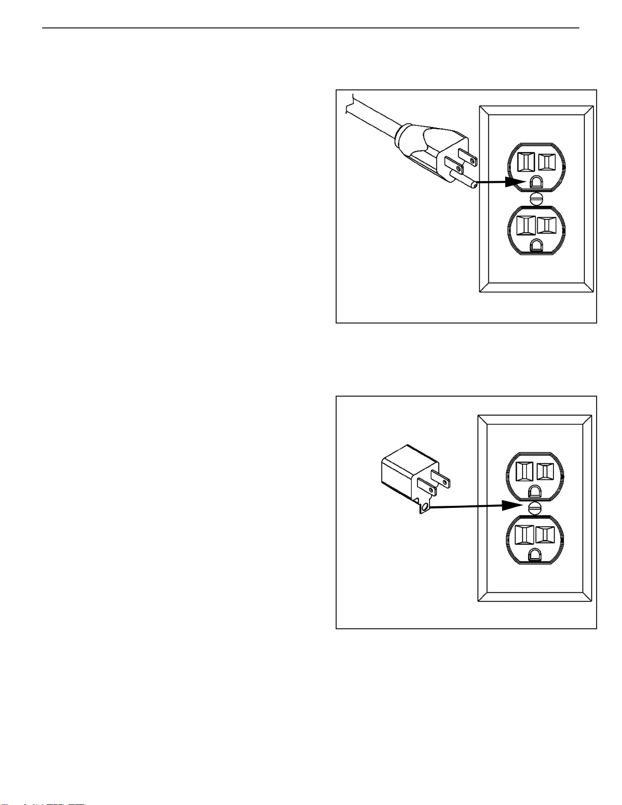
is appliance is designed for use on a 120-volt circuit.
e grounding plug provided looks like the plug illus-
trated in Figure 1.
A temporary adapter such as the one illustrated in
Figure 2 may be used to connect this plug to a 2-pole
receptacle (see Figure 2), if a properly grounded outlet
is not available. Temporary grounding adapters should
only be used until a properly grounded outlet (see
Figure 1) can be installed by a qualified electrician. e
green-colored rigid ear, tab, or similar, extending from
the adapter must be connected to a permanent ground
such as a properly grounded outlet box cover. Whenever
an adapter is being used, it must be secured by a metal
screw. ese temporary grounding adapters are not
approved for use in Canada.
Replace the plug if the grounding pin is damaged or
broken.
e Green (or Green/Yellow) wire in the cord is the
grounding wire. When replacing a plug, this wire must
be attached to the grounding pin only.
Extension cords connected to this machine should be
12 gauge, three-wire cords with three-prong plugs and
outlets. DO NOT use extension cords more than 25 feet
(7.6 m) long.
Fig. 1
Fig. 2
3
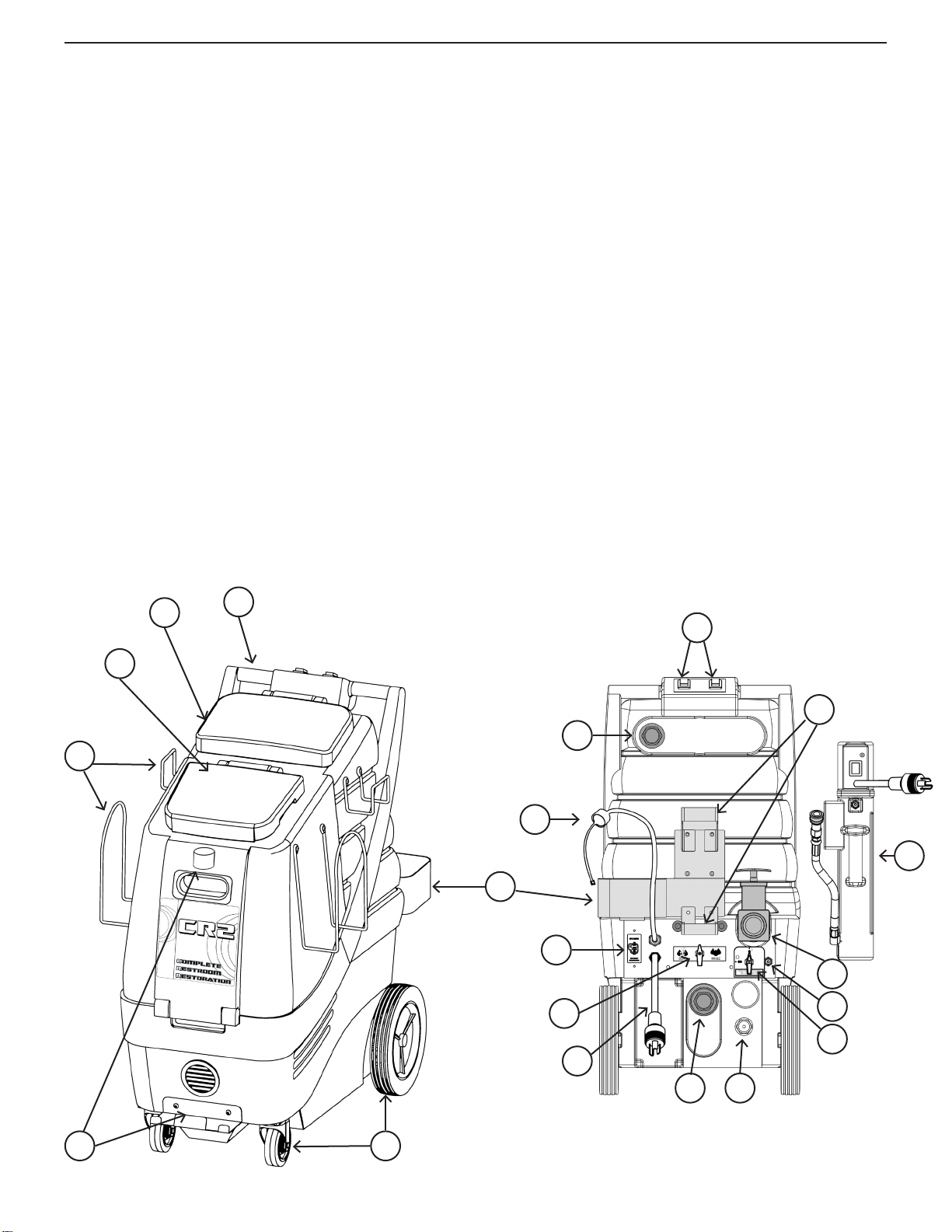
1. Handle- Used to maneuver and position the CR2
2. Recovery tank lid- Allows access to recovery tank
and creates a seal to ensure suction
3. Solution tank lid- Allows access to the solution tank
and prevents external contamination of solution tank
4. Accessory racks for hoses, cords, tools etc.- One large
rack and one small rack on each side of the machine.
4 total
5. Wand storage bracket and velcro strap- Allows the
operator to secure a wand attachment to the machine
for ease of transport
6. Non-marking front 4” locking casters and rear 10”
wheels
7. Recovery/vacuum hose inlet barb- connect your
recovery vacuum hose to this barb
8. Feed hose line for chemical with threaded bottle cap-
secures the feed hose line to the chemical bottle
9. Bottle holder for chemical feed system- Holds up to a
one gallon chemical bottle
10. GFCI breaker- Interrupts and disables the electrical
system if a ground leak is detected.
11. Chemical dispensing valve- Select between chemical
and no chemical by turning to le or right as marked
12. Male twist lock pigtail- Connects to 50 cord
13. Exhaust port hose barb- Used to connect to hose
with blower attachment.
14. Pressure regulator- Decrease pressure by turning
counter-clockwise or increase pressure by turning
clockwise
15. Priming/pressure relief valve- Prime system in the
event of air lock. Relieves pressure in the event of
pressure lock
16. Solution line Q.D.- Pressurized connection for solu-
tion line
17. Recovery tank dump valve- Pull up to open
18. Accessory Heater (Available separately)
19. Heater mounting brackets- for accessory heater
20. Switch box- one switch marked “PUMP” and one
switch marked “VACUUM”. Switches light up when
powered on.
3
21
4
8
65
9
10
11
12
13 14
15
16
17
18
20
7
19
4
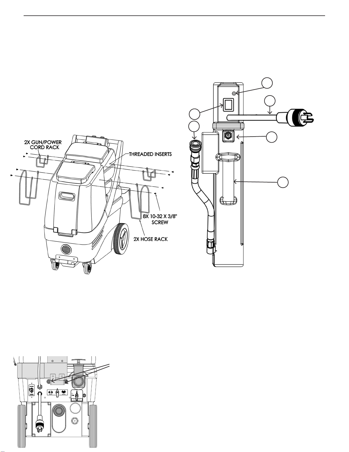
Assembling the accessory racks:
e CR2 is shipped with the accessory racks and hard-
ware in the solution tank. When you receive your CR2,
it is necessary to secure the racks to the body. e only
tool required to complete this action is a Phillips head
screwdriver.
e CR2 comes equipped with threaded inserts pre-in-
stalled in the body. e two larger racks are installed
toward the front of the machine- one per side and the
two smaller racks are installed toward the rear, also one
per side.
Installing an accessory heater:
If a 600HR Heat “n” Run heater system has been pur-
chased for the CR2, use the following illustration to
familiarize yourself with the heater.
Opening the machine:
is unit can be opened by simply removing two bolts
located on the back of the machine. e unit will open
forward by liing up on the handle. If you need to open
the unit further, you may release the vacuum hose going
from the base of the vacuum plate to the bottom of the
recovery tank by loosening the hose clamp.
2 BOLTS
1
2
4
5
3
6
1. Power switch- Lights up when switched to power
“ON”
2. “IN” hose connect to male Q.D. (Number 16 on page
4)
3. Lamp will turn on anytime the heat element is ac-
tivated. Lamp will turn o any time max temp is
reached.
4. Male twist lock Pigtail- connects to 50 cord
5. “Out” male Q.D.- Connect to your 35 solution line
6. Handle
5

How to use an accessory heater:
1. Mount the Heater by lining up the two “legs” to the
two mounting brackets on the rear of the machine.
(19 on page 4)
2. Fill the solution tank of your CR2 with sucient
water for the task at hand
3. Connect your heater’s in hose (#2 on page 5) to #16
on page 4
4. Connect your 35 solution hose to #5 on page 5
5. Connect your 35 vacuum hose to number 7 on
page 4.
6. Connect your wand or upholstery tool to the end of
your 35 solution hose
7. Connect the power cord on the machine and the
power cord to the heater to two separate plugs on
two separate circuits.
8. Turn the priming/pressure relief valve (15 on page
4) 45 degrees to the le to the open position
9. Turn the pump to the on position
10. Allow pump to prime
11. Close priming valve
12. Turn heater on and allow up to 3 minutes for the unit
to heat up.
You will know the heater is ready for use once the green
lamp shuts o the rst time. Once you start cleaning car-
pet, the green lamp will turn on and o throughout your
job as the thermostats regulate the temperature.
Note: e heater is mainly to be used for carpet cleaning.
While the heater may provide some heat during chem-
ical application, it is unlikely to reach desired tempera-
tures during continous spray conditions.
Installing metering tips for the Chemical feed
system:
Remove the semi-clear hose from the bottle cap (8 on
page 4). Select the appropriate metering tip for the dilu-
tion required and push it into the tube on the bottle cap.
Metering tip color guide:
Tan 1.25oz/Gal
Turquoise 2.00oz/Gal
Pink 3.00oz/Gal
Brown 4.00oz/Gal
White 5.00oz/Gal
Chemical feed system and hard surface clean-
ing:
e chemical feed system is designed to deliver accu-
rate chemical dilution for touchless surface cleaning.
e chemical feed system is activated by low pressure
spraying and is not suited for chemical dispensing while
performing carpet cleaning. To clean hard surfaces:
1. Fill the solution tank of your CR2 with sucient
water for the task at hand
2. Connect hoses and accessory pressure gun
3. Select the appropriate tip and install on the cap of
the chemical feed (number 8 on page 4)
4. Place a bottle into bottle holder (number 9 on page
4)
5. Take the feed tube attached to the cap (number 8 on
page 4) and place it inside the bottle.
6. Take the cap from number 8 on page 4 and thread it
onto the bottle of chemical to secure it in place
7. Turn the chemical dispensing valve (11 on page 4)
to the le to the word “SOAP”
8. Chemical will only draw in the “Low pressure”
setting of your pressure gun. To activate the Low
pressure setting, pop the collar of the gun out.
9. While in the low pressure setting, apply chemical to
the walls and xtures starting from the lowest point
to the highest.
10. Spray the oor as you make your way out of the
room
11. Allow the chemical to dwell according to the chemi-
cal manufacturers recommendations
12. You may use the brush on your squeegee/brush
wand to agitate particularly soiled areas
13. When you are ready to rinse away chemical, simply
turn the Chemical dispensing valve to the right to
the word “RINSE”
14. Set your pressure gun to “high” pressure by pulling
the collar back in. Rinse surfaces starting from the
top down.
15. See “Recovering liquid” for nal steps
6

Recovering liquid:
e CR2 is equipped with two dedicated tools for liquid
recovery: the squeegee/brush wand and the Gulper tool.
Other accessories are available for the CR2.
1. Connect recovery vacuum hose to the recovery inlet
barb (number 7 on page 4)
2. Turn the vacuum switch (19 on page 4) into the on
position
3. Using either the squeegee/brush wand or the Gulper
tool, extract the liquid from the surface.
4. Monitor the levels in the recovery tank and empty
as necessary. Use defoamer to ensure your vacuum
motor does not take in uid
Using the blower hose:
e CR2 has a hose barb (13 on page 4) tted to the vac-
uum motor’s exhaust. By attaching a hose to this tting,
the energy from the exhaust is redirected and allows the
operator to use the accessory hose as a blower.
Convenient for:
• Blowing uid o countertops and walls onto the
oor
• Drying Faucets and other xtures
Cleaning carpet or upholstery:
e CR2 can be used as a cold or hot water extractor.
If you do not have an accessory heater, then perform e
steps below 1-12. If you do have a heater, read the heater
steps on page 6 and continue at step 10 below.
1. Prespray the area of carpet to be cleaned
2. Connect your solution line
3. Connect your recovery vacuum hose
4. Connect your wand or upholstery tool to the solu-
tion and vacuum hoses
5. Fill the solution tank of your cr2 with water
6. Turn the pump switch to the “on” position
7. Turn the priming valve to the le to the open posi-
tion if pump needs to be primed
8. Allow pump to prime
9. Close the Priming valve
10. Turn on the vacuum motor
11. Spray on the backstroke and do a dry stroke when
pushing forward.
12. Overlap your previous path slightly when you pull
back.
Maintenance:
• Use only chemicals safe for extractors
• Adhere to the appropriate mix ratios for all chemi-
cals
• Do not add chemical to the solution tank- use the
chemical feed system
• For optimal performance, it is suggested that the
operator ush the system aer every job or at the end
of the day.
• Pump seals and valves may need to be replaced at the
1000 hour mark if a loss in pressure is noted
e pressure regulator may require servicing should a
pressure drop be noted
Daily:
• Flush chemical lines
• Check and clean vacuum lter
Wee kly :
• Check and clean solution lter
• Check for obstructions in vacuum pathways
Quarterly:
• Check pump, plumbing and ttings for leaks
• Check power cords and hoses for tears
7


Other manuals for CR2
1
Table of contents
Other Edic Cleaning Equipment manuals


Popular Cleaning Equipment manuals by other brands

Profigold
Profigold PROC9001 user manual

Konig & Meyer
Konig & Meyer 80310 instructions

PREMIER AUTOMATION
PREMIER AUTOMATION HydroCleaner Operator's manual

HydraMaster
HydraMaster Boxxer 318 owner's manual

Clarus Technologies
Clarus Technologies PCS-35 Operator's manual

Stratasys
Stratasys WaveWash 55 user guide

unGer
unGer Hydro Power Ultra UNP01 operating instructions

Victrola
Victrola VA-55 instruction manual

Elma
Elma Elmasonic xtra ST operating instructions

Elma
Elma Elmasonic Select Translation of the original manual

Westfalia
Westfalia 92 12 79 Original instructions

Dane Technologies
Dane Technologies QuicKLEEN Owner's manual & operating instructions


