PREMIER AUTOMATION HydroCleaner User manual

DOC: PASU042820-1
HydroCleaner
OPERATOR’S MANUAL
WARNING:
Improper use and/or failure to follow instructions may result in serious injury. Carefully read all instructions
before use. Never spray flammable, caustic, acidic, chlorine, bleach, petroleum, non-water based, or
other corrosive solutions or heat, pressure, or gas producing chemicals. ALWAYS follow chemical
manufacturer’s SDS instructions.

Page 2 of 13
TABLE OF CONTENTS
1. MAIN COMPONENTS 3
1.1 HYDROCLEANER FIGURES 3
1.2 MAIN COMPONENTS LIST 4
2. PRODUCT SPECIFICATIONS 4
3. SAFETY INFORMATION 5
4. OPERATION 6
4.1 BEFORE USE CHECKLIST 6
4.2 FILLING THE TANK 6
4.3 OPERATING PROCEDURE 7
4.4 SPRAY ADJUSTMENT 8
5. CARE INSTRUCTIONS 10
5.1 EMPTYING THE TANK 10
5.2 RINSING THE SYSTEM 11
5.3 STORAGE 11
6. WARRANTY 13
7. DISCLAIMER 13
8. LIMITATION OF LIABILITY 13
TABLE OF FIGURES
FIGURE 1.1.1 HydroCleaner Overall 3
FIGURE 1.1.2 HydroCleaner Side View 3
FIGURE 1.1.3 HydroCleaner w/Front Access Panel Removed 3
FIGURE 1.1.4 Pump Front View 3
FIGURE 1.1.5 Pump Side 3
FIGURE 1.1.6 Spray Gun 3
FIGURE 4.2.1 Tank Pressure Gauge 6
FIGURE 4.2.2 Tank Open 7
FIGURE 4.2.3 Tank Drain Valve Closed 7
FIGURE 4.4.1 Spray Gun Liquid and Direction Adjust 8
FIGURE 4.4.2 Spray Gun Pattern and Pressure Adjust 9
FIGURE 4.4.3 Tank Pressure Regulator 9
FIGURE 4.4.4 Pump Pressure Regulator 10
FIGURE 5.1.1 Tank Drain Valve Opened 10
FIGURE 5.1.2 Drain Button 11
FIGURE 5.3.1 Pump Drain Plug 12

Page 3 of 13
1. MAIN COMPONENTS
1.1 HydroCleaner Figures:
FIGURE 1.1.1 HydroCleaner Overall
A
B
FIGURE 1.1.5 Pump Side
View
U
FIGURE 1.1.4 Pump Front View
Q
R
P
T
S
FIGURE 1.1.3 HydroCleaner w/Front
Access Panel Removed
G
H
I
J
K
M
L
N
G
O
FIGURE 1.1.6 Spray Gun
W
X
Z
AA
Y
B1
B2
V
FIGURE 1.1.2 HydroCleaner Side View
C
D
E
F

Page 4 of 13
1.2 Main Components List:
ID COMPONENT ID COMPONENT ID COMPONENT
A FRONT ACCESS PANEL I TANK PRESSURE REGULATOR S PUMP PRESSURE RELIEF
B SPRAYER HOSING J TANK PRESSURE RELIEF T PUMP PRESSURE REGULATOR
B1 CLEAR = LIQUID K TANK DRAIN VALVE U PUMP DRAIN PLUG
B2 COLORED = AIR L TANK CLAMP V SPRAY GUN PATTERN ADJUST
C HOSING INLET M TANK PRESSURE GAUGE W SPRAY GUN FLUID ADJUSTMENT KNOB
D POWER OFF/ON SWITCH N TANK DRAIN HOSE X SPRAY GUN AIR QUICK CONNECT
E GFI POWER CORD O CART OVERFLOW DRAIN Y SPRAY GUN AIR ADJUST KNOB
F INTERNAL COOLING FAN P PUMP POWER OFF/ON Z SPRAY GUN TRIGGER
G THUMB SCREW FOR ACCESS PANEL Q PUMP TANK PRESSURE AA SPRAY GUN AIR CAP/DIRECTION ADJUST
H DRAIN BUTTON R PUMP REGULATED PRESSURE
2. PRODUCT SPECIFICATIONS
System Power: 120 Volts AC; 10 Amps; GFI Circuit
Spray Pressure: 20 PSI
Tank Capacity: 2.5 Gallons
Overall Weight: 92 Lbs
Overall Dimensions: 33”H x 39”W x 17”D
Solution Consumption: Typically, the HydroCleaner dispenses 1 Quart of solution per Hour; when the
spray gun is properly adjusted. 1 Quart of solution covers approximately 4,000
Sq. Ft.
Page 5 of 13
3. SAFETY INFORMATION
WARNING
Read and understand all instructions before
handling and operating unit.
Never store chemicals inside the tank.
Always remove power when not in use.
Do not transport the HydroCleaner with contents
in the tank.
Do not transport the HydroCleaner pressurized.
Do not lift alone. Carefully lift with two people
and keep unit upright.
Always push the unit by the handles and be
cautious of surroundings, hoses, and electrical
cord. NEVER pull the unit by the hoses or power
cords.
This unit is intended for indoor use only. Keep
unit clean and dry.
Never attempt to modify this spray unit or adjust
settings. Use only manufacturer replacement
parts.
Never use if under the influence of drugs, alcohol,
or medication. Operator must be alert,
competent, and use common sense to operate
the unit. Negligence, distraction, and carelessness
may result in injury and harm.
Beware of hoses and electrical cord as
these are tripping hazards. Use safety signs and
block off areas as necessary.
Always use the HydroCleaner in a well ventilated
area.
Do not use in hazardous environments or in the
presence of flammable liquids, gases, or dust.
Beware of all hazards in area and in combination
with sprayer contents.
Stop immediately if any unusual noise or
vibration is detected. A trained service technician
must check and repair unit before use.
Always read and understand chemical SDS (safety
data sheets) and all label markings before use.
Always follow chemical manufacturer’s
instructions AND state and local codes for proper
handling, use, storage, and disposal of chemicals.
Always wear proper PPE
(personal protective equipment) when handling
the unit. Eye protection (fitted goggles), gloves,
and hearing protection (ear plugs) are to be worn
at all times, as well as all of the PPE required per
the SDS of any chemical being used.
The HydroCleaner has been built and designed for
the use of a 7.8% hydrogen peroxide solution.
Any alternate substances, aside from clean water,
may damage the integrity and safety of the unit,
which can cause injury and property damage.
Never pour flammable, caustic, acidic, chlorine,
bleach, petroleum, non-water based, or other
corrosive solutions; heat, pressure, or gas
producing chemicals; or hot/boiling liquids into
the tank.
Maintain spray unit by following all Care
Instructions. Always inspect spray unit, and never
use if damaged.
Page 6 of 13
4. OPERATION
4.1 Before Use Checklist:
1. Make sure to wear all necessary PPE (per the environment and SDS of any chemical solutions) when
handling the HydroCleaner.
2. If system was not depressurized after last use, the spray gun will be pressurized.
3. With the HydroCleaner unplugged, inspect hosing, valves, fittings, spray gun, and tank for any signs of
damage and make sure connections are tight. Open the front access panel by unscrewing the thumb
screws to inspect internal equipment.
a. If any signs of wear, degradation, etc., to hosing or fittings, replace with manufacturer’s part.
Do NOT replace parts on the tank. This is a pressurized system and must be repaired by the
manufacturer only. Contact for assistance.
4. Inspect electrical extension cord and plug for any signs of damage. Replace as needed.
5. DO NOT USE IF ANY DEFECTS ARE FOUND.
6. Fill the tank with water and test the system per the Filling and Operating procedures. Inspect for any
leaks/clogs and any other defects in the system.
7. If all inspections pass, empty the water from the system (see Care Instructions).
4.2 Filling the Tank:
1. Make sure power is off and the HydroCleaner is unplugged.
2. Loosen thumb screws and remove the front access panel. The tank will automatically begin to vent.
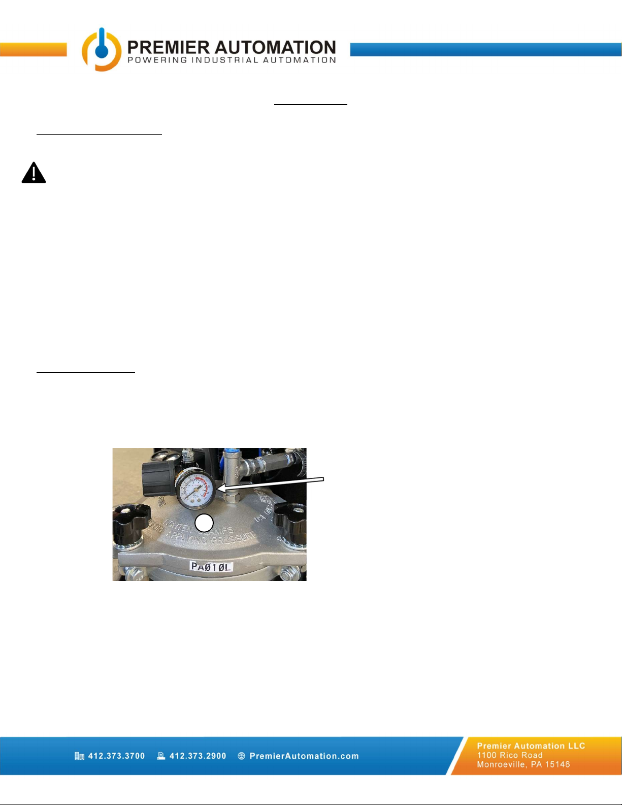
3. Verify the tank pressure gauge reads 0 PSI so the tank is depressurized. Do no proceed to the next step
until depressurization is complete.
FIGURE 4.2.1 Tank Pressure Gauge
4. Unscrew the four clamps on the lid of the tank and pull the clamps away from the tank until they are
upside down and disengaged.
a. Take care not to adjust the air pressure regulator on the tank while adjusting clamps.
Gauge
M
Page 7 of 13
FIGURE 4.2.2 Tank Open
5. Lift and slide the lid towards the back of the unit to gain access to the tank.
6. Carefully pour the solution into the tank. Do NOT exceed the capacity of the tank (max 2.25gal of
liquid). Use a funnel as needed for pouring.
7. Return the lid to the tank and fasten the four clamps evenly and securely. Gradually alternate clamps
during the tightening process to ensure a complete and even seal.
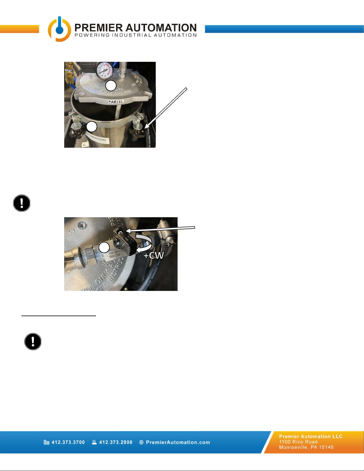
8. MAKE SURE THE TANK DRAIN VALVE IS COMPLETELY CLOSED, ALLOWING THE SOLUTION TO FLOW
TO THE SPRAY GUN.
FIGURE 4.2.3 Tank Drain Valve Closed
9. Replace the front access panel and tighten thumb screws.
4.3 Operating Procedure:
1. Make sure all Before Use Checks and the Filling the Tank Procedures have been completed and the
environment is safe to operate in.
a. VERIFY THE TANK DRAIN VALVE IS COMPLETELY CLOSED (HANDLE IS TO BE PERPENDICULAR
TO THE PIPE), ALLOWING THE SOLUTION TO FLOW TO THE SPRAY GUN.
2. Plug the unit into a 120VAC GFI protected outlet, and the GFI test light will illuminate.
a. Up to 25ft of cord is available.
b. Do not pull if cord is tight.
3. At the HydroCleaner, locate the Power Off/On switch and turn to the On position.
4. The switch will illuminate, an internal fan will start, and the pump will engage to pressurize the
equipment as needed.
5. Once the equipment is pressurized and the pump turns off, the unit is ready to begin spraying.
Tank drain valve in closed position.
Valve is turned clockwise to close.
Clamps are disengaged
and tank is open
M
L
K

Page 8 of 13
a. NOTE: The spray gun will release the contents of the tank into the air; be sure to appropriately
dispense the tank contents following all SDS and safety regulations for the solution dispensing
procedures.
6. Squeeze and hold the trigger on the spray gun to dispense the solution.
a. NOTE: During the spraying process, the pump may turn on/off as needed to maintain required
pressure. This is normal.
7. Release the trigger on the spray gun to stop dispensing the solution.
8. If the desired spray stream is not emitted, the pump, tank, or spray gun may need adjusted
accordingly.
a. See the Spray Adjustments section for detailed instructions.
9. When finished spraying, release the trigger on the spray gun and turn the Power Off/On switch to Off.
10. Follow Care Instructions after every use.
4.4 Spray Adjustment:
1. Make sure all Before Use Checks, Filling the Tank, and Operating Procedures have been completed and
the environment is safe to operate in before adjusting the spray gun.
2. Make sure the HydroCleaner is plugged in and the Power Off/On switch is in the On position.
3. The air cap on the front of the sprayer gun may be rotated to adjust the direction of the spray. Do NOT
exceed 360° and loosen the cap.
4. The liquid flow of the sprayer may be adjusted by rotating the knob clockwise to restrict flow and
counterclockwise to increase flow (see figure below). Adjust as necessary to achieve desired spray.
FIGURE 4.4.1 Spray Gun Liquid and Direction Adjust
5. The pressure of the sprayer may be adjusted by rotating the knob clockwise to increase pressure and
counterclockwise to decrease pressure (see figure below). This is typically operated at full pressure.
Spray Gun Liquid Adjust
Clockwise = Restrict Flow
Counterclockwise = Increase Flow
Spray Gun Air Cap/Direction Adjust
Rotate protruding part to change
direction.
Do NOT exceed 360° and loosen cap.
W
AA

Page 9 of 13
FIGURE 4.4.2 Spray Gun Pattern and Pressure Adjust
6. The spray pattern may be adjusted by rotating the knob clockwise to thin/narrow the spray pattern
and counterclockwise to round the spray pattern.
7. All necessary adjustments should be able to be accomplished on the sprayer gun, but if necessary, the
tank and pump pressures may need adjusted.
8. Typical tank pressure is set between 20-25 PSI, but pressures may vary.
a. To change the tank pressure, loosen thumb screws and remove the front access panel.
b. With the drain valve closed, press and hold the Drain button to pressurize the tank (see Figure
5.1.2).
c. When the tank pressure has stabilized, adjust the regulator. As per the figure below, rotate
clockwise to increase pressure and counterclockwise to decrease pressure to set at desired
pressure setpoint. NEVER EXCEED 45 PSI, as this will over-pressurize the tank.
FIGURE 4.4.3 Tank Pressure Regulator
d. Release Drain button and replace the front access panel and tighten thumb screws.
9. Typically, the pump regulated pressure is set between 50-60 PSI, but pressures may vary.
a. To change the regulated pressure, loosen thumb screws and remove the front access panel.
b. Wait for the tank to depressurize before proceeding.
c. Behind the tank, the pump regulated pressure gauge is visible, along with the regulator.
d. As per the figure below, rotate the pump regulator clockwise to increase pressure and
counterclockwise to decrease pressure to set at desired pressure setpoint. Typically, the
regulated pressure setpoint is at least double the tank pressure. NEVER EXCEED 95 PSI, as this
will over-pressurize the spray gun.
Tank Pressure Regulator
Clockwise = Increase Pressure
Counterclockwise = Decrease Pressure
Spray Gun Pattern Adjust
Clockwise = Narrow Pattern
Counterclockwise = Round Pattern
Spray Gun Pressure Adjust
Clockwise = Increase Pressure
Counterclockwise = Decrease Pressure
V
Y
I
M

Page 10 of 13
FIGURE 4.4.4 Pump Pressure Regulator
10. If the pump regulated pressure was at or below the tank pressure, repeat the process to adjust the
tank pressure to verify it is still at the desired setpoint.
11. Replace front access panel and tighten thumb screws.
5. CARE INSTRUCTIONS
5.1 Emptying the Tank:
NOTE: Chemicals/solution should NEVER be stored inside the tank.
1. Make sure power is off and the unit is unplugged.
2. Loosen thumb screws and remove the front access panel.
3. Place the drain hose into an appropriate collection container, in accordance with SDS instructions, to
capture the contents from the tank. Secure the hose to the container.
4. Open the tank drain valve by turning the handle 90° counterclockwise to be in line with the drainpipe.
FIGURE 5.1.1 Tank Drain Valve Opened
5. Plug the unit into a 120VAC GFI protected outlet. At the HydroCleaner, locate the Power Off/On switch
and turn to the On position.
6. With the drain hose in place, press and hold the Drain button to engage the pump unit to drain the
contents of the tank.
Tank drain valve in open position.
Valve is turned counterclockwise to be
in line with piping.
Pump Regulated Pressure Gauge
Pump Pressure Regulator
Clockwise = Increase Pressure
Counterclockwise = Decrease Pressure
R
T
K

Page 11 of 13
FIGURE 5.1.2 Drain Button
7. When the tank is empty, only air will come out. Release the drain button, then turn the Power Off/On
switch to the Off position.
8. Clean, dry, and carefully store the drain hose inside the HydroCleaner.
9. Replace the front access panel and tighten thumb screws.
5.2 Rinsing the System:
1. Once the tank is empty, it will need to be rinsed thoroughly with WATER.
2. Unscrew the four clamps on the lid of the tank and pull the clamps away from the tank until they are
upside down and disengaged (see Figure 4.2.2).
3. Rinse the interior of the tank lid and hosing and clean/rinse thoroughly (in accordance with SDS
instructions).
4. Follow the Filling and Operating procedures to fill the tank with WATER and flush the system.
5. Operate spray gun with water to flush the liquid hosing (B1) and sprayer head. This should be done for
a minimum of 5 minutes.
6. Follow the Emptying procedure and repeat rinsing process as needed until system is thoroughly rinsed.
7. When the tank is empty, squeeze the spray gun trigger to allow any liquid left in the hoses and spray
gun to drain from the system.
5.3 Storage:
1. Make sure power is off and the unit is unplugged.
2. Follow Care Instructions to rinse and empty the tank before storing.
3. Hold down the spray gun trigger until the system is depressurized.
4. Wipe down/clean the HydroCleaner, spray gun, hose, cord, etc. as necessary (per SDS instructions) to
clean any solution that may have come in contact with the equipment while the spray gun was in use.
5. Unplug the unit from the outlet and return the retractable extension cord into the unit. A soft pull will
engage retraction.
6. Loosely coil the hoses and place on top of the HydroCleaner. Be sure not to crimp hoses and keep from
resting on the floor.
Drain button
Press and hold to actuate.
H

Page 12 of 13
7. Drain the water from the pump unit.
a. Remove the side wall on the HydroCleaner using a 1/8” hex head to access the drain valve on
the pump tank.
b. Open the drain valve on of the pump unit and allow pump to empty (refer to Figure 1.1.5).
FIGURE 5.3.1 Pump Drain Plug
c. Carefully remove the drain pan and safely dispose of the collected water.
d. Close the drain valve.
8. Allow all components to dry completely before storing.
9. Store in a clean, dry location above 40°F.
10. For long term storage, leave the tank lid open.
Pump Drain Plug
U

Page 13 of 13
6. Warranty
Premier Automation, LLC warrants each new Premier product to be free from defects in material and
workmanship. This warranty is applicable only for the normal service life expectancy of the machine or
components to not exceed twelve consecutive months from the date of delivery of the new Premier product to
the original purchaser.
Under no circumstance will it cover any merchandise or components thereof which, in the opinion of the
company, has been subjected to negligent handling, misuse, alteration, an accident, or if repairs have been made
with parts other than those obtainable through Premier Automation, LLC.
Our obligation under this warranty shall be limited to repairing or replacing, free of charge to the original
purchaser, any part that in our judgement shall show evidence of such defect, provided further that such part
shall be returned within thirty (30) days from date of failure to Premier Automation, LLC. through the dealer
and distributor to whom the purchase was made, transportation charges prepaid.
This warranty shall not be interpreted to render us liable for injury or damages of any kind or nature, direct,
consequential, or contingent, to person or property. This warranty does not extend any expense or loss incurred
for labor, supplies, substitute machinery, rental or for any other reason.
There are no warranties, either expressed or implied, of merchantability or fitness for particular purpose
intended for fitness or any other reason.
This warranty is subject to any existing conditions of supply which may directly affect our ability to obtain
materials or manufacture replacement parts.
Premier Automation, LLC. reserves the right to make improvements in design or changes in specifications at
any time, without incurring any obligations to owners of units previously sold.
No one is authorized to alter, modify, or enlarge this warranty nor the exclusions, limitations and reservations.
7. Disclaimer
In no event shall our company be liable for any direct, indirect, punitive, incidental, special consequential
damages, to property or life, whatsoever arising out of or connected with the use or misuse of our
products.
8. Limitation of Liability
In the event of claims of damage or harm to person or property, damage is limited exclusively to
available insurance coverage, if any.
Table of contents


