Edimax GS-5008E User manual

1
GS-5008E
User Manual
11-2021 / V1.0

Contents
I. Product Information.................................................1
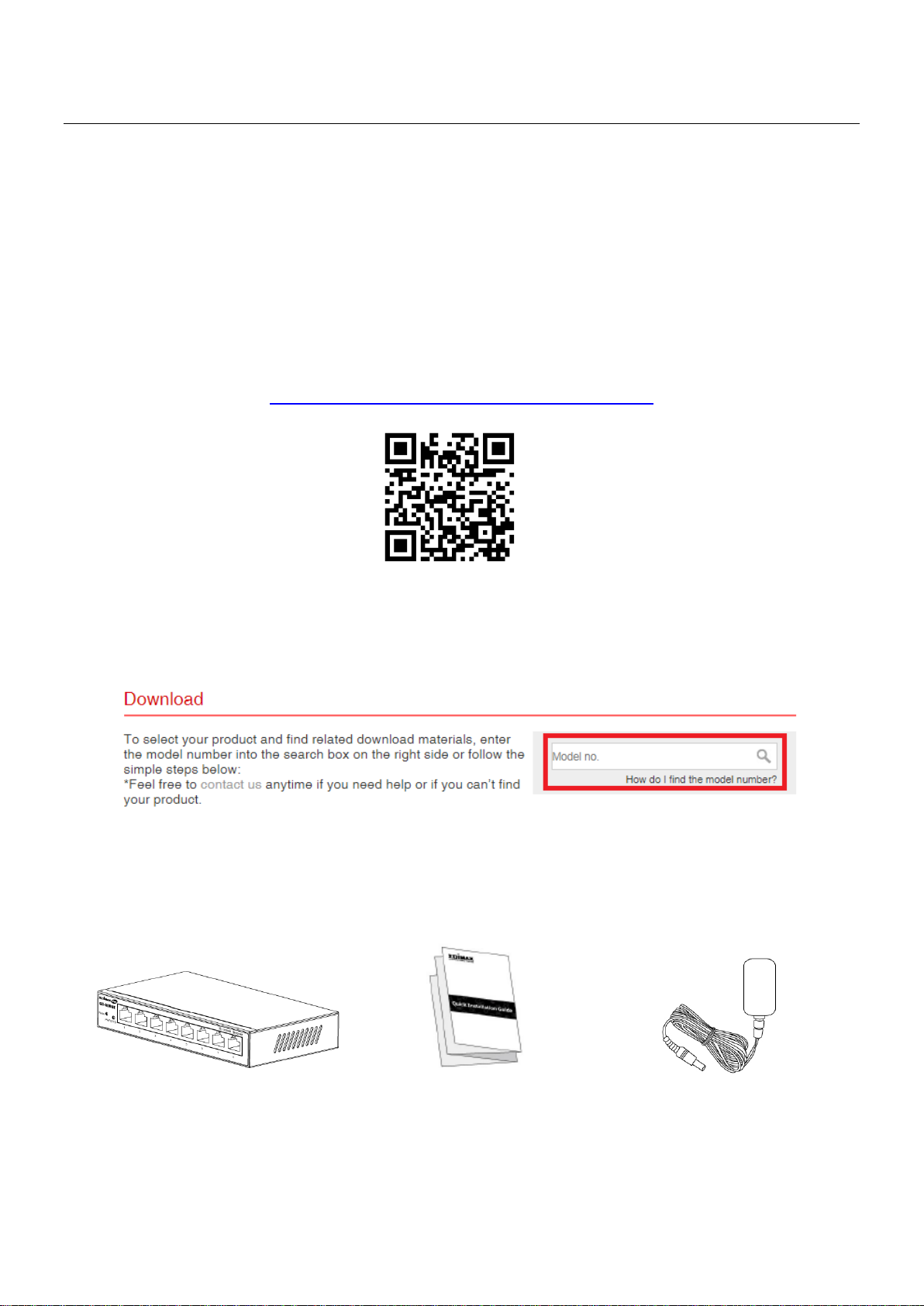
I-1. Package Contents....................................................................... 1
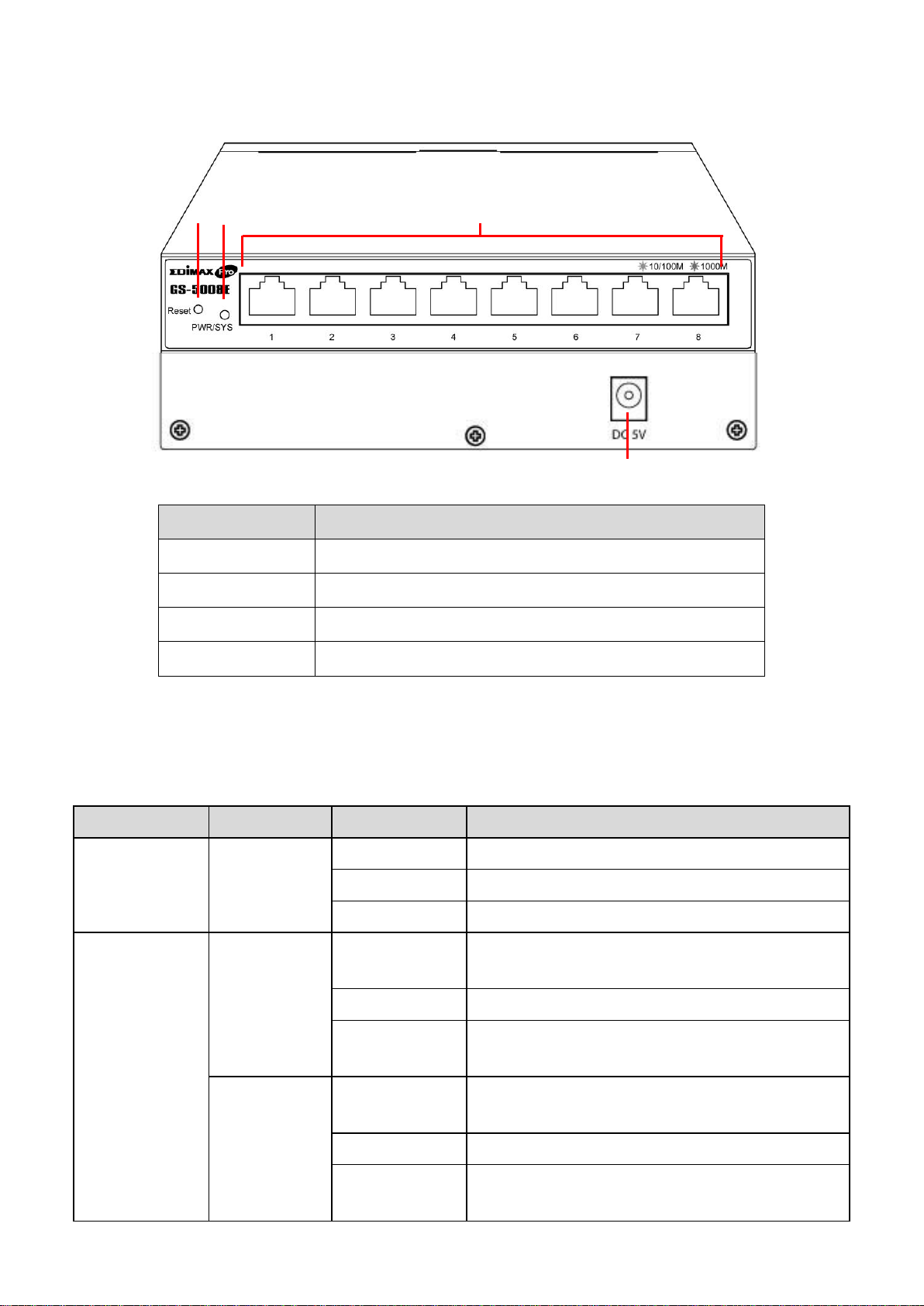
I-2. Hardware Interface .................................................................... 2
I-3. LED Status.................................................................................. 2
II. Installation ..............................................................3
II-1 Connecting to Network............................................................... 3
II-2 Starting the Web-based Configuration Utility ............................. 4
II-3 Launching the Configuration Utility ............................................ 4
III.Web-based Switch Configuration .............................6
III-1 System Information.................................................................... 6
III-2 Management ............................................................................. 7
III-3 Port ........................................................................................... 8
III-4 VLAN.........................................................................................10
III-5 Link Aggregation.......................................................................11
III-6 Port Mirroring...........................................................................12
III-7 QoS...........................................................................................13
III-7-1. Disable QoS.........................................................................13
III-7-2. Port-Based QoS ...................................................................14
III-7-3. IEEE 802.1p QoS...................................................................15
III-8 Broadcast Storm Control ...........................................................16

III-9 Rate Limiting.............................................................................17
III-10 Loop Detect/Prevent .................................................................18
III-11 IGMP Snooping .........................................................................19
III-12 Password ..................................................................................20
III-13 Logout ......................................................................................21

1
I. Product Information
The Edimax Pro GS-5008E web-smart switch equipped with 8 Gigabit Ethernet
ports and rich web managed functions. This switch provides high-speed and
reliable data transfer ideal for network connectivity in the home, small office,
small-and-Medium business and enterprise environments.
You can find all supporting documents from the link below or via QR Code:
https://www.edimax.com/download
(Once you’ve visited the Edimax official website, please enter model no.
“GS-5008E”into the search box to search for your product.)
I-1. Package Contents
GS-5008E
Power Adapter
(5V)
Quick Installation
Guide

2
I-2. Hardware Interface
I-3. LED Status
LED
Color
Status
Description
PWR/SYS
Green
On
The switch is powered on
Flashing
The switch is booting up
Off
Power is disconnected or failed
Port 1-8
(LINK/ACT)
Amber
On
The Port is connected, Link at
10/100M
Flashing
Sending or receiving data
Off
The Port is disconnected or link
failure
Green
On
The Port is connected, Link at
1000M
Flashing
Sending or receiving data
Off
The Port is disconnected or link
failure
No.
Description
1
Reset
2
PWR/SYS
3
LAN Port x 8, LED (LINK/ACT)
4
DC Power Jack
3
4
4
1
2
3

3
II. Installation
Read the following topics and perform the procedures in the correct order.
Incorrect installation may cause damage to the product.
II-1 Connecting to Network
1. There are two ways to physically set up the switch.
˙Place the switch on a flat surface.
˙Wall-mount the switch. The product is designed with wall-mounted
holes. (The wall-mounted mounting screws and accessories are not
included.)
2. Connect the power adapter to the switch and the power outlet.
(Note: Make sure that the "PWR" LED is green.)
3. Plug the standard Cat5e Ethernet cable into the LAN port and connect it to
the computer and prepare for web-based configuration. (Note: Make sure
that the "LAN" LED is green or amber.)
4. Connect any networking device to the switch via Ethernet cable. (Note:
Make sure that the "LAN" LED is green or amber.)
5. Connect the router to the switch via Ethernet cable. (Note: Make sure that
the "LAN" LED is green or amber.) The hardware installation is complete!
1
2
3
4
5
1
Wall-Mount
Power On
Computer
Network Device
Router

4
II-2 Starting the Web-based Configuration Utility
This section describes how to navigate the web-based switch configuration
utility through web browser. Be sure to disable any browser pop-up blocker.
Browser Restrictions
If you are using older versions of Internet Explorer, you cannot directly use
an IPv6 address to access the device. You can, however, use the DNS
(Domain Name System) server to create a domain name that contains the
IPv6 address, and then use that domain name in the address bar in place
of the IPv6 address.
If you have multiple IPv6 interfaces on your management station, use the
IPv6 global address instead of the IPv6 link local address to access the
device from your browser.
II-3 Launching the Configuration Utility
1. Make sure your computer is connected with the switch then open a web
browser.
2. Enter the IP address of the switch you are configuring in the address bar
on the browser (factory default IP address is 192.168.2.1) and then press
Enter. Please make sure that your computer's IP address is in the same
subnet as this switch. The default IP address is an IP address in the range
of 192.168.2.X (X=2-254). You can modify the IP address of your
computer if you need.
Default IP
192.168.2.1
Default User Name
admin
Default Password
1234

5
3. The default username is “admin”and the default password is “1234”.
4. The first time that you log in with the default username and password,
you are required to set a new password.

6
III.Web-based Switch Configuration
The Web Smart switches provide rich functionalities. This chapter describes
how to use the web-based management interface (Web UI) to configure the
switch’s features.
III-1 System Information
This page shows system current information. It also allows user to edit some
system information.
To change the “Device Name”, click on the table title to edit.
Enter the new device name and click the “Apply”button

7
Item
Description
Model Name
Model name of the switch.
Device Name
System name of the switch. The Device name can be
modified.
Firmware
Version
Current running firmware image version.
MAC Address
Base MAC address of the switch.
IPv4 Address
Current system IPv4 address.
Subnet Mask
A 32-bit number that masks an IP address
Gateway
TCP / IP protocol under the gateway
Loop Status
Displays whether or not loops exist in the network
PoE Status
Display PoE status
III-2 Management
Use the Management Access pages to upgrade firmware, restore or backup
the configuration and configure settings of management access.

8
Item
Description
DHCP
Enable: Obtain an IP address from DHCP Server
automatically.
Disable: Use a static IP address
IP Address
Specify the switch static IP address on the static
configuration.
Subnet Mask
Specify the switch subnet mask on the static
configuration.
Gateway
Specify the gateway on the static configuration. The
gateway must be in the same subnet with switch IP
address configuration.
Item
Description
Management
Reboot: You can reboot the switch by pressing the
“Reboot”button.
Reset: You can reset the switch to default by pressing
the “Reset “button.
Item
Description
Configuration
Restore/Backup
Backup: Backup the configurations from this
GS-5008E.
Restore: Restore the configurations choosing
configuration file from PC or NB.
Item
Description
Firmware
Upgrade
Upgrade firmware by selecting the Firmware file
from PC or NB.
III-3 Port
Use the Port pages to configure settings for switch port related features.

9
Item
Description
Port
Port number
Speed
Port speed capabilities.
Auto: Auto speed with all capabilities.
10M Half: Speed with 10Mbps
10M Full: Speed with 20Mbps
100M Half: Speed with 100Mbps
100M Full: Speed with 200Mbps
Connection
Down: Displays port is not in use.
Or link speed if it is in use.
TX(Pkts)
This field shows the number of packets transmitted on
this port.
RX(Pkts)
This field shows the number of packets received on this
port.
Clear
Counters
Click to reset statistics data.

10
III-4 VLAN
This page allows user to configure each port of selected VLANs.
Item
Description
Apply
Click “Apply”to save the values.
Port
Designated port number.
PVID
Enter a Port VLAN ID for each port.
Create New VLAN
Click “Create New VLAN”to enter new
VLAN settings.
VLAN ID
Virtual LAN ID.
Non-Member
Port is not a member of a VLAN.
Tag Egress Member
Tag outgoing packets of a port which is a
member of the VLAN.
Untag Egress Member
Untag outgoing packets of a port which is
a member of the VLAN.
Modify
Modify port settings of a specific VLAN.
Delete
Delete a specific VLAN.
NOTE: The PVID of a port is the VLAN id that will be assigned to any
untagged frames entering the switch on that port (assuming the switch is
using port-based VLAN classification). Each port can set a PVID ONLY.

11
III-5 Link Aggregation
Link aggregation is the grouping of physical ports into one logical
higher-capacity link. You may want to trunk ports if, for example, it is cheaper
to use multiple lower-speed links than to under-utilize a high-speed, but more
costly, single-port link.
The Switch supports the link aggregation IEEE802.3ad standard. This standard
describes the Link Aggregation Control Protocol (LACP), which is a protocol
that dynamically creates and manages trunk groups.
When you enable LACP link aggregation on a port, the port can automatically
negotiate with the ports at the remote end of a link to establish trunk groups.
LACP also allows port redundancy, that is, if an operational port fails, then one
of the “standby” ports become operational without user intervention.
Please note that:
LACP only works on full-duplex links.
All ports in the same trunk group must have the same media type, speed,
duplex mode and flow control settings.
Configure trunk groups or LACP before you connect the Ethernet switch
to avoid causing network topology loops.

12
Item
Description
LACP Global
State
Select “Enable “or “Disable”to enable or disable
Link Aggregation Control Protocol.
Link Aggregation
Algorithm
Select the outgoing traffic distribution type.
Packets from the same source and/or to the same
destination are sent over the same link within the
trunk.
By default, the Switch uses the MAC SA & DA
distribution type.
MAC SA & DA: To distribute traffic based on a
combination of the packet’s source MAC address
and destination MAC address.
MAC SA: To distribute traffic based on the packet’s
source MAC address.
MAC DA: To distribute traffic based on the
packet’s destination MAC address.
Link Group
Activity
Switch TX LACP control packet Passive or Active.
By default, the Switch uses the Passive mode.
Link Group
Member
The check box of ports would be checked after the
port is added into the Link Group successfully.
Apply
Click Apply to save your changes.
III-6 Port Mirroring
Port mirroring selects the network traffic for analysis by a network analyzer.
This is done for specific ports of the switch. You may configure the ports as
source ports or configure one of the ports is as a destination port.

13
Item
Description
Enable Mirror
Enable/disable port mirroring.
Mirror Direction
Select the mirror direction:
Both( Ingress and Egress)
Ingress
Egress
Monitor Port
Select the mirror destination port.
Mirrored Port List
Choose the destination of the mirrored port.
Apply
Click Apply to save the changes.
III-7 QoS
There are two options of QoS mechanism are provided for traffic forwarding:
port-based QoS and 802.1p QoS. Users can switch to either of them on the
Web page.
When Quality of Service (QoS) feature is enabled, traffic will be forwarded
according to the predefined setting of port-based QoS or 802.1p QoS.
If QoS type is set as port-based, the priority is based on the incoming port of
the traffic.
The current queue for each port is configured as below.
III-7-1. Disable QoS

14
III-7-2. Port-Based QoS
Queue0
Low Priority
Queue1
Normal Priority
Queue2
Medium Priority
Queue3
High Priority
Item
Description
Schedule Method
WFQ(Weighted Fair Queue)
Strict Priority
Weight
(WFQ Method
ONLY)
WFQ weight options:
Apply
Click Apply to save the changes.

15
III-7-3. IEEE 802.1p QoS
If QoS type is set to 802.1p, the priority is based on the incoming PCP field of
the traffic. The current queue for each PCP is configured as below.
PCP value
Priority
Acronym
Traffic types
1
0 (lowest)
BK
Background
0
1 (default)
BE
Best effort
2
2
EE
Excellent effort
3
3
CA
Critical applications
4
4
VI
Video, < 100ms
latency and jitter
5
5
VO
Voice, < 10 ms latency
and jitter
6
6
IC
Internetwork control
7
7 (highest)
NC
Network control

16
Item
Description
Schedule Method
WFQ(Weighted Fair Queue)
Strict Priority
Weight
(WFQ Method
ONLY)
WFQ weight options:
Apply
Click Apply to save the changes.
III-8 Broadcast Storm Control
A traffic storm occurs when packets flood the network ports, creating traffic
and impacting network performance in a negative way. The broadcast storm
control feature prevents network ports from being disrupted by a broadcast,
multicast, or DLF (Destination Lookup Failure) traffic storm.

17
Select a limit in the drop down menus behind the storm control features and
click “Apply”to apply the settings.
III-9 Rate Limiting
When the Rate Control feature is enabled, GS-5008E provides Ingress/Egress
traffic Rate Control per port for broadcast traffic type. Enable this feature to
reduce broadcast packets in your network.
Click the drop down menus to change the Ingress/Egress rate, and click “Apply”
to apply the setting.
Table of contents
Other Edimax Switch manuals

Edimax
Edimax EK-08RE User manual

Edimax
Edimax ES-5500P User manual

Edimax
Edimax EK-PAK2 User manual

Edimax
Edimax EK-16RE Instruction sheet

Edimax
Edimax ES-1016 User manual

Edimax
Edimax EK-UAK4 User manual

Edimax
Edimax ES-5224RS+ User manual

Edimax
Edimax ES-3116RL User manual

Edimax
Edimax ES-516G+ User manual

Edimax
Edimax EU-4230 User manual

Edimax
Edimax SP-1101W User manual

Edimax
Edimax EU-HB4M User manual

Edimax
Edimax ES-3116RE+ User manual

Edimax
Edimax EK-PS2C Reference guide

Edimax
Edimax EU-HB4S User manual

Edimax
Edimax ES-5816P Reference guide

Edimax
Edimax ER-5390P User manual

Edimax
Edimax 24 10 User manual

Edimax
Edimax ES-3305P User manual

Edimax
Edimax EU-PC2C User manual