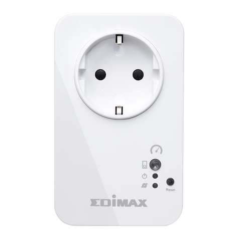
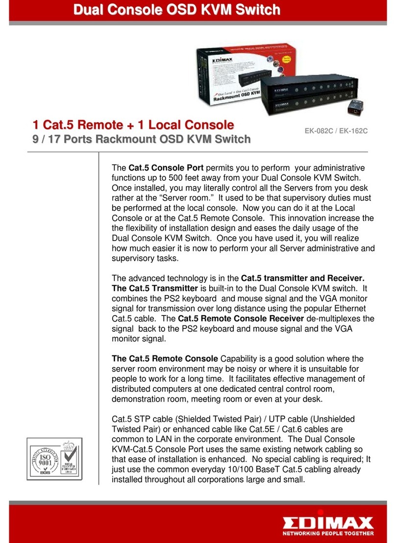
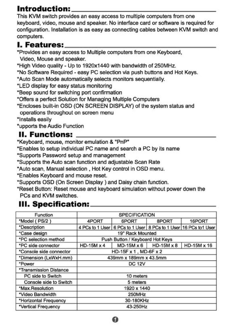
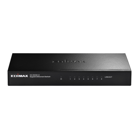
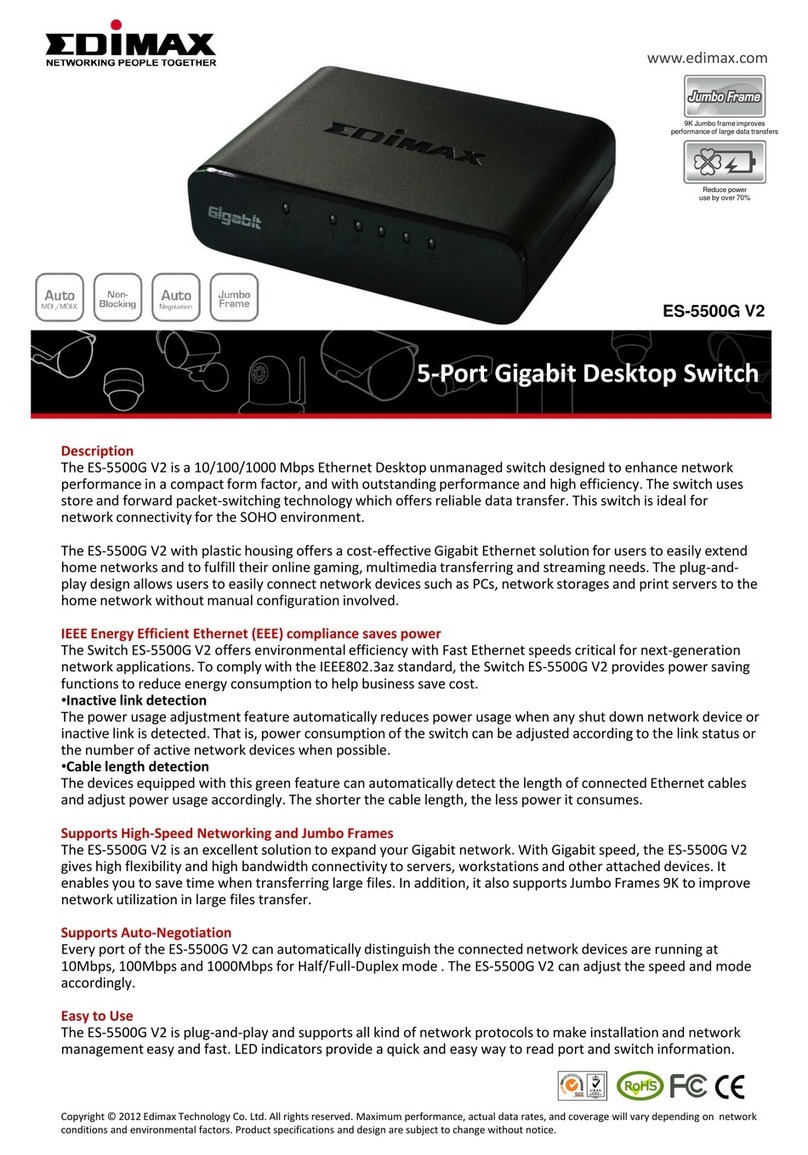
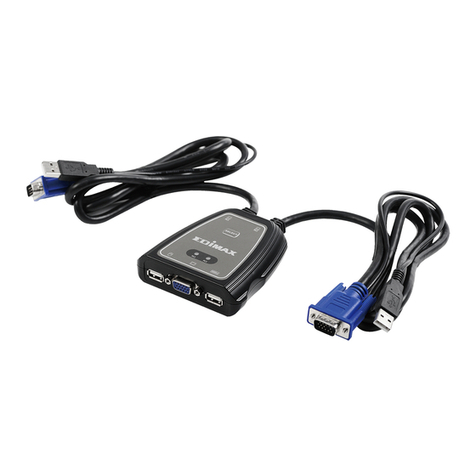
Edimax PS-3101P User manual

0
5
5
/
/
8
8
/
/1
16
6
P
Po
or
rt
ts
s
S
SO
OH
HO
O
F
Fa
as
st
t
E
Et
th
he
er
rn
ne
et
t
S
Sw
wi
it
tc
ch
he
es
s
Q
Qu
ui
ic
ck
k
I
In
ns
st
ta
al
ll
la
at
ti
io
on
n
G
Gu
ui
id
de
e

1
Content Table
English ..............…………...............……………... 2
Český ................................................................... 5
Deutsch ............................................................... 8
Español .............................................................. 11
Français ............................................................. 14
Italiano ............................................................... 17
Magyar ............................................................... 20
Nederlands......................................................... 23
Polski ................................................................. 26
Português .......................................................... 29
Русский.............................................................. 32
Türkçe ................................................................ 35

2
English.
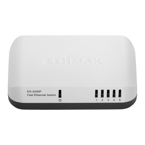
Front Panel & Connectors
Fast Ethernet Switch LED Panel
LED Color Status Description
Lit Power is supplied
PWR
(Power) Green Off No power
Lit A valid link is established
Flash Data packets received
LNK/ACT
(Link/Activity) Green
Off No link is established
Lit This port run at 100Mbps
SPEED
(10/100M) Yellow Off This port run at 10Mbps

3
1. Operating Environment
This switching hub must be installed and operated within the
limits of specified operating temperature (32-131°F) and
humidity (10~95% Non-condensing).
zDo not place objects on top of the unit.
zDo not obstruct any vents at the sides of the unit.
zDo not position the unit near any heating source such
as heater, radiator, or direct exposure to sun.
Prevent entering of water and moisture into the unit. If
necessary, use dehumidifier to reduce humidity.
2. Connecting to network devices
The RJ-45 ports on the switch support Auto-MDI/MDI-X
function which allows using straight-through or cross-over
type cables to connect this switch to workstation or hub.
Connect one end of the network cable to the RJ-45 port on
the rear panel, and connect the other end of the network
cable to the RJ-45 port on the network device. Follow the
same procedure to connect all the RJ-45 ports of the switch.
The UTP network cables must comply with EIA/TIA 568
specifications and Category 5 standard for 100Mbps data
transmission. Maximum length: using UTP cable, between
the switch and connected device is 100 meters (300ft).
Once the network cable is connected to both ends and the
attached network device is powered on, the green LNK/ACT
LED should be lit.
3. Connecting the power
Connect the power adapter to the power connector on the
rear panel of the unit; the green Power LED on the front
panel should be lit.

4
Trouble Shooting
1. Power LED is not lit
zCheck if the power cord is properly connected to the
external power adapter and the power outlet. Make sure
the DC power jack is firmly plugged into the power socket
of the switch.
2. Link/Activity is not lit when connect to 100Mbps device
zCheck the power switch of the network device attached to
the switch; make sure it is turned ON.
zCheck the network cable; make sure it is properly
connected to the switch and the network device.
zCheck the network cable; make sure the UTP cables
comply with EIA/TIA 568 and Category 5 specification.
[!] Contact your dealer if problem persist.

5
Český.
Čelní panel a konektory
Panel s diodami LED switche pro Fast Ethernet
Dioda LED Barva Stav Popis
Svítí Zařízení je napájeno
PWR
(Napájení) Zelená Nesvítí Zařízení není napájeno
Svítí Je vytvořeno platné
připojení
Bliká Jsou přijímány datové
pakety
LNK/ACT
(Připojení/Aktivita) Zelená
Nesvítí Není vytvořeno platné
připojení
Svítí Tento port pracuje s
rychlostí 100 Mb/s
SPEED
(10/100 M) Žlutá
Nesvítí Tento port pracuje s
rychlostí 10 Mb/s

6
1. Provozní prostředí
Tento switch/hub musí být nainstalován a provozován v
prostředí, které splňuje limity, specifikované provozní teploty
(32-131°F) a vlhkosti (10-95% bez kondenzace).
zNa horní plochu zařízení nepokládejte žádné předměty.
zNezakrývejte žádné výřezy po stranách zařízení.
zNeumisťujte toto zařízení do blízkosti jakýchkoliv
topných těles, jako je například topení, radiátor ani jej
nevystavujte přímému slunečnímu záření.
Zabraňte vniknutí vody a vlhkosti do zařízení. V případě
potřeby použijte pro snížení vlhkosti odstraňovačvlhkosti.
2. Připojení k síťovým zařízením
Porty RJ-45 na switchi podporují funkci Auto-MDI/MDI-X,
která umožňuje pro propojení tohoto switche s pracovní
stanicí nebo rozbočovačem (hubem) použít přímé nebo
křížené kabely.
Zapojte jeden konec síťového kabelu do portu RJ-45 na
zadním panelu zařízení a druhý konec síťového kabelu
zapojte do portu RJ-45 na síťovém zařízení. Stejným
způsobem zapojte všechny porty RJ-45 switche.
Síťové kabely UTP musejí odpovídat specifikacím EIA/TIA
568 a norměpro Kategorii 5 pro datové přenosy rychlostí
100 Mb/s. Maximální délka: při použití kabelu UTP mezi
switchem a zapojeným zařízením je 100 metrů.
Po zapojení obou koncůsíťového kabelu a po zapnutí
síťového zařízení by se měla rozsvítit zelená dioda LED
LNK/ACT.
3. Zapojení zdroje napájení
Zapojte síťový adaptér ke konektoru pro napájení na zadním
panelu zařízení; Měla by se rozsvítit zelená dioda LED
napájení (Power) na čelním panelu.

7
Odstraňování potíží
1. Dioda LED napájení (Power) nesvítí
zZkontrolujte, zda je k externímu síťovému adaptéru a do
síťové zásuvky správnězapojen síťový napájecí kabel.
Prověřte, zda je konektor stejnosměrného napájení
zapojen do odpovídající zdířky na switchi.
2. Indikátor Link/Activity při připojení zařízení s rychlostí
100 Mb/s nesvítí
zZkontrolujte, zda je síťové zařízení, připojené ke switchi,
zapnuté; ujistěte se, že je zapnuté (ON).
zZkontrolujte síťový kabel; ujistěte se, že je správnězapojen
ke switchi a k síťovému zařízení.
zZkontrolujte síťový kabel; ujistěte se, že kabely UTP
odpovídají specifikacím EIA/TIA 568 a Kategorii 5.
[!] Pokud problém přetrvává, obraťte se na svého
prodejce.

8
Deutsch.
Vorderseite & Anschlüsse
Fast Ethernet Switch LED-Anzeige
LED Farbe Status Beschreibung
Leuchtet Es liegt Strom an
PWR
(Strom) Grün Aus Kein Strom
Leuchtet Eine gültige Verbindung
wurde hergestellt
Blinken Datenpakete werden
empfangen
LNK/ACT
(Vervindung/Aktivität) Grün
Aus Keine Verbindung
hergestellt
Leuchtet
Dieser Port hat eine
Datenübertragungsrate
von 100 Mbps
SPEED
(10/100M) Gelb
Aus
Dieser Port hat eine
Datenübertragungsrate
von 10 Mbps

9
1. Betriebsumgebung
Bei der Installation und beim Betrieb dieses Switching-Hubs
müssen die vorgeschriebenen Grenzen für
Betriebstemperatur (0-55 °C) und Luftfeuchte (10~95 %
keine Kondensation) eingehalten werden.
zStellen Sie keine Gegenstände auf das Gerät.
zBlockieren Sie die Entlüftungsöffnungen an den Seiten
des Geräts nicht.
zStellen Sie das Gerät nicht in der Nähe von
Wärmequellen wie z. B. Heizkörpern und Heizstrahlern
auf und vermeiden Sie direkte Sonneneinstrahlung.
Sorgen Sie dafür, dass kein Wasser oder Feuchtigkeit in das
Gerät eindringen kann. Wenn notwendig, sollten Sie zur
Reduzierung der Luftfeuchtigkeit einen Entfeuchter
einsetzen.
2. Anschluss an Netzwerkgeräte
Die RJ45-Ports des Switches unterstützen die
Auto-MDI/MDI-X-Funktion. Deshalb ist es möglich, diesen
Switch mit Straight-Through- oder Crossover-Kabeln an
einen Arbeitsplatzrechner oder Hub anzuschließen.
Verbinden Sie ein Ende des Netzwerkkabels mit einem
RJ45-Port auf der Rückseite, und verbinden Sie das andere
Ende des Netzwerkkabels mit dem RJ45-Port des
Netzwerkgeräts. Die Vorgehensweise beim Anschließen ist
bei allen RJ45-Ports des Switches gleich.
Die UTP-Netzwerkkabel müssen den Spezifikationen für
EIA/TIA 568 und dem Kategorie 5-Standard für
Datenübertragungen mit 100 Mbps entsprechen. Maximale
Länge: Bei einem UTP-Kabel beträgt die max. Länge
zwischen dem Switch und dem angeschlossenen Gerät 100
Meter.
Wenn das Netzwerkkabel an beiden Enden verbunden und

10
das angeschlossene Netzwerkgerät angeschaltet ist, sollte
die grüne LNK/ACT-LED leuchten.
3. Anschluss der Stromversorgung
Schließen Sie das Netzgerät an den Netzanschluss auf der
Rückseite des Geräts an; die grüne Betriebs-LED auf der
Vorderseite sollte aufleuchten.
Fehlersuche
1. Die Betriebs-LED leuchtet nicht
zÜberprüfen Sie, ob das Netzkabel richtig mit dem externen
Netzgerät und der Steckdose verbunden ist. Stellen Sie
sicher, dass der DC-Netzstecker fest in die Steckdose des
Switches gesteckt ist.
2. Link/Activity leuchtet nicht, wenn ein Gerät mit 100 Mbps
angeschlossen ist
zÜberprüfen Sie den Netzschalter des Netzwerkgeräts,
welches an den Switch angeschlossen ist; stellen Sie
sicher, dass dieser AN ist.
zÜberprüfen Sie das Netzwerkkabel; stellen Sie sicher, dass
es richtig an den Switch und das Netzwerkgerät
angeschlossen ist.
zÜberprüfen Sie das Netzwerkkabel; stellen Sie sicher, dass
das UTP-Kabel den Spezifikationen für EIA/TIA 568 und
der Kategorie 5 entspricht.
[!] Wenden Sie sich an Ihren Händler, wenn Sie
das Problem nicht lösen können.

11
Español.
Panel frontal y Conectores
Panel LED del interruptor Ethernet rápido
LED Color Estado Descripción
Encendida Conectado a la red
PWR
(Energía) Verde Apagado Sin energía
Encendida
Se ha establecido
correctamente una
conexión
Llama Paquetes de datos
recibidos
LNK/ACT
(Conexión/Actividad) Verde
Apagado No se ha establecido
ningún enlace
Encendida Este puerto funciona
a 100Mbps
VELOCIDAD
(10/100M) Amarillo
Apagado Este puerto funciona
a 10Mbps

12
1. Entorno de funcionamiento
El núcleo del interruptor debe instalarse y ponerse en
funcionamiento conforme a los límites establecidos para la
temperatura de funcionamiento (32-131°F) y la humedad
(10~95% Sin condensación).
zNo coloque los objetos en la parte superior de la
unidad.
zNo obstruya ninguna salida de ventilación situada a los
lados de la unidad.
zNo coloque la unidad cerca de ninguna fuente de calor
como los calentadores, radiadores, ni la exponga
directamente al sol.
Impida cualquier entrada de agua y humedad en la unidad.
Si es necesario, utilice el deshumidificador para reducir la
humedad.
2. Conexión a los dispositivos de la red
Los puertos RJ-45 del interruptor tienen una función
Auto-MDI/MDI-X que permite utilizar cables rectos o
cruzados para conectar el interruptor a la estación de trabajo
o al núcleo.
Conecte un cabo del cable de la red al puerto RJ-45 del
panel trasero, y conecte el otro cabo del cable de red en el
puerto RJ-45 del dispositivo de red. Realice el mismo
procedimiento para conectar todos los puertos RJ-45 del
interruptor.
Los cables de red UTP deben ser conformes a las
especificaciones de la normativa EIA/TIA 568 y a las normas
establecidas para la categoría 5 para la transmisión de datos
a una velocidad de 100Mbps. Largo máximo: utilizando el
cable UTP, la distancia entre el interruptor y el dispositivo
conectado no podrá superar los 100 metros (300ft).
Cuando haya conectado el cable de red a ambos lados y

13
haya encendido el dispositivo de red conectado, deberá
encenderse la indicación verde LNK/ACT LED.
3. Conexión a la red
Conecte el adaptador de corriente al conector de corriente
en la parte trasera de la unidad; Se encenderá en verde la
indicación LED del panel frontal.
Problemas de funcionamiento
1. EL indicador de corriente LED no está encendido
zCompruebe si el cable de corriente se ha conectado
correctamente al adaptador externo de corriente y al
enchufe. Asegúrese de que la toma de CC se ha
introducido correctamente en el enchufe del interrumptor.
2. El indicador Conexión/Atividad no se enciende cuando
lo conecto al dispositivo de 100Mbps
zCompruebe que el interrumpor del dispositivo de red se
encuentra conectado al interruptor; Asegúrese de que está
encendido.
zCompruebe el estado del cable de red; Asegúrese de que
se encuentra debidamente conectado al interruptor y al
dispositivo de red.
zCompruebe el estado del cable de red; Asegúrese que los
cables UTP son compatibles con la normativa EIA/TIA 568
y las indicaciones de la categoría 5.
[!] Póngase en contacto con su distribuidor si no
logra solucionar el problema.

14
Français.
Face avant & Prises
Panneau de voyants du switch
Voyant Couleur Etat Description
Allumé L'alimentation est active
PWR
(Alimentation) Vert Eteint Alimentation coupée
Allumé Une connexion valide
est établie
Clignote Lots de données reçus
LNK/ACT
(Connexion/Activité) Vert
Eteint Aucune connexion
établie
Allumé Ce port fonctionne à
100Mo/sec
DEBIT
(10/100Mo) Jaune
Eteint Ce port fonctionne à
10Mo/sec

15
1. Environnement d'utilisation
Le hub doit être installé et utilisé dans les limites spécifiées
de températures (32-131°F/0 à 55°C) et d'humidité (10~95%
sans condensation).
zNe posez rien sur le dessus de l'appareil.
zN'obturez aucun orifice sur les côtés de l'appareil.
zNe placez l'appareil près d'aucune source de chaleur
telle qu'un radiateur ou les rayons directs du soleil.
Evitez tout contact avec de l'eau ou toute autre source
humide. Si nécessaire, utilisez un déshumidificateur pour
réduire l'humidité.
2. Raccordement aux éléments du réseau
Les ports RJ-45 sont compatibles avec les fonctions
Auto-MDI/MDI-X ce qui vous permet d'utiliser des câbles
droits ou croisés pour reliés ces prises au poste de travail ou
au hub.
Raccordez une extrémité du câble réseau au port RJ45 du
panneau arrière et raccordez l'autre extrémité du câble
réseau au port RJ45 de l'appareil en réseau. Suivez la même
procédure pour raccorder tous les ports RJ45 du switch.
Les câbles réseau UTP doivent être conformes aux
prescriptions EIA/TIA 568 et à la norme de catégorie 5
concernant les transmissions de données à 100 Mo/sec.
Longueur maximum : Si vous utilisez un câble UTP, la
longueur maximum entre le switch et l'appareil connecté doit
être de 100 mètres (300pieds).
Une fois le câble réseau raccordé des deux cotés et
l'appareil allumé, le voyant vert LNK/ACT doit s'allumer.

16
Raccordement de l'alimentation électrique
Raccordez l'adaptateur électrique à la prise d'alimentation à
l'arrière de l'appareil ; Le voyant vert l'alimentation sur la face
avant doit s'allumer.
Dépannage
1. Le voyant d'alimentation ne s'allume pas
zVérifiez que le câble d'alimentation est correctement
branché sur l'adaptateur électrique externe et dans la prise
de courant. Assurez-vous que la prise jack est fermement
branchée dans la prise d'alimentation du switch.
2. Le voyant LNK/ACT (Connexion/Activité) ne s'allume pas
lors d'une connexion à un appareil 100Mo/sec
zVérifiez l'interrupteur de l'appareil raccordé au switch;
Assurez-vous qu'il soit allumé.
zVérifiez la câble réseau ; Assurez-vous qu'il est
correctement raccordé au switch et à l'appareil en réseau.
zVérifiez la câble réseau ; Assurez-vous que les câbles UTP
sont conformes avec les prescriptions EIA/TIA568 et avec
celles de la catégorie 5.
[!] Contactez votre revendeur si le problème
persiste.

17
Italiano.
Pannello Frontale & Connettori
Pannello LED Interruttore Fast Ethernet
LED Colore Stato Descrizione
Acceso L'alimentazione è
fornita
PWR
(Accensione) Verde
Spento Nessuna
alimentazione
Acceso
Viene stabilito un
collegamento
valido
Lampeggia Pacchetti di dati
ricevuti
LNK/ACT
(Collegamento/Attività) Verde
Spento
Nessun
collegamento
viene stabilito
Acceso Questa porta opera
a 100Mbps
VELOCITA'
(10/100M) Giallo
Spento Questa porta opera
a 10Mbps

18
1. Ambiente di Funzionamento
Questo centro di commutazione deve essere installato e
adoperato entro i limiti della temperatura di funzionamento
specificata (32-131°F) e umidità (10~95% Senza condensa).
zNon posizionare oggetti sull'unità.
zNon ostruire nessun foro di ventilazione ai lati dell'unità.
zNon posizionare l'unità vicino o nei pressi di alcuna
fonte di calore, come stufe, termosifoni o esposizione
diretta al sole.
Impedire l'entrata dell'acqua e umidità nell'unità. Se
necessario, usare un deumidificatore per ridurre l'umidità.
2. Collegamento ai dispositivi di rete
Le porte RJ-45 sull'interruttore supportano la funzione
Auto-MDI/MDI-X che permette di utilizzare tipi di cavi dritti o
incrociati per collegare questo interruttore alla stazione di
lavoro o centro.
Collegare un'estremità del cavo di rete alla porta RJ-45 sul
pannello posteriore, e collegare l'altra estremità del cavo di
rete alla porta RJ-45 sul dispositivo di rete. Seguire la stessa
procedura per collegare tutte le porte RJ-45 dell'interruttore.
I cavi di rete UTP devono essere conformi alle specifiche
EIA/TIA 568 e alla Categoria 5 standard per la trasmissione
dei dati 100Mbps. Lunghezza massima: usando il cavo UTP,
tra l'interruttore e il dispositivo connesso è 100 metri (300ft).
Una volta che il cavo di rete è collegato a entrambe le
estremità e il dispositivo di rete fissato è acceso, il LED
LNK/ACT verde dovrebbe essere illuminato.
3. Collegamento dell'accensione
Collegare l'adattatore di accensione al connettore di
alimentazione sul pannello posteriore dell'unità; Il LED di
Accensione verde sul pannello frontale dovrebbe essere

19
illuminato.
Risoluzione dei problemi
1. Il LED di accensione non è illuminato
zVerificare che il cavo di alimentazione sia collegato
correttamente all'adattatore di alimentazione esterno e alla
presa di alimentazione. Assicurarsi che la presa di
alimentazione CD sia inserita saldamente nella presa di
alimentazione dell'interruttore.
2. Il Collegamento/Attività non viene illuminato quando
viene collegato al dispositivo 100Mbps
zVerificare l'interruttore di alimentazione del dispositivo di
rete fissato all'interruttore; assicurarsi che sia acceso.
zVerificare il cavo di rete; assicurarsi che sia collegato
correttamente all'interruttore e al dispositivo di rete.
zVerificare il cavo di rete; assicurarsi che i cavi UTP siano
conformi a EIA/TIA 568 e alla specifica di Categoria 5.
[!] Contattare il rivenditore se il problema persiste.
This manual suits for next models
1
Table of contents
Languages:
Other Edimax Switch manuals

Edimax
Edimax GS-3008P User manual

Edimax
Edimax EK-2U2CA User manual

Edimax
Edimax EU-HB4S User manual

Edimax
Edimax GS-3005P User manual

Edimax
Edimax EU-4306 User manual

Edimax
Edimax GS-5424PLG Setup guide

Edimax
Edimax ES-5160G+ V2 User manual

Edimax
Edimax HP-5101ES User manual

Edimax
Edimax ES-3305P User manual

Edimax
Edimax GS-1016 User manual

Edimax
Edimax ES-5224RS+ User manual

Edimax
Edimax GS-1005E User manual

Edimax
Edimax ES-3308P User manual

Edimax
Edimax EU-PC2C User manual

Edimax
Edimax ER-5390P User manual

Edimax
Edimax ES-3208P User manual

Edimax
Edimax ES-3316P User manual

Edimax
Edimax EU-HB4P User manual

Edimax
Edimax Hub User manual

Edimax
Edimax ES-5500P User manual