EDISecure DCP360i User guide

KAT- T189-007
Startup Guide
Direct Dye Sublimation Printer
DCP360i
Model
See pages 5 to 8
Notes for Safe Operation
Before Use
See pages 10 to 17
Setting Up the Printer
See pages 18 to 19
See page 20
See pages 12 to 13
See pages 14 to 16
See pages 21 to 24
See pages 25 to 28
Read Me First Changing of Ink Ribbon
Setup
Conne ting to the Host Computer
Installation of DCP360i software
Setting / Replacement of Card
Installation of Software
Maintenance
How to Read the Instruction Manual
(Electronic Manual)
Troubleshooting
Setup and Basic Usage of the Printer
Che king Conne tion with the Host Computer
Thank for pur hasing this produ t.
Please read this manual arefully before use to ensure orre t operation.
It is parti ularly important to read the Notes for safe operation. After reading, retain this
manual arefully for future referen e.
The produ t number is important for quality ontrol. Upon pur hase, he k the ba k of
the unit to make sure that the produ t number is orre tly displayed.
Notes about this manual
(1)This manual may not be reprinted in any way without permission.
(2)The ontents of this manual, as well as the spe ifi ations and design of this produ t,
may hange without noti e.
(3)The illustrations used in this manual may differ slightly from the a tual produ t.

2
Declaration of Conformity
Model Number: DCP360iyyyyy(y=A-Z,0-9 or blank)
Produ t name: Card Printer
We herewith de lare that the above mentioned produ t omplies with the following oun il
dire tives and harmonized standards.
Coun il Dire tives: 1999/5/EC relating to radio equipment and tele ommuni ations terminal
equipment.
89/336/EEC relating to ele tromagneti ompatibility.
73/23/EEC relating to ele tri al equipment designed for use within
ertain voltage limits.
Harmonized Standards: EN55022:1998+A1:2000 +A2:2003 Class B
EN55024:1998+A1:2001+A2:2003
EN61000-3-2:2000
EN61000-3-3:1995+A1:2001
EN60950-1:2001
EN50371:2002
EN300 330-2:V1.1.1
EN301 489-03:V1.4.1
Manufa ture:
Victor Company of Japan, Limited
2969-2, Ishikawa-cho, Hachioji-shi, Tokyo, 92-8620, Japan
Importer and distributer:
Digital Identifications Solutions Group of Companies.
Teckstraße 52, D-73734 Esslingen, Germany
Tel : (7 )34 689 -0 , Fax: (7 ) 34 689-550
Year to begin affixing CE Marking: 2005
Ha hioji-shi, June , 2006
Pla e, Date Toru Shimizu General Manager-Quality Control
Vi tor Company of Japan, Limited

3
For USA only
For Canada only
Machine Noise
Sound power level: less than 70 dB (A) according to DIN45635 part 9 (EN27779).
The measurements are to be made according to DIN 45635 part 20 9 or EN27779, respectively.
Operation is subject to the following two conditions:
( ) this device may not cause interference, and (2) this device must accept any interference, including
interference that may cause undesired operation of the device.
For EU only
NOTE: Changes or modifications not expressly approved by the party responsible for compliance could void
the user’s authority to operate the equipment.
NOTE: This equipment has been tested and found to comply with the limits for a Class B digital device, pursu-
ant to part 5 the FCC Rules. These limits are designed to provide reasonable protection against
harmful interference in a residential installation. This equipment generates, uses and can radiate radio
frequency energy and, if not installed and used in accordance with the instructions, may cause harmful
interference to radio communications. However, there is no guarantee that interference will not occur in
a particular installation. If this equipment does cause harmful interference to radio or television recep-
tion, which can be determined by turning the equipment off and on, the user is encouraged to try to
correct the interference by one or more of the following measures:
– Reorient or relocate the receiving antenna.
– Increase the separation between the equipment and receiver.
– Connect the equipment into an outlet on a circuit different from that to which the receiver is con-
nected.
– Consult the dealer or an experienced radio/TV technician for help.

4
Contents
Notes for safe operation................................ 5
Before use..................................................... 7
Printer Characteristics ...........................................7
Checking Accessories ...........................................7
Content of Attached CD-ROM ...............................7
Protection of Color Printing Part ............................ 7
Handling the Ink Ribbon and Card ........................7
Cautions for Handling ........................................ 7
Storage Method ................................................. 7
Storage and Handling of Card After Printing......8
Purchase of Ink Ribbon and Card...................... 8
Escape Clause ......................................................8
Part Names .................................................. 9
(Front / Right)..................................................... 9
(Rear / Left)........................................................ 9
(When Printer Door is Open) ............................. 9
Setup........................................................... 0
Location for Installation....................................... 0
Setting Up the Printer ......................................... 0
Connecting the Laminator................................ 0
Connecting the Power Cord.............................
Mounting the Card Stacker ..............................
Ejection of Card ...............................................
Setting the Ink Ribbon...................................... 2
Adjusting Card Thickness ................................ 4
Setting the Card ............................................... 4
When Using a Magnetic Card .......................... 6
When Using a Contact-type IC Card................ 6
Supply of Card ................................................. 6
Connecting the USB Cable.................................. 7
Connecting Multiple Printers................................ 7
Installation of Software................................ 8
Connecting to the Host Computer ....................... 8
Software Licensing Agreement ........................ 8
About software ................................................. 8
Operation Environment .................................... 8
Installation of DCP360i Software......................... 8
Checking Connection with the Host Computer
............................................................... 9
How to read the Instruction Manual (Electronic
Manual).................................................. 20
Content of the Instruction Manual (electronic
manual)................................................................ 20
Maintenance................................................ 2
Cleaning the Cleaning Roller...............................2
Cleaning the Thermal Head.................................22
Cleaning the Fan Filter ........................................22
Cleaning the Card Transport Roller..................... 23
Cleaning the Magnetic Head ...............................24
After Maintenance ............................................... 24
Troubleshooting (Simplified Version)........... 25
Action for Error Code List ....................................25
Removing Jammed Card..................................... 26
Feed Jam ......................................................... 26
When there are frequent feed jams ................. 26
Jam inside the printer....................................... 26
A. When card is at the right (near inverter) ...... 27
B. When card is at the left (near printing unit).. 28
C. When card can barely be seen from
the encoding unit.............................................. 28
Jam Inside Laminator....................................... 28
Procedures for Changing Thermal Head ....... 29
Checking After Changing Thermal Head............. 32
Consumable/Optional Items/Factory defalt . 33
Memo .................................................... 34~35
Softwar use permission contract

5
Notes for safe operation
Before you use
Read these notes on safety thoroughly before operating your printer in order to use the unit properly. To use the
software, you will need to accept terms in the Software Licensing Agreement. Please read through the “Software
Licensing Agreement” at the end of this book before use. Once you start using the unit, this manual should be put
aside the unit, or at a convenient place where you can look up the manual any time as you need.
WARNING
WARNING CAUTION
If you ignore the warning with this mark, and handle
the unit in a wrong way, death or serious injuries may
occur.
If you ignore the caution with this mark, and handle
the unit in a wrong way, injuries or damages to
properties may occur.
If the abnormal phenomena as listed below are seen,
immediately stop operating the unit. Continuing
operation may cause a fire or electric shock.
• Smoke or odd smell comes out from the machine.
• Water or metal went into the machine.
• The unit fell to the floor, or the cabinet was broken.
• The power cable is damaged (exposed lead, broken cable,
etc.)
If you see these phenomena, turn off the power, pull out the
power plug, and contact your dealer as soon as possible. Do
not try to repair it by yourself. It is dangerous.
Do not remove the screws, or disassemble or alter
the machine.
• High-voltage components are contained in the unit.
Touching these areas may result in an electric shock.
• Ask your dealer if you want your printer inspected or
repaired.
• Do not remove the external covers of the machine. You may
get an electric shock.
Do not work on the power cable, or give excessive
force on it. Do not put heavy objects such as furniture
on the cable.
• The cable may be damaged, causing a fire or electric shock.
• When you find a defect on the power cable, such as
exposed lead, stop using the unit, and consult your dealer.
Do not use the machine with the power plug inserted
incompletely.
• The machine generates heat due to incomplete contact,
causing a fire or electric shock.
• Do not put many cords on a single plug socket. The power
cords also heats up.
Do not use the machine with dusts piled on the
power plug. Do not put a metallic material adjacent to
the power plug.
• Dusts and metal are conductive, causing a fire or electric
shock.
• Pull out the power plug from the outlet every six months, and
clean the dusts piled on the legs and body of the plug.
Do not use a line voltage other than instructed.
• Using a line voltage or power supply which is not specified
may cause a fire or electric shock.
Do not put foreign materials from the openings of the
machine (e.g., vents, card slots, cassette inlet, etc.)
• Metals, flammable things, and other foreign materials may
cause a fire or electric shock if entering into the machine.
• If these things went into the machine, immediately turn off
the power, pull out the power plug, and ask your dealer to
repair. Do not try to repair it by yourself. It is dangerous.
Do not put a container with liquid in it, or small metal
ornaments and the like on the machine.
• The liquid or metal entering into the machine acts as a
conductor, causing a fire or electric shock.
• If liquid or metal went into the machine, immediately turn off
the power, pull out the power plug, and ask your dealer to
repair. Do not try to repair it by yourself. It is dangerous.
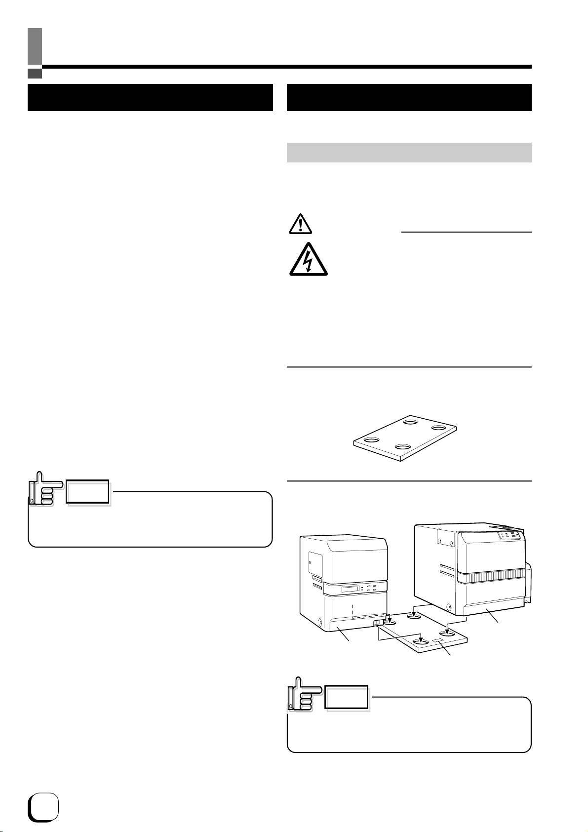
Do not place the machine on a rickety table or
slanting places.
• The machine may fall out of the table or fall over, which may
damage the machine or injure you.
• If the machine is damaged by falling or turnover,
immediately turn off the power, pull out the power plug, and
ask your dealer to repair. Do not try to repair it by yourself. It
is dangerous.
Do not wet the machine with water.
• Using the machine at a place where water splashes on the
machine, or wetting the machine with water (applying,
throwing, or spilling water over the machine) may cause a
fire or electric shock.
• If water entered into the machine, immediately turn off the
power, pull out the power plug, and ask your dealer to repair.
Do not try to repair it by yourself. It is dangerous.
Do not touch the machine with wet hands.
• Touching the machine with wet hands may cause an electric
shock.
Do not touch the power plug during electrical storms.
• Lightning may cause an electric shock.

6
Notes for safe operation (continued)
Pull out the power plug before cleaning the machine.
• This is for preventing electric shocks.
Pull out the power plug when you won’t use the
machine for a prolonged period of time to assure
safety.
• Remove the power plug from the outlet for safety when you
won’t use the machine for a long time.
Do not move the machine with the power cable and
other electric cables connected.
• The cables may be damaged while being moved, which may
cause a fire or electric shock.
• You may stumble over the cable and get injured.
Do not move the machine with objects placed on it.
• They may fall on you and hurt you.
Do not put heavy objects on the machine.
• They may fall on you and hurt you.
Do not block the vents.
• Heat generated inside the machine cannot escape, which
may cause a fire.
Inspection
• Ask you dealer or a qualified person to inspect the machine,
typically once every two to three years. Operating the
machine with dusts piling on the components for a prolonged
period of time may cause a fire or a malfunction of the
machine. It will be particularly effective to inspect the
machine before wet rainy season. Consult your dealer on
the costs of inspection.
Do not put the machine at a place where it will be
wet with steam (e.g., from a humidifier), or at a
excessively humid or dusty place.
• The oil, water and dusts act as conductors, which may
cause a fire or electric shock.
CAUTION
Ground the machine with the attached electric cord
when connecting it to the utility outlet.
• Using a cord other than the one supplied for grounding may
cause an electric shock when the machine fails.
Do not put your head or yourself into the packaging
bag.
• Do not play with the packaging bag. You may suffocate
yourself.
• Give close attention to small children who may want to play
with the packaging bag.
Do not use the machine while it has a fault.
• Do not use the machine while it has a fault, as this may
cause a fire or electric shock.
• Immediately turn off the power, pull out the power plug, and
ask your dealer to repair. Do not try to repair it by yourself. It
is dangerous.
Do not put the machine at a place where it becomes
excessively hot.
• The surface and internal components may deteriorate. Also
there is a danger of a fire. Special care should be taken for
exposure to direct sunlight or a heater adjacent to the
machine.
Hold the body of the power plug when pulling it out.
• Do not pull out the plug by holding the cable. The cable may
be broken or damaged which may in turn cause a fire or
electric shock.
Do not touch the power plug with a wet hand
• You may get an electric shock.
Do not lay the power cable near the heating
equipment.
• The covering of the cable will melt due to heat from such
equipment, which may cause a fire or electric shock.
Be careful of jamming your hand or fingers in the
card cassette or printer door.
• Replace the ink ribbon or remove jammed cards with care
not to jam your hand or fingers in the mechanism, which
may cause an injury.
Do not use a power cable other than the specified
cable for connection.
• If you use an unspecified power cable for connection or
extension, heat may accumulate in the cable, causing a fire.

7
Before use
Printer Characteristics
This card printer prints high quality full-color images
equivalent to photographs using dye sublimation printing
on standard-size (I O7810 compliant) PVC cards.
Printing can be done on both sides of the card.
Able to print maximum of 180 cards per hour. (For
tandard mode and single-sided printing)
Able to add on laminating function by connecting to
the optional Laminator unit (ILU).
Checking Accessories
Check the accessories that come with this printer when
unpacking.
tartup Guide (this book) x 1
*Besides this book, Instruction Manual (electronic
instruction manual) is available on the attached CD-
ROM.
Attached CD-ROM......................................... x 1
Power Cord:
AC 120V type (For North America)(250cm)x 1
AC 200V type (For Europe)(250cm)........... x 1
*The supplied power cord, instruction manual and
attached CD-ROM vary depending on the shipment
destination and product model.
Cleaning Card (for card transport roller) · · · · x 1
Card tacker · · · · · · · · · · · · · · · · · · · · · · · · · x 1
Ink Ribbon Cassette · · · · · · · · · · · · · · · · · · · x 1
Card Cassette · · · · · · · · · · · · · · · · · · · · · · · · x 1
Cleaning Unit · · · · · · · · · · · · · · · · · · · · · · · · · x 1
Protection Card · · · · · · · · · · · · · · · · · · · · · · · x 1
U B Cable(200cm) · · · · · · · · · · · · · · · · · · · · x 1
Content of Attached CD-ROM
Instruction Manual (Electronic)
DCP360i Printer Driver
DCP360i tatus Monitor(Printer Monitoring/ etup Tool)
DCP360i Printer Driver Instruction Manual
DCP360i tatus Monitor oftware Instruction Manual
Protection of Color Part
Be sure to carry out protective layer (OP) printing or
laminating in order to protect the print part that performs
color (YMC ink) printing.
Handling the Ink Ribbon and Card
Cautions for Handling
Pay attention to the following when handling the ink ribbon
and card.
• Use of distorted or damaged card will result in card
transport error.
• Touching the ink ribbon or printed surface of the card
directly with your hand will result in uneven print density.
• Attachment of foreign objects to the printed surface may
result in missing prints.
Change or replenish your ink ribbon and card in a clean
environment.
• Electrostatic discharge on the ink ribbon and card may
result in errors. Refrain from activities that will generate
static electricity, such as rubbing the cards.
• When replacing or replenishing old ink ribbons or cards
with a new one that is stored under a low temperature,
leave it for more than one hour in the ambient temperature
where the printer is used. Using it directly will result in
condensation, causing printing error and breakdown.
torage Method
The storage conditions of ink ribbon and card can greatly
influence the print quality. Choose the following type of
places for storage.
torage environment
Temperature: 5 °C to 25 °C
Relative humidity: 40 % to 60 %
torage Place
Avoid storing at the following places as it may result in
ink ribbon and card degradation.
• Locations with direct sunlight
• Locations with high temperature and humidity
• Locations near organic solvent and diazo copying machine
torage period
Ink ribbons should be used within a half year of
purchase. For cards, please consult the dealer from
which they are purchased.

8
Before use (continued)
torage and Handling of Card After Printing
Avoid storing at locations with direct sunlight, high
temperature and humidity.
Contact with the following chemicals and stationery may
also result in discoloration or fading of the card.
• Organic solvents such as alcohol, film cleaner and diazo
copier.
• oft PVC file, document case, pass holder, eraser, etc.
• Hairdressing products, cosmetics, etc.
Purchase of Ink Ribbon and Card
Consult your dealer for any queries regarding the ink
ribbon and card.
Make sure to use parts as specified below.
Ink Ribbon
Use only specific ink ribbons.
Refer to the page 33 on “Optional Items” in this manual
for the product names.
We do not bear any responsibility for
problems occurred as a result of using ink ribbons other
than the types specified.
Card pecifications
I O/IEC 7810 type ID1 (dimensions) :
equivalent product
I O/IEC 7811-2 (Magnetic stripe) :
equivalent product
I O/IEC 7816 (IC card) : equivalent product
CAUTION
Depending on the material, some cards
may not be suitable for printing.
The use of contact IC cards other than the type specified
may result in breakdown of the thermal head.
Consult your dealer beforehand on the material and other
specifications of card to be used.
CAUTION
Version upgrade
The following defects may occur as a result of the ver
sion upgrade for the firmware of the printer, the printer
driver and the DCP360i status monitor
• The operation of the printer or application software be-
comes unstable.
• Defects in print result occurs.
• Print color or shade differs.
• The performance of reproducing fine letters, changes.
• Others
Be sure to retain a copy of the current version when
performing version upgrade. Reinstall the previous ver
sion immediately if these problems occur. We are not
liable for any damage such as defective cards or inter
ruptions during printing as a result of the version up
grade.
Escape Clause
We do not provide compensation for any malfunction
during card printing caused by breakdown of the
machine, ink ribbon defects or card characteristics.
In addition, we also do not provide compensation for
insufficient print quality, which are not agreed in
advance. Please evaluate carefully beforehand.
Card Material
ome card material may not be suitable for printing.
Using a contact-type IC card other than those specified
by the dealer, may cause damage to the thermal head.
For details on the specifications about card material
or others, consult the dealer in advance

9
(When Printer Door is Open)
(Front / Right)
(Rear / Left)
Printer Door
Control Panel
Card Cassette (Accessory)
NG Card Outlet
Power Switch
Head Exchange Door
Card Stacker (Accessory)
aminator Connection Terminal
Filter Cover
Power Input Terminal
USB Cable Connection Terminal
Ink Ribbon Cassette (Accessory)
Cleaning Unit (Accessory)
Part Names

10
etting Up the Printer
Connecting the Laminator
An optional laminator is available for this printer. A special
connection cable is required to connect this unit. Consult
your dealer for more details.
etup
Location for Installation
The performance of card printers is greatly influenced by
the environment of the installation location.
Do not install at the following locations.
• Dusty Location
The cleanliness level of location where the printer
is used should be compliant with I O14611-1 Class
8. Different from the common type of paper printers,
dusty locations will result in uneven print density
and breakdown of the dusty thermal head. witch
off the printer’s power when no card is being printed.
Fine dust will be collected inside the printer after
leaving the power on for a long time, resulting in
uneven or dirty print.
• Locations with strong vibrations and shock
• Locations exposed to direct sunlight
• Locations where there is possibility of foreign objects
such as metal pieces entering the printer
• Locations against the wall with poor ventilation
• Unstable and inclined locations
• Locations which easily give rise to static electricity
such as carpeted rooms
• Locations which easily give rise to condensation
inside the printer such as places near the cooler,
humidifier or stove
Temperature and humidity of room where printer is
installed should be as follows.
Temperature : 15 °C to 30°C
Humidity : 35 % to 70 %
There are ventilation holes for cooling at the back of the
printer. Place back more than 10 cm away from the
surrounding wall. Additionally, ensure that there is at least
an allowance of 10 cm between the right end of the printer
and the wall so that cards can be discharged from the NG
Card Outlet. Do not place any object above the printer.
CAUTION
Using the printer in an environment
beyond the above range may cause printing problems due
to decrease in print density at low temperature and distorted
card and creased ribbon at high temperature.
CAUTION
If the mounting is uneven, the card will
not be transported smoothly. Be sure that the units fit in
properly. Always install the unit at a horizontal and hard
surface.
1. et up the unit coupler plate which comes with the
laminator (optional).
2. Insert the printer and laminator into the hole.
Electric
shock
WARNING
Install and uninstall the laminator only after
switching off the power of the printer as well
as other devices that are connected to it and
pulling out the plug from the power outlet.
Failure to do so may result in danger of
electric shock!
Use the dedicated unit and cable when
installing the laminator. Failure to do so may
result in breakdown or electric shock and fire.
Front
Laminator
(ILU)
Printer
(DCP360i)

3. Connecting a cable (optional) between units
Insert the cable into the “LAMINATOR” external connection
terminal at the printer and the “PRINTER” external
connection terminal at the laminator, followed by fastening
the cable with the screws provided.
Connecting the Power Cord
Use AVR (Automatic Voltage Regulator) when there is
possibility of voltage variation. Use of an uninterruptible
power source instead of AVR is recommended when there
is possibility of momentary power interruption.
AMINATOR
PRINTER
Printer
(DCP360i) Laminator
(ILU)
Printer
(DCP360i)
Connect the power cord to the power outlet in the same
way when connecting the laminator.
CAUTION
Always use a dedicated power supply
with earth terminal for the power outlet.
etup (continued)
Mounting the Card tacker
Pull the tab of the Card stacker at the stacker mount of
the printer.
The card stacker can hold about 100 cards that are
0.76mm in thickness.
Card Outlet
Printer
(DCP360i)
Card tacker mount
Card tacker
(Accessory)
Laminator
(ILU)
When connecting the laminator, pull the tab of the card
stacker at the stacker mount of the laminator card.
Ejection of Card
A properly printed card will be ejected to the card stacker.
If cards remain inside the printer when the power is on or
the printer is being initialized, or if some abnormal situation
occurs with magnetic cards or IC cards, those cards will
be ejected from yhe N.G. Card Outlet on the right side of
the printer.
2. Insert the power cord into the power input terminal
at the back of the printer, followed by plugging the
other end to the power outlet..
1. Check the plug.
•For AC 120V type • For AC220-240V type
(North America) (Europe)
* The detached power cords vary according to model
and country of purchase.
11

12
etup (continued)
etting the Ink Ribbon
1. Place your fingers on top of the printer door and open
towards you.
Open slowly while supporting with your hands.
2. Remove the ink ribbon cassette
(1) Hold the release lever with fingers, and 2 lift the lever
to unlock.
* Exchanging ink ribbons:
Upon ensuring that the ink ribbon is pulled out by about 3
cm, turn the knob on the ink ribbon cassette in the direction
indicated by the arrow to tighten the ribbon sag.
Remove the ink ribbon cassette while supporting it with
both hands.
tand the ink ribbon cassette on a flat and firm surface.
Remove any used ink ribbon.
CAUTION
Do not touch the inked surface with your
hands.
CAUTION
Do not install the ink ribbon on top of
the printer door. Do not rest your elbow or place heavy
objects on top. Doing so may damage the printer door.
2
1
Release Lever
Unlock
CAUTION
When the ink ribbon is installed, be
careful not to drop it into the inner section when pulling out
the cassette.
CAUTION
When removing the cassette for
cleaning, always stand it as shown in the photo below.
Allowing the inked surface to touch the ground will make
the ink ribbon dirty and cause malfunction.
Knob
Remove ribbon sags
Remove ink ribbon cassette
haft
Bobbin holder
(Taking up)
haft
Bobbin holder
(Unused)

13
Inserting ink ribbon cassette by force
when the guide shaft is not properly placed in the guide rail
may damage the device.
CAUTION
If the ribbon sags, it will result in jammed
ink ribbon and blurred color caused by wrinkles when the
ink ribbon cassette is inserted.
CAUTION
4. Remove ink ribbon sags
Turn the taking up bobbin in the direction of the arrow to
remove any ink ribbon sag.
5. Insert ink ribbon cassette along the guide rail
While making sure that the ink ribbon does not sag, insert
the ink ribbon cassette all the way in along the guide rail
and push down the lever to lock the ink ribbon cassette.
If it is not so smooth to push down the lever, pull out the
ink ribbon cassette once ,insert it again and push down
the lever while pushing the ink ribbon cassette.
3. Insert ink ribbon into the ink ribbon cassette
With the inked surface facing the outside (inner side rolled
into the bobbin holder), stretch along the 3 shafts and
insert all the way into the bobbin holder.
Ensue to fit the ink ribbon
cassette shaft firmly into
the guide rail.
Guid rail
etup (continued)
CAUTION
To prevent damage, the printer door is
made in such a way that it cannot be closed properly when
the ink ribbon cassette is not locked or when the ink ribbon
cassette is not inserted. Closing the printer door by force in
such a case may damage the device.
7. Checking
When ink ribbon is changed with power on, the printer
will automatically initialize once the printer door is closed.
If printer power is off, it will start to initialize once it is
switched on.
Check that initialization is carried out properly and the
READY LED (green) is illuminated on the printer control
panel.
6. Close printer door.
hut the printer door tightly by pressing on the top right
section of the printer door.

14
etup (continued)
Adjusting Card Thickness
This printer can print cards with thickness between 0.25
mm to 1.00 mm. Default thickness is adjusted to 0.76mm.
1. Remove card cassette
Lock the card cassette cover by moving the slider on the
top of the card cassette to LOCK.
Lift the card cassette up by about 1cm and slide to the
right to remove the cassette.
2. Adjust the Card separator
Insert the tip of a ball pen etc, into the hole on Card
separator of the card cassette and turn slowly to adjust to
the thickness of your card.
1
2
Card separator
Ball pen etc.
CAUTION
tains such as fingerprints on the printed surface will result
in printing error. Use lint-free gloves (optional) when
handling the card.
Insert the card in an environment that is not subject to
excessive dust.
1. Removing card cassette cover
Unlock by moving the slider on the top of the card cassette
to OPEN. Lift the cover.
etting the Card
Get ready the specified cards from your dealer.
lider
Cover
Top View of Printer
Front View of Printer
During printing, when the card is not discharged from the
card cassette, adjust the Card separator adjustment position
clockwise, one scale at a time. If 2 cards are discharged,
adjust the Card separator adjustment position anti-
clockwise.
When cards of different thickness are used frequently, it
is recommended that you purchase an additional card
cassette based on the thickness of the card. Refer to
Optional Items (see p.33) regarding purchase of card
cassettes.

15
CAUTION
Cover cannot be closed properly if the
cards are not properly aligned. Check to ensure that they
are properly aligned.
2. Insert card
Card cassette can hold about 100 cards of 0.76mm in
thickness.
CAUTION
Cover cannot be closed if too many
cards are inserted. Check to ensure that they are kept below
the MAX line.
CAUTION
When using a new card from the box,
the cards may stick together due to static electricity. In such
a case, separate the cards piece by piece before setting
them. Alternatively, operate while holding the edge of the
card.
Max line
Max line
Properly
Properly
aligned
aligned
CAUTION
Be careful not to catch your fingers
when attaching the cover.
4. Covering the card cassette cover
Mount from the top, following the cassette guide.
CAUTION
The cover may not be closed if the
cards are not properly aligned. Closing the cover by force
in such a case may damage the device.
Memo
When using the pre-printed cards, refer to the
instruction manual of the host computer’s operational
software on procedures to insert the card.
Cassette guide
CAUTION
Feeding without closing the cover will
result in printing malfunctions such as jammed cards and
adhesion of foreign particles. Always feed with the cover
closed.
etup (continued)
3. Put the protection card on the cards with the
polished side of the protection card up.
Protection Card
To avoid card feeding jam, the number
of cards to be set in the cards cassette shall be less than
100pcs. For example, if 0,25mm thick cards are used, the
top of the piled cards should be lower than the level marked
as 40.
CAUTION
The protection card shall be put on the
top for any kind of cards.
CAUTION

16
CAUTION
We do not guarantee printing onto
magnetic stripes.
Do not print on the magnetic stripe as it will cause failure in
reading and writing the magnetic data.
CAUTION
When using a card with both magnetic
stripe and contact-type IC, insert card by using the IC side
as the reference side.
et IC terminal to printer’s inner top or inner bottom.
When Using a Contact-type IC Card
When using a contact-type IC card, set to any of the
following according to the layout.
I O MG Optional Model
JI MG Optional Model
et IC terminal to printer’s front top or front bottom.
et with magnetic stripe on the top right or bottom left.
When Using a Magnetic Card
When using a magnetic stripe card, set to any of the
following according to the layout.
etup (continued)
upply of Card
upply of card can be performed when the READY LED
(green) on the control panel, or when the CARD LED (red)
is illuminated.
upply of card is also possible when the power is off.
upply of card can be performed during printing, but we
advise it to be done when printing is not in progress as
feeding without cover may result in printing malfunctions
such as jammed cards and adhesion of foreign particles.
upply card carefully to avoid
interruptions during printing and printing errors caused
by vibrations while opening and closing the card
cassette.
CAUTION

17
etup (continued)
Connecting the U B Cable
CAUTION
Adjust orientation of the U B cable
according to the terminal, and insert it all the way in.
1. Check to ensure that the power of both the printer
and host computer are switched off.
2. Connect the printer and host computer with the U B
cable.
Insert the U B cable to the U B cable connection terminal
at the back of the printer.
Printer
(DCP360i)
CAUTION
Consult your dealer on the cable
connection if there are U B or serial cable connection
terminal on the printer’s optional port.
CAUTION
The location of terminals varies with the host computer.
Please refer to the instruction manual of the host
computer.
When there are multiple U B cable comection terminal
on the host computer, either one can be used.
Do not connect to the U B comection terminal on the
host computer’s monitor or keyboard. It may not be
recognized correctly.
When using a U B hub, connect to the hub that is directly
linked to the host computer.
Connecting Multiple Printers
When connecting a host computer to multiple printers,
set different Unit Numbers from 1 to 7 for each printer.
etting can be done at the printer’s control panel.
Unit number is not necessary when only 1 printer is being
connected.
1. et printer to Unit number etting Mode
witch on the power while pressing the CLEAN button on
the control panel. READY LED (Green) and ERROR LED
(Red) will be lighted when the CLEAN button is released.
Upon pressing the RE ET button on the control panel,
the READY LED (green) starts to blink and the current
unit number will be displayed. There are 3 status, namely
ERROR LED (red), CARD LED (red) and INK LED (red)
for each unit number, which are shown as in the following
diagram.
* Initial value: 1
LED tatus and Unit Numbers
2. et Unit Number
1 new Unit number will appear every time the RE ET
button on control panel is pressed. Press the CLEAN
button to save the setting when the Unit number that you
wish to set appears. The READY LED (green) only will
change from blinking to lit when it is saved. To change
again, press the RE ET button to return to the setting
mode.
3. witch off the power
CAUTION
In order to connect to multiple printers,
setting will be required for the printer driver in use as well
as for the card issuance software. Do so by referring to the
respective manuals.
Unit No.
ERROR
CARD
INK
1 2 3 4 5 6 7
blink Light off
CAUTION
Do not switch off the power of the host
computer during printing, and do not use the suspend
function on the host computer.
If the power of the host computer is switched off during
printing, or if the suspend function of the host computer is
activated, cards printed halfway may remain in the printer.
When this occurs, open the printer door and close it again.
Cards remained in the printer will be ejected from the NG
Card outlet.

18
Installation of oftware
About software
The following softwares are required in order to use
DCP360i. These are kept in the attached CD-ROM.
(1)DCP360i Printer Driver
Install the printer driver from the attached CD-ROM
when using DCP360i printer drivers. Refer to the
electronic file in the CD-ROM “Printer Driver Install
Manual” for method to install. Refer to the respective
guide books on the use of other printer drivers.
(2)DCP360i tatus Monitor
oftware that carries out various settings and indicates
the status of DCP360i. Install into the host computer
that connects to DCP360i.
Operation Environment
oftware in the attached CD-ROM operates in the
following environment.
Windows® XP Professional and Home Edition
Windows® 2000 Professional
Connecting to the Host Computer
oftware Licensing Agreement
Before using the software contained in the CD-ROM
supplied, please read through the “ oftware Licensing
Agreement” at the end of this manual.
You will not be allowed to use this software unless you
have agreed to accept the terms stated in the agreement.
When installing the software, log-on
shall be done by a qualified user(Administrators Group).
CAUTION
Installation of DCP360i Printer Driver
When the message “connect the U B cable to the printer”
appears on the screen,connect the U B cable.
Refer to the electronic file “Printer Driver Install Manual”
(Install PRD01∗.PDF) stored in the folder “English/
Document” ,and install the printer driver.
CAUTION

19
Checking Connection with the Host Computer
Check the printer and software operation after installing the U B driver and DCP360i status monitor.
1. Check to ensure that the printer is connected to the
host computer.
2. witch on the power for the printer and host
computer.
3. tart up the DCP360i status monitor once the host
computer is booted up.
4. Check that the printer is ready from the printer status
display (Diagram A) on the DCP360i status monitor.
5. elect B to display others screens and carry out
test printing.
1Check the connection between the printer and host
computer when the “No printer is found.” message is
displayed.
2If “Initializing” is displayed, wait till the “Ready” message
appears.
3Display of other messages indicates that failure has
occurred. Refer to “Cause and Action for Error Code”
on page 25 of this manual.
tatus Display creen
Others creens
1elect “Both ides” for test printing and click on the
Print button.
2Print a card with the picture below on both sides.
Operation check for the printer and installed software is
now complete. For actual printing of cards, refer to the
manual of the card issuance software or printer driver in
use.
B
A

20
How to read the Instruction manual (electronic manual)
An instruction manual (electronic manual) is included in the attached CD-ROM. To view the
manual, you need to install Adobe Reader (Ver6.0 and above) on the host computer. Adobe
Reader can be downloaded free-of-charge from Adobe’s website.
You can either open the instruction manual directly from the CD-ROM or copy it to the hard disc
of the host computer.
Content of the Instruction Manual (electronic manual)
•Operating the Printer
LED Display
Names of Various ections on control panel
Button Control
Initialization
Test print using the printer alone
•Differences between printing modes
•How to Use the tatus Monitor
creen Configuration
Monitoring Printer tatus
Ready tatus Display
Error tatus Display
Other tatus Display
Changing Printer ettings
Checking the Media and Printing tatus
Display When Ink ribbon is Unknown
Checking Printer Configuration
Resetting the [No. of Cards Issued] Item
Test Printing
Upgrading Firmware
•Troubleshooting (detailed version)
Internal Configuration
List of Error Codes and Corresponding Actions
When ink ribbon is torn
Problems Related to Printing
Problems related to Color Printing
Problems Related to Text Printing
Problems Related to Protective Layer(OP)
Actions to Take When Printer Fails to tart Up
•Version upgrade
•pecifications
Main pecifications
External Dimension
Other manuals for DCP360i
1
Table of contents
Other EDISecure Printer manuals