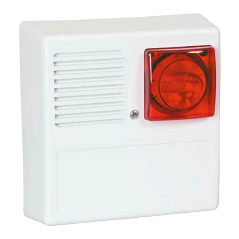
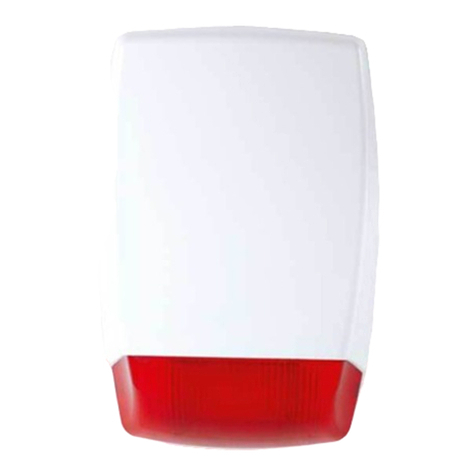
EDS EWS User manual

EWS
ALARM SYSTEMS
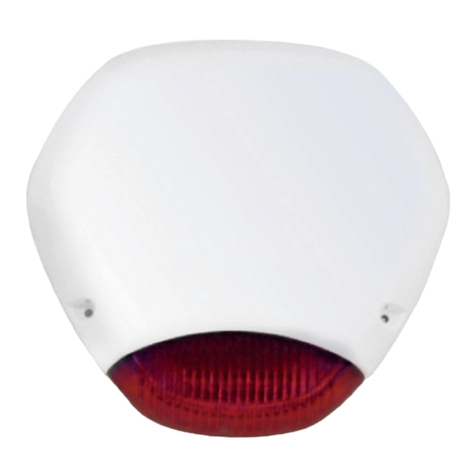
WIRELESS OUTDOOR SOUNDER
User Manual & Warranty Certicate
www.edselectronic.com

1
It is designed for use in outdoor environments.
Normally, there are 2 running warning LEDs.
It is suitable for communication with 868 MHz frequency wireless
panel.
In the event of an alarm, it gives a visual warning with 2 powerful
flashers and an audible warning at a minimum 106 dBm level.
There is a cover and base tamper protection.
Tamper errors, low battery error, communication failure, Sounder
alarm status can be remotely monitored.
The alarm sounder duration can be selected as between 5 and 15
minutes.
An “Observe” signal is sent in every 18 minutes. If the panel does not
detect the observation signal during 18 minutes, a communication
error is generated.
Built-in, self-powered, wireless outdoor sounder
BRIEF DESCRIPTION OF THE OPERATION
1
TYPE OF WARNING DEVICE
2

2
LED Flasher
1
1
DIMENSIONS
3
210
320

3
TECHNICIAL SPECIFICATIONS
4
Model EWS
Environmental class IV Outdoor
Security level Class 2
Electrical
Nominal voltage 7.5V DC
Supply voltage range 4.2V-8V DC
Low battery limit 4.2 VDC
Standby current <2mA
Alarm current <110mA
Voice output 106.13 dB @8V 1m
Voice frequency 3.3-3 kHz
Voice type 1
Sounder ringing time is 5/15 minutes. Selectable
Buzzer Single Piezo
Flasher LED Flasher
LED indicator Running LED indicator
LED indicator color Blue
Tamper switch Available against wall removal and cover opening

4
Communicaton
Frequency 868MHz
Supervisor time <18 min.
Battery
Battery type Non-rechargeable
Battery life >3 years
Embedded battery 7.5V 17000 mAh, LR20, type D battery
General
Housing material ABS Plastic
Housing shape Standard
Housing color White
Protection class IP 65
Operating temperature 0 0C / +50 0C
Dimensions (HxWxD) 320x210x80 mm
Weight 1.4 kg
Year of Manufacture The year and week of manufacture is included in the first four digit of
your product serial number (located on the product identification label)
Manufacturer
EDS Elektronik Destek Sanayi ve Ticaret Ltd.
Meclis Mah. Teraziler cad. Hayran sok. No:4 34785
Sancaktepe / İstanbul / Turkey
Recycle

5
ELECTRICAL CONNECTIONS
5
Figure 1: Sounder Main Board
Jumper Position Meaning
JP1 -
JP2 Inserted Entering the
memory reset
procedure
JP3 Inserted
JP4 Inserted
JP5 Inserted 15min. alarm
Not Installed 5min. alarm
JP6 -
1
2
3
4
5
6
7
8
9
Memory Reset Jumpers
The alarm time is 5-15 min. Jumper
for select 5 not plugged in Jumper
for 15 plugged in
SW Tamper Connection
Buzzer
Battery
Flasher LED
LED 1
LED 2
Keys (S1)
1
2
3
4
5
6 6
78
9
3
4
5
6 6
78
9
1
2

6
In the assembly, install the Sounder with 3 screws and dowels. The screw
and dowel used should be compatible with the external environment. Since
the use of 3 screws and dowels will ensure the device to be fixed properly, it is
especially recommended to be used.
20m maximum to the alarm control panel. It is recommended to be mounted
away
To open the cover, the Sounder is placed on a flat surface.
MESSAGES AND DEFINITIONS
Recommended mounting conguration, xing methods,
prohibited areas, mounting location and location features
6
7
INTRUSION
When the PIR detector detects motion in the environment, it sends
the Intrusion information, and when the Intrusion is removed, sends
information for removal of intrusion.
SABOTAGE
In case of sabotage, a tamper status signal is sent to the control
panel. In addition, if the Sounder is registered on the panel, the
Sounder gives an audible and visual warning when sabotage occurs.
Audible and visual warning continues from the panel until the alarm
is resolved or the alarm time of the Sounder expires.
ERROR
MESSAGE
When the battery voltage drops below 4.2V, low battery information
is sent to the main panel.
SELF
TEST
It is checked whether the buzzer and flasher LEDs work or not.
Failure information is transmitted to the panel in case of any
malfunction.

Installation can be made from the places shown with B and C in Figure 2.
Before installation, place the bottom plastic with the help of the template in
the cardboard box and determine the screw and hanger location on the wall.
As indicated in the template, there are 3 screws and 1 hanging point B and
1 cable transition terminal D for cable connection.
By pushing towards the upper part of the cover, the tabs on the upper cover
are released and the cover is removed.
Open the storage box.
Take the top cover mounting screw A.
Make the battery connection. When connecting the battery, pay attention
to its directions.
7
Figure 2 : Sounder interior view
Top cover mounting screw
Hanger location
Mounting holes
Cable transition terminal
Battery
Protective cover location
Cover mounting location
Transparent protective cover
A
D
G
B
E
I
C
F
A
D
G
B
E
C C
C
C
F

7.1. Placing the Protective Cover
The electrical connections of the card; do as shown in the electrical
connection section.
After the programming mode is completed and the electrical connections
are completed, place the transparent protective cover on the PCB board as
shown in the figure (Figure 3).
7.2. Attaching and Screwing the Top Cover
As shown in Figure 4, place the 1 tabs so that they
enter the 2 slots on the bottom cover and fit the
top cover. Fix the cover with the screw A protruding
from the inside of the Sounder and fix it to the
mounting location G.
Important: After completing the programming mode, continue with the
assembly procedure.
Figure 3: Placing the transparent
protective cover on the PCB board
Figure 4: Attaching and
screwing the top cover 8
G
1
2
1
2
H

Important: After the installation process is completed, the first installation
process can be started. Please do not close the cover before the automatic
learning process ends.
7.3 Opening the Top Cover After Its Installation
Remove the screw at G point in Figure 4 with the help of a screwdriver.
By pushing towards the upper part of the cover, 1 tabs are released and the
cover is removed.
7.4 Sheet Cover Assembly
The optional Sheet Cover is mounted as shown in the figure (Figure 5).
Figure 5: Sheet Cover Assembly
9

8.1 Programming Mode
Turn on auto-learn mode from the panel
Open the cover of the detector
Place the battery in the battery chamber inside the Sounder
When the automatic learning is completed, LED1 and LED4 on the device
will blink 3 times. In addition, an audible notification will be heard from the
panel that the device has been identified.
With this process, the Sounder has been introduced to the panel.
8.2. Registration Deletion
If the Sounder will be introduced to a different panel, it must first be deleted
from the panel it is defined. To do this, follow the steps below.
Open the sounder cover
Remove the battery from the battery holder.
Attach the memory reset bridge elements named JP4, JP3, JP2
(Figure 1).
Notes:
If you have inserted the battery before the auto-learn mode is turned on,
you can introduce the Sounder to the panel by pressing the sabotage (SW)
button.
If you want to delete the Sounder from the panel, please follow the delete
procedure.
Memory deletion can be performed by following the 8.2 items.
MESSAGES AND DEFINITIONS
8
10

Put the battery back into the battery compartment. Keep your hand close
to the “S1” button.
When LED1 and LED4 light up, press the “S1” button.
When LED1 and LED4 turn off, release the “S1” button.
Repeat this process as LED1 and LED4 flash, until you see the success or
failure sign.
If the operation is successful, LED1 and LED4 will blink quickly. If the
operation is successful, you need to remove the Memory reset bridge
elements (JP4, JP3, JP2).
If the operation fails, the blue LED1 and LED4 will gradually blink slowly.
In this case, please repeat the deregistration process.
Important: Memory reset bridge elements should definitely be removed after
the process is finished.
8.3. Battery Replacement
When the battery low warning is received from the panel, please replace the
battery in the Sounder as soon as possible.
Open the Sounder cover.
Remove the battery from the battery holder.
Install the new battery.
Test by pressing the Status LED on the panel.
11

RF OUTPUT POWER
9
RF Output Power can be selected manually or in automatic mode, the device
can make its own choice of signal level. Please refer to the user manual of the
alarm control panel for this setting.
Notes:
Manually adjusting the RF output power may cause communication problems
between the detector and the panel. High power RF output power settings
may result in a reduction in battery life.
12
RF Level Value
5th level (max. broadcast power) 11,48 mW
4th level 6,6 mW
3rd level 3,54 mW
2nd level 1,82 mW
1st level 1,15 mW

13
RECYCLE
10
You could send your old devices back to our company for free recycling.
The above symbol indicates that this product and / or battery must not be
disposed of with household waste.
When your device has reached the end of its useful life, contact your local
authority for disposal and recycling options, take it to a collection point for
the recycling of electrical and electronic equipment, or hand it over to EDS
Elektronik.
This product does not contain harmful or prohibited substances specified in
the Regulation on the Control of Waste Electrical and Electronic Equipment
issued by the Turkish Republic Ministry of Environment and Urbanization.
Complies with WEEE regulations.
The above symbol means that your product and / or battery must be disposed
of separately from household waste in accordance with local laws and
regulations. When this product has reached the end of its useful life, hand it in
at the collection point indicated by your local authority. The separate collection
and recycling of your product and / or battery at the time of disposal will help
to conserve natural resources and ensure that it is recycled in a manner that
protects human health and the environment.
European Union

14
The terms of the warranty is valid for products sold in Europe Union.
Failure to occur during loading, unloading and shipment after delivery of
the goods is not covered by the warranty.
Damage, malfunction and information services caused by operating errors
are not covered by the warranty.
Damage and malfunctions due to low or high voltage, faulty electrical
installation, voltage other than the voltage indicated on the product label are
not covered by the warranty.
Failures and damages resulting from natural disasters
(earthquake, flood, etc.), fire and lightning are not covered by the warranty.
The warranty is void if the document is tampered with and the original
serial number is removed.
WARRANTY CERTIFICATE
11

WARRANTY CONDITIONS
1. The warranty period starts from the delivery date of the product and is for
1 year.
2. The product is completely under the warranty scope of our company
including all the pieces.
3. In case of the product’s breaking down within the warranty period, so the
repair period is added to the warranty period. The maximum repair period of
the product is 20 working days. This period starts from the notification date
of the product’s failure to the service station and in default of the service
station, so one of those as the product’s seller, dealer, agent, representation,
importer or importer-producer. If the product is not troubleshot within 10 days,
the importer-producer or importer must assign another product within similar
properties to the use of the consumer till the product’s repair is completed.
4. In case of the product’s breaking down within the warranty period either
due to material and labor, or mounting failures; then the repair shall be made
without requesting any charge as labor cost, shanged part fee or under any
name.
5. Despite the consumer uses the repair right;
5.1. Since the product is delivered to the consumer and provided that being
within the warranty period, if the same failure repeats more than two, or the
different failures occur more than four, or the total elements of the different
failures exceed six times within the specified warranty period in one year, as
well as these failures perpetuate not to benefit from the product,
5.2. If the maximum period required to repair is exceeded,

5.3. In the situations of the determination that the failure’s repair is impossible
with a report to be issued by the firm’s service station and in the unavailability
of the firm’s service station, respectively by one of the seller, dealer, agent,
representation, importer or importer-producer; the consumer can request the
free change of the product, refund or price discount at defection rate.
6. The failures arising from the use of the product contrary to the particulars
in the user’s manual are outside the scope of warranty.
7. For the problems to be arisen regarding the Warranty Certificate, you
can apply to the Directorate-General of Consumer Protection and Market
Surveillance of the Ministry of Customs and Trade.
Üreticinin ünvanı / Servis adresi:
EDS Elektronik Destek San. ve Tic. Ltd. Şti.
Meclis Mah. Teraziler Cad. Hayran Sok.
No:4 34785
Sancaktepe/İstanbul/Turkey
Tel: 0216 528 45 00 Fax: 0216 314 17 80

PRODUCT INFORMATION
Type of Product : Wireless Outdoor Sounder
Brand : EDS
Model : EWS
Serial No and Bandrol :
Warranty Period : 2 years
Maximum Repair Time: 20 days
Product liftetime : 5 years
Delivery date and place:
Title
Address
Phone
Fax
E-mail
Title
Address
Phone
Fax
E-mail
Date and Number of Invoice
Delivery Date and Place
: EDS Elektronik Destek San. ve Tic. Ltd. Şti.
: Meclis Mah. Teraziler Cad. Hayran Sok.
No:4 34785 Sancaktepe/İstanbul/Turkey
: 0216 528 45 00
: 0216 314 17 80
: [email protected] - www.eds.com.tr
:
:
:
:
:
:
:
Saller
Stamp / Signature:
Producer
Stamp / Signature:
MANUFACTURER SELLER COMPANY
2113
Technical specifications are subject to change without prior notice.
Scan this code with your
smartphone to visit
www.edselectronic.com
Table of contents
Other EDS Security System manuals