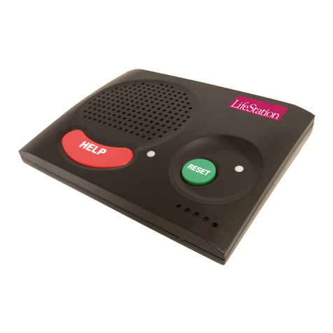
Climax CH-MG Operating instructions

CH-MG
Cellular Home Alarm System
Installation and Operation Guide
3Dec2020

Table of Contents
1.INTRODUCTION..................................................................................................................1
1.1.CH-MG.................................................................................................................................1
1.2.WHAT’S IN THE BOX..............................................................................................................1
2.SYSTEM OVERVIEW..........................................................................................................2
2.1.IDENTIFYING THE PARTS.......................................................................................................2
2.2.POWER SUPPLY....................................................................................................................3
3.GETTING STARTED – SETTING UP CH-MG....................................................................4
3.1.INSERT A SIM CARD..............................................................................................................4
3.2.LOCATING A SUITABLE POSITION FOR THE CONTROL PANEL...............................................4
3.3.HARDWARE INSTALLATION (FOR PC PROGRAMMING)........................................................5
3.4.SOFTWARE INSTALLATION (FOR PC PROGRAMMING).........................................................6
3.4.1.Installing USB Driver...................................................................................................6
3.4.2.Installing PC Programming Tool..............................................................................6
4.PROGRAMMING CH-MG....................................................................................................7
4.1.PC PROGRAMMING TOOL (INSTALLERS ONLY)...................................................................7
4.1.1.SMS Program................................................................................................................9
4.1.2.APN..................................................................................................................................9
4.1.3.Wi-Fi..............................................................................................................................10
4.1.4.Report...........................................................................................................................10
4.1.5.Setting...........................................................................................................................15
4.1.6.Device...........................................................................................................................17
4.1.7.Telemetry Log.............................................................................................................18
4.1.8.System Log.................................................................................................................18
4.1.9.Miscellaneous.............................................................................................................19
4.1.10.Firmware......................................................................................................................20
4.2.SMS REMOTE PROGRAMMING...........................................................................................21
5.LOCAL RF DEVICE MANAGEMENT...............................................................................22
6.OPERATION.......................................................................................................................23
6.1.ANSWERING INCOMING CALLS...........................................................................................23
6.2.CURRENT OPERATION CONDITION.....................................................................................24
6.3.TEST MODE.........................................................................................................................24
6.4.ALARM ACTIVATION............................................................................................................24
6.4.1.Callback Mode............................................................................................................26
6.4.2.Speech Reporting Method.......................................................................................26
6.4.3.Report Sequence.......................................................................................................27
6.5.CHECK PANEL STATUS.......................................................................................................29
6.6.VOICE PROMPTS.................................................................................................................30
7.APPENDIX.........................................................................................................................32
7.1.SMS REMOTE PROGRAMMING COMMANDS TABLE...........................................................32

1
1. Introduction
1.1. CH-MG
CH-MG is an indoor cellular alarm system with Wi-Fi and RF capabilities. It is
capable of playing voice prompts to raise the users’ self-awareness and
reporting events via Speech, SMS and IP (Mobile Network) protocols to
directly communicate with the monitoring centers.
CH-MG can be programmed by using programming software via RJ-11
connection, providing intuitive graphical interface for installers to program the
panel easily from a computer.
1.2. What’s in the Box
Your CH-MG package includes the following items:
Items
CH-MG
12V 1A Adapter
Programming Cable (Optional)

2
2. System Overview
2.1. Identifying the Parts
Button/LED/Component Behavior Function/Indication
1. White Backlight Dimly lit Idle/normal mode
ON Alarm Reporting
Flash During Guard time or
Retrying report
2. Help Button
Press once Activate alarm
Press once when CH-MG
is ringing
Pick up an incoming call
Press and hold for 5
seconds during a call
Terminate the call
3. Info Button Press once 1) Check cellular signal
strength, power status,
and system status via
voice prompt
2) Cancel Alarm
Press and hold for 3
seconds
Enter Test Mode
LED (Red) Flash During Guard Time
LED (Blue) 1 Flash every 2 seconds In learning mode
LED (Amber) 1 Flash every 3 seconds Panel Low Battery/ Cellular
Network fault/battery
disconnected
1 Flash every 5 seconds Device low battery/Device
tamper/Device out-of-order
LED (Green) ON AC power connected
Flash AC power disconnected
All LEDs ON During Local Firmware Update
4. Microphone
5. Speaker
6. Power Button Press the Power Button once to power on/off the panel.
7. DC Jack Connects to an AC-DC 12V/1A switching power adapter.
8. Micro SIM Card Slot

3
Button/LED/Component Behavior
9. Programming Telephone
Jack
The programming cable (QT cable A) needs to be plugged
into this jack and connected to a PC for PC Programming.
10. Volume Adjustment Button Press the button to adjust the volume level. 5 levels are
available for selection. Each button press will lead to next level.
The cycle of 1-5 will be repeated sequentially.
11. Learn Button Press and hold for 6
seconds in normal mode
Enter RF device learning
mode
Press once in learning
mode
Exit learning mode
2.2. Power Supply
An AC power adapter is required to connect to a wall outlet. Be sure only
to use an adapter with the appropriate AC voltage rating to prevent
component damage. A DC 12V output and 1A switching power adapter is
generally used to power CH-MG.
In addition to the adapter, there is a rechargeable battery inside CH-MG
which serves as a back-up in case of a power failure.
During normal operation, the AC power adapter is used to supply power to
CH-MG and at the same time recharge the battery. It takes approximately
72 hours to fully charge the battery.
After power is supplied to CH-MG, press the power button once to power
on the Control Panel.

4
3. Getting Started – Setting up CH-MG
3.1. Insert a SIM card
CH-MG Panel features built-in Cellular network communication facility to report
to the Monitoring Station.
To Insert SIM card:
It is recommended to disable the SIM card PIN code before inserting into
the Control Panel.
The SIM card base is located on the rear side of the unit. Insert the SIM
card with the chip side facing up.
Push to the furthest extend, then press on the edge of the SIM card firmly
to secure it.
SIM Card will delete its SMS messages whenever the CH-MG is powered
on.
To remove SIM card:
Press and release on the edge of SIM card, the card will spring out.
3.2. Locating a suitable position for the Control Panel
The Control Panel requires main power and a constant cellular network
reception.
The Control Panel should be easily accessible.
The Control Panel should not be placed in a damp location, such as a
bathroom.
The Control Panel should not be placed close to any heat source, such as
microwave ovens, which can reduce signal strength.
The Control Panel should not be located alongside other radio transmitting
devices, such as mobile phones, cordless phone, or wireless computer
network (Wi-Fi) devices.

5
3.3. Hardware Installation (For PC Programming)
Programming QT cable A
CH-MG has a QT cable A for PC programming (optional item, sold
separately).
Panel Connection
Step 1. Plug a DC 12V 1A power adapter into the DC Jack of your panel and
connect to power supply. Press the power button to power on the panel.
Step 2. Plug the QT cable A into the Programming Telephone Jack of CH-MG.
Step 3. Connect the the QT cable A to the USB port on your computer.
See Figure 1 for connection diagram between medical panel and computer.
See Figure 2 for CH-MG connection jack locations.
Figure 1
Figure 2

6
3.4. Software Installation (For PC Programming)
3.4.1. Installing USB Driver
CH-MG can be programmed via USB port connection of a computer using the
PC Programming Tool software (using the Programming Cable).
If the computer cannot recognize the USB connection, please try installing the
USB driver as instructed below.
Step 1. Make sure CH-MG is connected properly (please refer to 3.3.
Hardware Installation)
Step 2. Please go to http://www.ftdichip.com/Drivers/VCP.htm. Scroll down
the webpage and select the driver file according to your operation
system, download and install the driver.
3.4.2. Installing PC Programming Tool
PC Programming Tool for CH-MG is a portable application and requires no
installation. After installing the USB driver, simply unzip the file to a desired
folder and execute the “Mobile_Tool_MG.exe” file.

7
4. Programming CH-MG
CH-MG can be programmed by using a PC Programming Tool.
4.1. PC Programming Tool (Installers Only)
For system setting programming with PC Programming Tool software via USB
port, follow instruction below.
Step 1. Execute the programming tool:
The following configuration screen will be opened.
Step 2. Select the following settings in the top section of the configuration
screen and click “Open.”
Port: Select the COM port generated for CH-MG after installing
the USB Driver (the USB port connected to CH-MG).

8
Baud rate: 115200
Data: 8
Parity: None
Stop: 1
FlowCtrl: None
Step 3. Read Configuration
To start configuring CH-MG settings, click on “Open”. A Read configuration
success message will pop up, click “OK” to proceed:
The current CH-MG setting will be displayed. Click on different tabs to see and
edit CH-MG functions.

9
4.1.1. SMS Program
This tab allows the user to program SMS Keyword (15 characters max.) and
Access Code 1 (4-8 digits) which are used for SMS Programming feature.
Enter the information and click “Write” to complete programming. Please note
that SMS Keyword is case-sensitive. For detail information, please refer to 4.2.
SMS Programming.
SMS Keyword: PROG (default)
Access Code: 1111 (default)
4.1.2. APN
The APN setting must be completed for CH-MG to report events via cellular
network.
Click “APN” to set APN Name, APN User and APN Password and click “Write”
to confirm.
APN Name: The name of an access point for GPRS. Please ask your SIM
card service provider for your APN.
APN User: Offered by your SIM card service provider. Please ask your
service provider for your GPRS username. If no username is required, you
may skip this step.
APN Password: Offered by your SIM card service provider. Please ask
your service provider for your GPRS password. If no password is required,
you may skip this step.

10
4.1.3. Wi-Fi
The “Wi-Fi” tab allows the user to configure the panel’s Wi-Fi setting.
UUID: Enter the Wi-Fi network name.
Wi-Fi Password: Enter the Wi-Fi password..
4.1.4. Report
The “Report” tab allows the user to configure report settings.
CH-MG reports over 3 media: IP (Mobile Network), Speech channel, and SMS
message.
5 Report Indexes are available for setting:
4 programmable settings are available per Report Index:
1. Report Destination

11
Enter a report destination. The format of the report destination will depend
on the Reporting Format (Type). Please see Report Destinations below.
If there are no report destinations programmed, CH-MG will not report upon
alarm activation and will emit 1 beep as a reminder.
2. Event Filter
Select an event filter. The event filter determines which events are reported
to the selected Report Destination.
3. Reporting Format (Type)
Select a reporting format. The reporting format determines how the events
are reported to the Report Destination.
4. (Reporting) Groups
Assign the Report Index to a Reporting Group. The Reporting Group
determines the sequence of reporting.
Click “Write” to apply the settings to CH-MG.
Report Destinations
After Report Format is determined, enter the Report Destinations according to
the designated Report Format:
JSON reporting: http://iota.medicalguardian.com
JSON udi: Please input the device UDI (Unique Device Identifier) for
JSON Report. Maximum of 15 numeric characters or alphanumeric letters.
Speech reporting and SMS Text Report Format: PhoneNumber
Example: 0912345678
Speech Reporting: When activated, CH-MG will dial to the telephone
number and open two-way voice communication directly.
SMS Text Reporting: When activated, CH-MG sends a SMS text
message to the recipient. The message contains event information.
If two-way communication is required after an IP or SMS report, please
program a separate Speech Report. Alternatively, the user can also utilize
Callback operation.
Event Filter
This parameter determines which events are reported to the selected Report
Destination.
3 options: “All”, “Emergency” and “Status”. When an event is triggered, it will
be reported to the reporting destination according to the setting. If set to All,

12
the panel will report all events regardless of event type.
For example:
CH-MG being low on battery is a “status” event. If report index 3 and 5 are
set as “status” and index 4 as “all” in event filters, this status event will be
reported to destinations 3, 4, and 5.
For more information, refer to 8. Appendix for event code types.
Reporting Format (Type)
The available reporting formats include:
JSON: The default IP report format for CH-MG.
Speech: CH-MG reports over the Speech channel to allow the user to talk
directly to the call recipient.
SMS TEXT: CH-MG sends a SMS text message containing event
information.
Group
The Reporting Group determines the sequence of reporting.
One Report Index can only be assigned to one Group.
Reporting within a Group:
If there are multiple Report Indexes programmed within a Group:
CH-MG will report according to the numeric order (e.g. 1 > 2 > 3, etc.) of
the Report Index in a Group. Report will stop when one report is
successful and CH-MG will regard reporting to this Group successful.
For example, if Report Index 1 and 4 are assigned to Group 1, CH-MG will
stop reporting if reporting to Index 1 is successful. If reporting to Index 1
failed, CH-MG will carry on reporting to Index 4.
If all reporting in a group failed, CH-MG will retry reporting.
CH-MG will try reporting within the same group for up to three times, (or
until one of the reports is successful). If three times of trying within the
same group failed, CH-MG will regard reporting to this Group
unsuccessful.
From the example above, suppose all report failed, the report sequence
would be:
1 > 4 > 1 > 4 > 1 > 4
Reporting Cycle
If multiple groups are assigned to the same event type (emergency or
status), CH-MG will report according the group numeric order from the first

13
programmed Group to the last programmed group. This report sequence
is one reporting cycle.
Reporting cycle is regarded as successful if any Group is successful, but
CH-MG will terminate reporting only after completing the reporting cycle
(going from the first programmed group to the last programmed group).
Reporting behavior depends on the event type:
Emergency Events:
- When reporting to the first group is successful, Reporting is
regarded as successful. CH-MG will still report to the next
group until all groups have been tried to complete the reporting
cycle.
For example, Groups 1 and 3 are assigned to Emergency
Events:
If Group 1 is successful, CH-MG will still report to Group 3.
If reporting to Group 3 is successful, CH-MG will terminate
reporting.
If reporting to Group 3 is unsuccessful (going through all the
Report Indexes within the group for 3 times), CH-MG will also
terminate reporting.
- When reporting to the first group failed (going through all the
Report Indexes within the group for 3 times), CH-MG will start
reporting to the next group. When reporting to the second
group succeeds, reporting is regarded as successful. If no
other group is programmed, CH-MG will stop reporting. If there
are more groups programmed, CH-MG will continue reporting
until all groups have been tried to complete the reporting cycle.
- If reporting to all the programmed groups failed in a reporting
cycle, CH-MG will wait for 5 minutes. After 5 minutes, CH-MG
will retry as it starts another reporting cycle.
For Emergency event, CH-MG will try reporting for up to three
reporting cycles. If going through three reporting cycles and all
failed, CH-MG will terminate reporting.
Example 1, if Groups 1 and 3 are programmed for “Emergency”
reports, and assuming NO successful report until Group 1 is
successful after the second try:
Group 1 > Group 3 > Wait 5 minutes > Group 1 (Success!) >
Group 3 > Stops reporting whether Group 3 is successful or
not.
Example 2, if Groups 1 and 3 are programmed for “Emergency”
reports, and assuming there is NO successful report:

14
Group 1 > Group 3 > Wait 5 minutes > Group 1 > Group 3 >
Wait 5 minutes > Group 1 > Group 3 > Stops reporting
Status Events:
CH-MG will only go through one reporting cycle for Status reports.
For example, if Groups 1 and 3 are programmed for “Status” reports:
Group 1 > Group 3 > Stops reporting whether Groups 1 and 3
succeeded or not
SMS Report text format
Below are the SMS Text messages sent to user according to the condition
of the CH-MG.
SMS text table:
CH-MG Condition SMS Text format
Low battery status CH-MG Low Battery
Battery voltage restored CH-MG Battery Restored
Wakes up time CH-MG Periodic Test
Weak Signal strength from the Local
Base Station
CH-MG Weak Signal Strength
AC Power disconnected CH-MG Power Failure
AC Power connected CH-MG Power Restored
When help is sent by pressing the CH-MG’s Help Button, in which
according to CID event code, the user will receive SMS text format as
follows:
CH-MG Medical Help

15
4.1.5. Setting
The Setting tab allows you to program general configuration for CH-MG. Click
“Write” when you have completed all settings to confirm.
Guard Time:
When the Help Button on CH-MG is pressed, the panel will play
voice prompt “Connecting” and enter guard time.
During guard time, the panel will emit one beep every second. After
Guard Time expires, CH-MG will begin report.
Guard Time Fall Sensor:
The Guard Time for Fall Sensor’s fall detection function is set
separately from regular Guard Time.
After the Guard Time Fall Sensor expires, CH-MG will begin report.
This function is only used when a fall is detected, if the
Help Button on CH-MG or the Active Button of the learnt-in Fall
Sensor is pressed to activate alarm, normal guard time is used
instead.
Fall Sensor Sensitivity:
Select a preferred sensitivity level for the learned-in Fall Sensor FS-3.
(5 is the highest sensitivity level while 1 is the lowest sensitivity
level.)
After setting the sensitivity level from CH-MG, please press and hold
the button on the fall sensor for 8 seconds to receive the sensitivity
level data from the Control Panel. (Refer to the Fall Sensor FS-3
user manual to complete sensitivity setting.)
Speaker Volume Level
Adjust the speaker volume of CH-MG from a scale of 1-5, where
1 = minimum speaker volume
5 = maximum speaker volume

16
Caller ID: Caller ID #1 & Caller ID #2
The panel will instantly pick up the call if the incoming caller ID
matches with the number(s) programmed in this function.
The panel will match the numbers starting from the last digit. For
example, if a number string 321 is programmed, the panel will
instantly pick up any call that has a caller ID of 321 as the last 3
digits.
Up to 15 numeric digits are allowed per setting.

17
4.1.6. Device
Click on the “Device” tab for Device settings where you can view device zone,
type, add or remove devices.
For learning new device(s), please use local learning mode or use the PC
Programming Tool.
Add Sensor:
Depends on the supplier, a Sensor ID of the device may be labeled (usually on
the back of the device). Users can use the “Add Sensor” function to include
sensors into the Base.
Click on the “Add Sensor” button:
Enter the Sensor ID (the barcode on the back of the sensor). A sensor ID
is a combination of digits 1-9 and characters A-F and can contain 10 or 14
characters (can be uppercase or lowercase characters).
If the sensor is successfully added, the sensor will be assigned from Zone
1 to 15 in sequence.
Removing sensors:
Click on the device entry you wish to delete from the Device List, and then
click the “Delete Sensor” button.
Table of contents
Other Climax Security System manuals

Climax
Climax Mobile Lite-R23 Assembly instructions

Climax
Climax HSGW Series User manual

Climax
Climax Mobile Lite Assembly instructions

Climax
Climax Mobile Lite R32 Assembly instructions

Climax
Climax CTC-1052-QT-DT35A User manual

Climax
Climax Mobile Lite-R8 Slim Assembly instructions

Climax
Climax Vesta Series Assembly instructions

Climax
Climax VST-2752 User manual

Climax
Climax BX-23 Series User manual

Climax
Climax ACGS-23 User manual