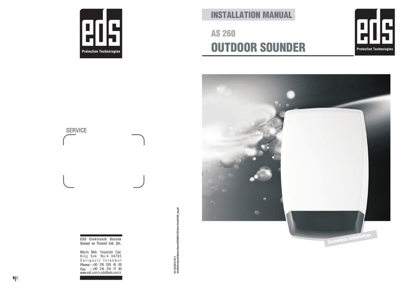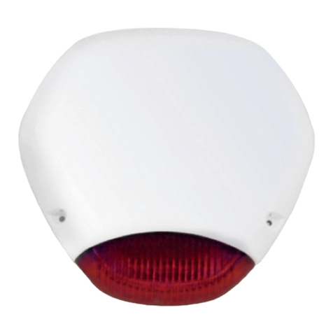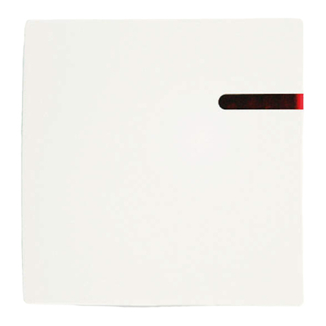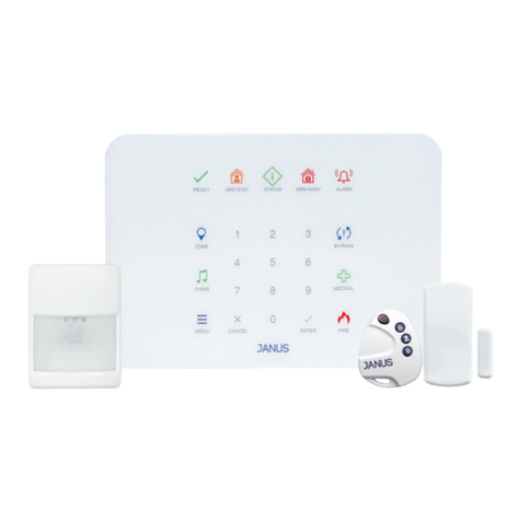
AS495L
Intrusion Alarm Systems / Outdoor Sounder
SPECIFICATIONS PHYSICAL
CONNECTIONS
Model AS495L
Environmental class IV Outdoor
Elektrical
Supply voltage range 10 - 15V DC
Stand-by current <70mA
Alarm current <1100mA
Audio output 110dB
Audio frequency 2-4Khz
Audio type 4 Optional
Time selection 4
Start time set-up 5min. (selectable)
Sounder time 5/15min. (selectable)
Sounder Type Horn type
Trigger type Negative / Positive
Flasher Power LED
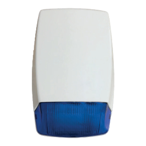
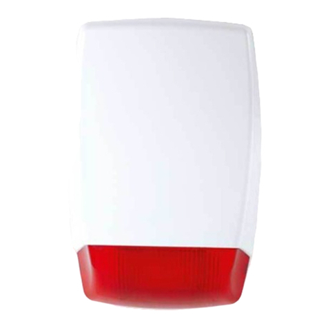
Flasher color Red / Blue / Orange
LED Indicator
Double LED with flasher
Tamper Avaliable
Metal inner cover Avaliable
Battery / Accumulator Accumulator 12V-1.2A / 2.2A /7A
Accumulator slot Avaliable (12V 1.2Ah/2.2Ah/7Ah)
General
Housing material ABS Plastic
Housing shape Square
Extrenal cover color White
Protection class IP44
Operating Temperature -10OC~+50OC
Dimension (HxWxD) 235x240x90mm
Weight 2.1kg
Year of Manufacture The year and week of manufacture is included in the rst
four digit of your product serial number (located on the
product identication label)
Manufacturer EDS Elektronik Destek Sanayi ve Ticaret Ltd.
Meclis Mah. Teraziler Cad. Hayran Sk. No: 4 34785
Sancaktepe / İstanbul / Turkey
Recycle
02/03/2017
R3
Address:
Meclis Mah. Teraziler Cad. Hayran Sk. No: 4 34785 Sancaktepe / İstanbul / Turkey +90 216 528 45 00 I [email protected] I www.eds.com.tr235 90
240
1Power LED Flasher
1
Electrical Connections
A
A
B
B
C
C
D
D
E
E
F
F
G
GSpeaker
Flasher
Tamper
Power Supply
Sounder Trigger
Flasher Trigger
Accumulator
Note: Open protective metal cover.
Adjust trigger and time before feeding.
Battery inverse connection protective fuse is 2A. If the battery is
mounted inversely, the fuse fails. When the connection adjusted
accurately, the fuse will be its regular position.
Jumper Fonksiyon
JP1-JP2 Time Select
JP3 Start time set-up
JP4 - JP5 Audio Select
JP6 Trigger Select
JP 3 Delay
Off 5min.
On -
Cable Connection
Red FL+
White FL-
Black 12V-
JP2 JP3 Time
Off Off 3min.
Off On 5min.
On Off 10min.
On On 15min.
JP6 Trigger
On Negative
Off Pozitive
Flasher Connection
Mount flasher as the LEDs looking downward.
Panel Connection
CADDX NX 4/6/8 AUX Programming:
* 8 9 7 1 3 0 (Entering to programming
mode)
47 # (Location (Menu) No)
7 * (Exit Programming mode)
max.0 - 255dk * (Time for exit activa-
tion between 0-225 min)
46 #1 *** (Exit Program)


