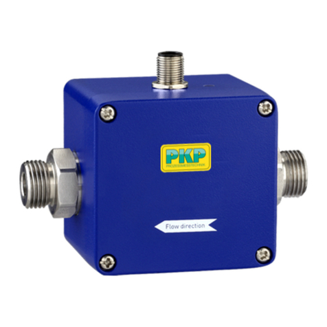
PKP DU06 Series User manual

Instruction Manual
DU06
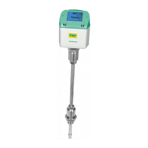
Ultrasonic flowmeter with display
PKP Prozessmesstechnik GmbH
Borsigstraße 24
D-65205 Wiesbaden- ordenstadt
Tel.: ++49-(0)6122-7055-0
Fax: ++49-(0)6122-7055-50
Email: [email protected]

Table of Contents
Safety Information................................................................................................................................2
Functional description..........................................................................................................................3
Installation location..............................................................................................................................3
Electrical connection............................................................................................................................4
Menu navigation...................................................................................................................................5
Output parameter <Output Parms> Menu 1.........................................................................................5
Instrument parameter <Instrument Parms> Menu 2.............................................................................7
Mathematical parameters <Math.Parms> Menu 3...............................................................................9
Instrument test function <Instr. Test> Menu 4...................................................................................10
Error messages....................................................................................................................................11
Functional check.................................................................................................................................11
Safety Information
General Instructions
To ensure safe operation, the device should only be operated according to the
specifications in the instruction manual. The requisite Health & Safety regulations for a
given application must also be observed. This statement also applies to the use of
accessories.
Every person who is commissioned with the initiation or operation of this device must have
read and understood the operating instructions and in particular the safety instructions!
The liability of the manufacturer e pires in the event of damage due to improper use, non-
observance of this operating manual, use of insufficiently qualified personnel and
unauthorized modification of the device.
Proper Usage
The ultrasonic flow meter Du06 are designed to measure the flow of liquids which do not
attack the device materials. All other usage is regarded as being improper and outside the
scope of the device.
In particular, applications in which shock loads occur (for e ample, pulsed operation)
should be discussed and checked in advance with our technical staff.
The series DU06 flow meter devices should not be deployed as the sole agents to prevent
dangerous conditions occurring in plant or machinery. Machinery and plant need to be
designed in such a manner that faulty conditions and malfunctions do not arise that could
pose a safety risk for operators.
Dangerous substances
For dangerous media such as e.g. O ygen, Acetylene, flammable or to ic substances as
well as refrigeration systems, compressors, etc. must comply with the relevant regulations
beyond the general rules.
DU06 Instruction manual 09/2019 page 2

Qualified Personnel
The DU06 devices may only be installed by trained, qualified personnel who are able to
mount the devices correctly. Qualified personnel are persons, who are familiar with
assembling, installation, placing in service and operating these devices and who are
suitably trained and qualified.
Inward Monitoring
Please check directly after delivery the device for any transport damages and deficiencies.
Additional with reference to the accompanying delivery note the number of parts must be
checked.
Claims for replacement or goods which relate to transport damage can only be considered
valid if the delivery company is notified without delay.
unctional description
The DU06 detects flow and accumulated volume in pipe systems due to ultrasonic delay
time mode with a time resolution of 45 pico seconds.
Different connection versions are available:
-½“ version made of brass or stainless steel, flow ma . 80 l/min
-1” version made of stainless steel, flow ma . 180 l/min
-2” version made of stainless steel, flow ma . 1000 l/min
All versions come with e ternal thread connection for mounting in pipe systems
Medium: Water, oil, emulsion etc. with low gas rate (bubbles)
Installation location
In order to avoid turbulence and cavitation, the largest possible distance to valves, pipe
bends, fittings and other flow disturbing elements must be maintained. In particular valves
can disturb the flow and lead to malfunction. Therefore, they must be installed in the flow
direction after the meter. Thus, the resulting interference is only generated after the DU06.
To avoid pressure surges, it is important that the valves are opened as slowly as possible.
In order to maintain proper functioning of the units, it is recommended to provide a straight
calming section of appro . 10 d on the inlet side and 5 d on the outlet side. (d = tube
inside diameter)
DU06 Instruction manual 09/2019 page 3

Electrical connection
Attention: Prior to the electrical connection of the device, it must be ensured that the sup-
ply voltage matches that required and the supply voltage is switched off.
Plug arrangement
Power supply, current-, voltage-, frequency output
4 pole plug (included in delivery)
Pin 1: 4-20mA / 0-10V / Freq.Out
Pin 2: GND
Pin 3: GND
Pin 4: +24VDC +/-15%
Relay outputs
6-pol plug (included in delivery)
Pin 1: Relay 2, normally open contact
Pin 2: Relay 2, middle contact
Pin 3: Relay 2, normally close contact
Pin 4: Relay 1, normally open contact
Pin 5: Relay 1, middle contact
Pin 6: Relay 1, normally close contact
DU06 Instruction manual 09/2019 page 4

Menu navigation
By help of a menu system the user can adapt the device to his application. The Menu has
a simple structure and is easy to handle. The button <P> activates the menu. With the
button <Arrow up > respectively <Arrow down > you can choose one or the four menu
points
•Output Parms
•Instrument Parms
•Math Parms
•Instrument Test
Pressing button <P> the menu point marked with<*>is activated. Using button<arrow up >
respectively. <arrow down >Parameters can be adjusted now. By pressing <P> selected
data is stored. All data is stored in a fi ed memory.
Attention:
Changing of parameters have to be confirmed by pressing <P> within 5 sec. otherwise the
DU06 changes back to the measuring modus without taking over the Parameters.
Advice:
Parameters which are critical to the system are protected by a code to prevent the func -
tion of the transmitter. This code is available from the manufacturer.
Output parameter <Output Parms> Menu 1
Relay 1 –setting switch point of relay 1
Relay 2 –setting switch point of relay 2
If the actual measured flow e ceeds/falls below one of the adjusted switch points the re-
lated relay is actuated. If switch point is adjusted to 0 the relay never is actuated.
Used relays are SPDT types with following switching performance:
30 VDC / 1 A respectively 120 VAC / 1 A resistive load.
U-I- Output – Selection of current, voltage or frequency output
4-20 mA: analogue current output 4-20 mA, working resistance 0 Ohm to 1000 Ohm
0-10 V: analogue voltage output 0-10 V, Ripple ca. 1 MOhm
Freq.Out: Configurable frequency output with Fma up to 32 KHz, Ripple ca. 2 KOhm
Electrical connection is made at two pins of the 4 pole supply plug. All output signals are
related to the device ground.
If the frequency output is selected, so it is possible to adjust the required frequency range
out-Max from 125 Hz <= Fout <= 32 KHz . The signal shape is rectangular with an amp-
litude of ca. 16 Vpp at a working voltage of 24 VDC and a load of 4.7 KOhm.
DU06 Instruction manual 09/2019 page 5

Maximum flow limit - Max low Limit
This parameter dedicates, at which flow the ma . value of the selected output signal is
created. (4-20 mA, 0-10 V, Fout). So it is possible to adapt the upper limit of the measur -
ing range to the individual requirement. If the Max low Limit is achieved, the selected
output delivers its ma imal signal.
Advice:
If the Max low Limit is passed, display shows <Overflow> and the different output sig-
nals react as follows:
4-20mA → 24 mA is generated
0-10V → 12 V is generated
Freq.Out → out-Max is shown
If flow is smaller than 0 respectively reversed output signals react as follows:
4-20mA → 4 mA is generated
0-10V → 0 V is generated
Freq.Out → 0 Hz is generated
Assignment of analog output signal
If the analogue output is used, the following assignment must be observed. 20 mA
corresponds to the Max low Limit 4 mA corresponds to all values below the Low low
Cut-Off. The initial value of the measuring range can be calculated with the following
formula.
X = (D / Dma + 0.25) / 0.0625
D = measuring range initial value
Dma . = Full scale value
X = mA value at the start of the measuring range
For e ample: DU06 factory setting. Measuring range initial value 1 l/min,
full scale value 180 l/min
(1/180 + 0.25) / 0.0625 = 4.089 mA
This means that 180 l/min corresponds to 20 mA, 1 l/min to 4.089 mA and 0.99 l/min to
less than 4 mA.
0 on the remote display corresponds to 4 mA.
In this way a linear assignment of the analog signal to the flow value is achieved.
DU06 Instruction manual 09/2019 page 6

Instrument parameter <Instrument Parms> Menu 2
DU06 Modus, low meter - Totalisator - DU06 Mode
low: the device works as flow meter
Totalize: the device works as totalizer
The added value of the totalizer is still achieved in case of power failure.
A power failure can be indicated but the function Bat Check.
Advice:
The totalizer always works even if the DU06 don’t work in mode Totalize.
Within device mode Totalize the added sum can be deleted by pressing <arrow up>.
low-Units Select low Unit
Available Flow Units:
l/sec - Litre per second
l/min - Litre per minute
l/h - Litre per hour
m³/min - Cubic meter per minute
m³/h - Cubic meter per hour
gal/sec - Gallons per second
gal/min - Gallons per minute
gal/h - Gallons per hour
%- Percent from Max low Limit
m/sec - Flow speed in meter per second
Advice:
If DU06 is in measuring mode, you will see the actual speed of flow when you press <Ar-
row up>. Pressing <Arrow down> the speed of sound in the media in m/sec is indicated.
low direction- Reverse low
Reverse low negates the prefi of flow indication
DU06 indicates no negative flow, so if there is after installation 0 flow indication
while there is flow, flow direction has to be reversed by reverse flow function!
DU06 Instruction manual 09/2019 page 7

Leak flow volume cut off - Low low Cut-Off
If the absolute value of flow is smaller than Max low Limit * Low_ low_Cut_Off, indic-
ated flow value is 0. Low flow cut off can be adjusted between 0 % and 10 % of Max low
Limit.
It is recommended to adjust at least 1-2 %.
Checking power value - BatCheck
If BatCheck is activated, a possible power failure is registered. If power comes back an
alert is sounding and the message <Pwr.Supply fail> is appearing. It is necessary to
press <P> and <arrow up>at the same time to get back to the standard measuring mode.
This function is recommended to use when totalizator is in operation and shall inform the
user that it could be that due to the power failure totalizator level is not correct because
flow passing the DU06 during power failure was not counted.
Parameter protection - Pin
Pin Code is for protecting parameter of the device. Changing them without authority will be
avoided. If the Pin is activated DU06 requires the 4 digit pin if anybody tries to e change
any parameter. The Pin function is working until it is de-activated
Advice:
It is recommended to make a note of the code a save location. If the Pin is forgotten user
has to ask
at the manufacturer for a master-pin.
Interface RS-232 or RS-485 – COM Interface
For selection of following interface standards: RS-232 or RS-485.
Following options are available:
DU06 with RS-232
DU06 with RS-485, Half Duple
Advice:
If you use RS-485 interface , DU06 demands for a valid Bus address.
Restore of actory Settings – Restore actory Settings
Puts back the DU06 into the condition of delivery due to manufacturer (software adjust-
ment).
DU06 Instruction manual 09/2019 page 8

Mathematical parameters <Math.Parms> Menu 3
Characteristic diagram K- actor – K- actor
This function is used for adaption of the characteristic diagram up to formula
Qkorr = Qist K;
Qist -measured flow;
Qkorr -corrected flow;
K - absolute term (multiplicative)
It is used if flow conditions have changed referring to the original calibration
Advice:
This function is protected due to a separate Code (KO_Code). If the code is required
please ask
For it at the manufacturer
Characteristic diagram dynamical offset – Dynamical Offset
This function is used for adaption of the characteristic diagram up to formula:
Qkorr = Qist + DynOffset (Qist/QmaxPhys);
With: Qist -measured flow;
Qkorr -corrected flow;
Qma Phys - ma . flow in pipe at v=5m/sec
DynOffset - absolute term (additive)
Advice:
This function is protected due to a separate Code (KO_Code). If the code is required
please ask for it at the manufacturer
Integration Time
The DU06 needs for one flow measurement appro . 80 ms. It calculates the indicated flow
out of a minimum of 10 und ma . 100 measures. This means an adjustment range of the
Integration Time of 0,8 sec until 8 sec. The average value is detected by the method of
moving e ponential average value.
DU06 Instruction manual 09/2019 page 9

Instrument test function <Instr. Test> Menu 4
Indication of supply voltage - Supply Voltage
The device works like a Voltmeter and indicates the actual supply voltage.
Puss button <P> to finish the measurement.
Advice!
The allowed voltage is: 24 VDC +/-15 %, ma . Ripple 100 mV
If low-grade power supply units are used, restricted function of the DU06 respectively inac-
curate
Measurement can appear. It is forbidden to operate inductive load with the same power
supply than the DU06
4-20 mA offset of analog output - 4-20 mA Offset
This function is for special applications and protected due to manufacturers code.
4-20 mA K-value of current output - 4-20 mA K-Value
This function is for special applications and protected due to manufacturers code.
0-10 V K-value of voltage output- 0-10 V K-Value
This function is for special applications and protected due to manufacturers code.
low test function - low Test
This function simulates flow rates between zero and Max low Limit, for demonstration
and test purposes during configuration of the plant. The display, the relays contacts as
well as 4-20 mA, 0-10 V, Fout and the interface is operated. Thereby the DU06 works
without pipe and media.
Relays Test unction – Relays Test
Relays test function operates the relays alternating (relays on/off) 5.
DU06 Instruction manual 09/2019 page 10

Error messages
Error 1: Echo Bad
Very turbulent flow, or too high air content in the medium; no measurement possible.
The reason may be that the medium generally has a high proportion of air, or the propor-
tionate air
is dispensed by turbulence in the measuring system. See point 6 (Selection of the installa-
tion location).
Error 2: No Fluid
No media in measuring pipe. No measurement is possible. Fill system with medium.
The DU06 indicates no negative flow. If there is 0 flow indication while there is flow, flow
direction has to be changed in the program.
unctional check
It is the responsibility of the operator to test the function periodically and to check the de -
vice visually. periodically perform a functional test or a visual inspection.
A functional test of the contacts can be carried out in the installed or removed state, with
manual displacement of the float or by filling the container. It should be noted that no func -
tional processes are triggered by the functional test.
DU06 Instruction manual 09/2019 page 11

Flow Measurement and Monitoring
DU06
Ultrasonic- Flowmeter
and Counter with Local
Indication
•heavy duty meter, brass- and
stainless steel version
•or 1/2“ to 2“ pipes
•very broad measurement range:
0,5...80 to 8...1000 l/min
•2-line LCD-display or low
and total indication
•output signals: 4...20 mA,
0...10 V or low,
pulses or total
•Pmax: 25 bar, Tmax: 100 °C
Description:
The DU06 flowmeter is fitted with two ultrasonic sensors that
are facing each other. The echo travel time is a function of the
flow rate. The sensors act alternately as transmitter and
receiver.
The echo time difference is proportional to the flow rate. In
contrast to other types of ultrasonic flowmeters, the sensors
are oriented parallel to the flow stream. This results in an
extremely compact meter which is highly accurate, has
outstanding turndown ratio dynamics and can monitor and
meter very high flow rates without any reduction in pipe
cross-sectional area.
Typical applications:
The DU06 measures, monitors and totali es liquid flow.
Among the applications for this device are cooling systems
(water / glycol mixtures), non-conductive products (demineral-
i ed water, low viscous oils) and chemically aggressive and
caustic liquids.
PKP Prozessmesstechnik GmbH
Borsigstr. 24 • D-65205 Wiesbaden
S +49 (0) 6122-7055-0 • T +49 (0) 6122 7055-50
[email protected] • www.pkp.de
20190911

Models:
DU06.M… brass version, housing made of brass
2.0401, sensors made of stainless steel
1.4571, FKM gaskets, (EPDM optional),
for 1/2" pipe only
DU06. … stainless steel version, housing made of
stainless steel 1.4571, sensors made of
stainless steel 1.4571, FKM gaskets,
(EPDM optional), for 1/2" to 2" pipe
Measuring ranges:
Measuring
range *)
Brass-
version
St. steel-
version
Process-
connection
0,5…80 l/min DU06.M…R015 DU06.E...R015 R 1/2 male
1…180 l/min -DU06.E…R025 R 1 male
8…1000 l/min -DU06.E…R050 R 2 male
*) Maximum ranges are specified. For a higher resolution the
output can be programmed for end values < max. measuring
range
Electrical Data:
Output signal: adjustable on site: 4...20 mA, 0...10 V
or frequency output
and 2 limit relays
Connection 4 pin plug: Power supply, output signal
Pin 1: 4-20 mA / 0-10 V / frequency output
Pin 2: GND
Pin 3: GND
Pin 4: +24 VDC ±15%
Connection 6 pin plug: Relay output
Pin 1: relay 2, N/O contact
Pin 2: relay 2, common contact
Pin 3: relay 2, N/C contact
Pin 4: relay 1, N/O contact
Pin 5: relay 1, common contact
Pin 6: relay 1, N/C contact
Dimensions:
Order Code:
Order number: DU06.
Ultrasonic flowmeter and counter
with local indication
. V. R025. 0. 0
Material version:
M = brass housing, sensors st. steel
(with R ½ male connection only)
E = st. steel housing, sensors st. steel
S = special version
Gaskets:
V = FKM (standard)
E = EPDM
S = special gasket
Measuring range / Process connection:
R015 = 0,5…80 l/min, R ½ male
R025 = 1…180 l/min, R 1 male (only DU06.E…)
R050 = 8…1000 l/min, R 2 male (only DU06.E…)
Output signal:
0 = universal output for power, voltage or frequency,
adjustable on site
and 2 limit relays
Options:
0 = without
9 = please specify in plain text
Technical Data:
Max. pressure: 25 bar
Medium temperature: −20...+100 °C
Ambient temperature: −10...+60 °C
Accuracy: ± 2% of full scale
Mounting position: any, rotatable housing
Medium: acoustically conductive liquids,
solids content < 10 Vol.%
Power supply: 24 VDC ± 15%
Power consumption: 200 mA max.
Outputs: 4…20 mA, 0…10 V, frequency-
output (programmable,
max. 32 kH ),
Ri = 2 kOhm
Limit value relay: 2 x changeover cont., 30 VDC / 1 A
Display: LCD, 2 x 16 digit, illuminated
Protection class: IP65
Response time: 0,8...8 s, factory setting ca. 1,6 s
Flow direction: adjustable in device
PKP Prozessmesstechnik GmbH
Borsigstr. 24 • D-65205 Wiesbaden
S +49 (0) 6122-7055-0 • T +49 (0) 6122 7055-50
[email protected] • www.pkp.de
This manual suits for next models
3
Table of contents
Other PKP Measuring Instrument manuals