manuals.online logo
Brands
  1. Home
  2. •
  3. Brands
  4. •
  5. Edwards
  6. •
  7. Security Sensor
  8. •
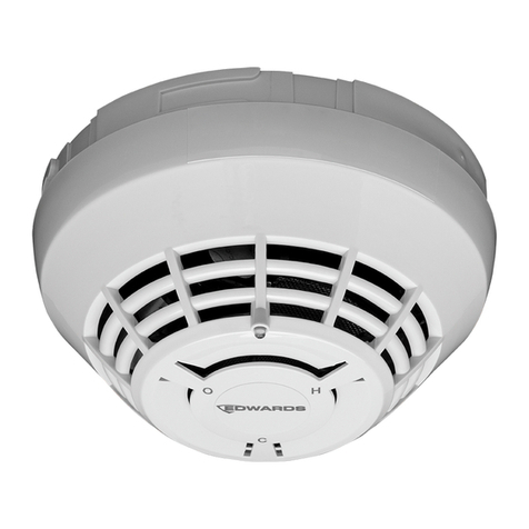
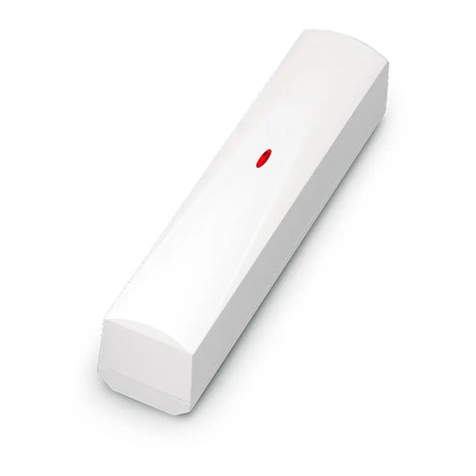
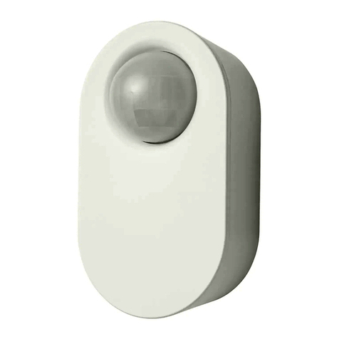
  9. Edwards SIGA2-HRS Owner's manual

Edwards SIGA2-HRS Owner's manual

12-18-17
Page 1 of 4 DATA SHEET E85001-0620
Not to be used for installation purposes. Issue 1
EDWARDS®Catalog Intelligent Initiating Devices
LIFE SAFETY & INCIDENT MANAGEMENT
Overview
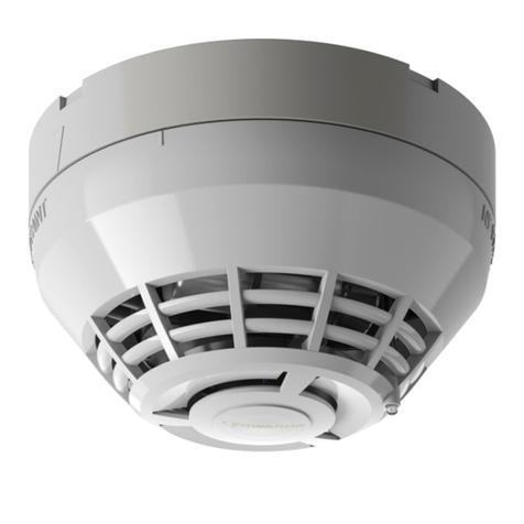
Signature Series fixed temperature and rate-of-rise heat detec-
tors bring advanced sensing technology to a practical design
that increases efficiency, saves installation time, cuts costs, and
extends property protection capabilities. Continuous self-diagnos-
tics ensure reliability over the long-haul, while the latest thermister
technology makes these detectors ideal whereever dependable
heat detection is required. With their modular CO sensor, these
devices pull double-duty — continually monitoring the environ-
ment for heat from combustion, as well as its invisible yet deadly
companion, carbon monoxide.
Like all Signature Series detectors, these are intelligent device
that gather analog information from their heat and CO sensor (if
present), converting this data into digital signals. To make an alarm
decision, the detector’s on-board microprocessor measures and
analyzes sensor readings and compares this information to histori-
cal data. Digital filters remove signal patterns that are not typical of
fires, thus virtually eliminating unwanted alarms.
The SIGA2-HCOS is a fixed temperature heat detector that
includes an advanced carbon monoxide sensor and daughter-
board. When the electrochemical cell reaches its end of life after
approximately six years, the detector signals a trouble condition
to the control panel. The sensor/daughterboard module is field-
replaceable.
Standard Features
Note: Some features described here may not be supported by
all control systems. Check your control panel’s Installation and
Operation Guide for details.
• Fixed temperature or rate-of-rise heat detection with optional
carbon monoxide sensor
• Field-replacable carbon monoxide sensor/daughterboard
module
• Uses existing wiring
• Automatic device mapping
• Ground fault detection by module
• Up to 250 devices per loop
• Non-volatile memory
• Electronic addressing
• Bicolor (green/red) status LED
• Standard, relay, fault isolator, and audible mounting bases
• 50 foot (15.2 meter) spacing
• 15 °F (9 °C) per minute rate-of-rise alarm point (HRS)
• 135 °F (57 °C) fixed temperature alarm point (HFS/HRS/HCOS)
Intelligent Heat
Detectors with
Optional
CO Sensors
SIGA2-HFS, SIGA2-HRS, SIGA2-HCOS
5278-1657:
0300 S853
Page 2 of 4 DATA SHEET E85001-0620
Not to be used for installation purposes. Issue 1
Application
Heat detection
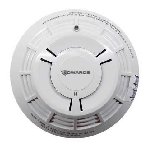
SIGA2-HRS combination fixed temperature/rate-of-rise heat de-
tectors provide a 15 °F (9 °C) per minute rate-of-rise heat sensor
for the detection of fast-developing fires, as well as a 135°F (57°C)
fixed temperature sensor for slow building-fires. The heat sensor
monitors the temperature of the air and determines whether an
alarm should be initiated.
SIGA2-HFS and SIGA2-HCOS fixed temperature heat detectors
provide a 135°F (57°C) fixed-temperature heat sensor for the detec-
tion of heat due to fire. The heat sensor monitors the temperature of
the air and determines whether an alarm should be initiated.
Carbon monoxide detection
The SIGA2-HCOS includes a replaceable chemical cell for the de-
tection of carbon monoxide (CO). CO detection has rapidly become
a standard part of life safety strategies everywhere. Monitored CO
detection is becoming mandated with increasing frequency in all
types of commercial applications, but particularly in occupancies
such as hotels, rooming houses, dormitories, day care facilities,
schools, hospitals, assisted living facilities, and nursing homes. In
fact, more than half of the U.S. population already lives in states
requiring the installation of CO detectors in some commercial occu-
pancies. This is because carbon monoxide is the leading cause of
accidental poisoning deaths in America. Known as the “Silent Killer,”
CO is odorless, tasteless, and colorless. It claims nearly 500 lives,
and results in more than 15,000 hospital visits annually.
Installation
Signature Series detectors
mount to North American
1-gang boxes, 3-1/2 inch
or 4 inch octagon boxes,
and to 4 inch square electri-
cal boxes 1-1/2 inches (38
mm) deep. They mount to
European BESA and 1-gang
boxes with 60.3 mm fixing
centers. See mounting base
installation and wiring for
more information.
Testing & Maintenance
The user-friendly maintenance program shows the current state
of each detector and other pertinent messages. Single detectors
may be turned off temporarily from the control panel. Availability
of maintenance features is dependent on the fire alarm system
used. When the CO sensor’s electrochemical cell reaches its end
of life, the detector signals a trouble condition to the control panel.
The sensor/daughterboard module is field-replaceable. Scheduled
maintenance (Regular or Selected) for proper detector operation
should be planned to meet the requirements of the Authority Hav-
ing Jurisdiction (AHJ). Refer to current NFPA 72, NFPA 720, and
ULC CAN/ULC 536 standards.
Compatibility
SIGA2 series detectors are compatible only with the Signature
Loop Controller.
Sensing and reporting technology
The microprocessor in each detector provides four additional ben-
efits - Self-diagnostics and History Log, Automatic Device Map-
ping, and Fast, Stable Communication.
Self-diagnostics and History Log - Each Signature Series
detector constantly runs self-checks to provide important mainte-
nance information. The results of the self-check are automatically
updated and permanently stored in the detector’s non-volatile
memory
Automatic Device Mapping - The loop controller learns where
each device’s serial number address is installed relative to other
devices on the circuit. The mapping feature provides supervision
of each device’s installed location to prevent a detector from being
reinstalled (after cleaning etc.) in a different location from where it
was originally.
Fast Stable Communication - On-board intelligence means less
information needs to be sent between the detector and the loop
controller. Other than regular supervisory polling response, the
detector only needs to communicate with the loop controller when
it has something new to report.
Accessories
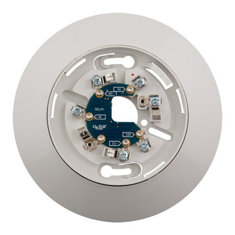
Detector mounting bases have wiring terminals that are acces-
sible from the “room-side” after mounting the base to the electrical
box. The bases mount to North American 1-gang boxes and to
3½ inch or 4 inch octagon boxes, 1½ inches (38 mm) deep. They
also mount to European BESA and 1-gang boxes with 60.3 mm
fixing centers. The SIGA-SB4, SIGA-RB4, and SIGA-IB4 mount to
North American 4 inch sq. electrical boxes in addition to the above
boxes. They include the SIGA-TS4 Trim Skirt which is used to
cover the “mounting ears” on the base. The SIGA-AB4G mounts
to a 4” square box only.
SIGA-IB
Isolator Base
SIGA-LED
Remote LED
SIGA-RB
Relay Base
SIGA-SB
Standard Base
SIGA-AB4G/T/LF
Audible Base
Remote LED SIGA-LED - The remote LED connects to the
SIGA-SB or SIGA-SB4 Standard Base only. It features a North
American size 1-gang plastic faceplate with a white finish and red
alarm LED.
SIGA-TS4 Trim Skirt - Supplied with 4 inch bases, it can also
be ordered separately to use with the other bases to help hide
surface imperfections not covered by the smaller bases.
SIGA-AB4G and SIGA-AB4GT - These sounder bases are de-
signed for use where localized or group alarm signaling is required.
The SIGA-AB4G is compatible with Signature Series smoke and
heat detectors. The SIGA-AB4GT sounder base, when used with
the SIGA-TCDR Temporal Pattern Generator module, adds an
audible output function to any Signature Series detector, including
fire and CO detectors.
Installation
1
2
1. Tamper-resist lever arm on base
(Break off to disable.)
2. Access slot for tamper-resist mechanism
Page 3 of 4 DATA SHEET E85001-0620
Not to be used for installation purposes. Issue 1
Typical Wiring
The detector mounting bases accept #18 AWG (0.75mm2), #16
(1.0mm2), #14 AWG (1.5mm2), and #12 AWG (2.5mm²) wire sizes.
Note: Sizes #16 AWG (1.0mm2) and #18 AWG (0.75mm2) are
preferred for ease of installation. See Signature Loop Controller
catalog sheet for detailed wiring requirement specifications.
Audible Detector Base, SIGA-AB4G
This base is designed for use where localized or group alarm sig-
naling is required. When the detector senses an alarm condition,
the audible base emits a local alarm signal. The optional SIGA-CRR
Polarity Reversal Relay can be used for sounding to other audible
bases on the same 24 Vdc circuit.
SIG+ SIG-
DATA-
OUT
DATA-
IN
DATA+
IN/OUT
24 Vdc in
From power supply or
previous base
Datain
From Signature controller or
previous device
24 Vdc out
To next base or EOL relay
Data out
To next Signature device
+
-
+
-
Volume setting
Default=High volume
Cut for low volume
Tone setting
Default =Temporal pattern
Cut for steady tone
+
-
+
-
To configure output volume
or tone, cut the circuit board
as shown.
Relay and Audible Bases operate as follows:
- at system power-up or reset, the relay is de-energized
- when a detector is installed in the base with the power
on, the relay energizes for four seconds, then de-energizes
- when a detector is removed from a base with the power on,
the relay is de-energized
- when the detector enters the alarm state, the relay is energized.
Standard Detector Base, SIGA-SB, SIGA-SB4
This is the basic mounting
base for EDWARDS Signature
Series detectors. The SIGA-LED
Remote LED is supported by the
Standard Base.
Term Description
1 Not Used
2 DATA IN/OUT (+)
3 Not Used
4 DATA IN (-)
4 Remote LED (-)
5 Remote LED (+)
6 Not Used
7 DATA OUT (-)
Max resistance
per wire
must not exceed
10 Ohms
DATA IN (-)
DATA IN (+)
From Signature Controller
or Previous Device
DATA OUT (-)
DATA OUT (+)
To Next Device
Remote LED
Relay Detector Base, SIGA-RB, SIGA-RB4
This base includes a relay. Nor-
mally open or closed operation
is selected during installation.
The dry contact is rated for 1 amp
(pilot duty) @ 30 Vdc. The relay’s
position is supervised to avoid ac-
cidentally jarring it out of position.
The SIGA-RB can be operated as
a control relay if programmed to
do so at the control panel (EST3
V.2 only). The relay base does not
support the SIGA-LED Remote
LED. CONTACT RATING
1.0 Amp @ 30 VDC
(Pilot Duty)
Term Description
1 Normally Open
2 DATA IN/OUT (+)
3 Common
4 DATA IN (-)
5 Not Used
6 Normally-Closed
7 DATA OUT (-)
Isolator Detector Base, SIGA-IB, SIGA-IB4
This base includes a built-in line fault isolator for use on Class A
circuits. A detector must be installed for it to operate. The isolator
base does not support the SIGA-LED Remote LED.
The isolator operates as follows:
- a short on the line causes all iso-
lators to open within 23 msec
- at 10 msec intervals,
beginning on one side
of the Class A
circuit nearest the loop
controller, the isolators
close to provide the
next isolator down the
line with power
- when the isolator next to
the short closes, reopens within 10 msec.
The process repeats beginning on the
other side of the loop controller.
Term Description
1 Not Used
2 DATA IN/OUT (+)
3 DATA IN (-)
4 Not Used
5 Not Used
6 DATA OUT (-)
7 Not Used
Audible Detector Base for CO
and Fire Detectors, SIGA-AB4GT
The Signature Series AB4GT sounder base, when used with the
SIGA-TCDR Temporal Pattern Generator, adds an audible output
function to any Signature Series detector. For more information on
this device, refer to DATA SHEET E85001-0623 -- Sounder Base
for CO and Fire Detectors.
TCDR Riser +
TCDR Riser -
SLC +
SLC -
TCDR Riser +
TCDR Riser -
SLC +
SLC -
4
1. Volume setting. Default is high volume. For low volume, cut trace per item 4.
2. Reserved for future use. Do not cut.
3. Reserved for future use. Do not cut.
4. To configure output volume, cut trace as shown.
5. To next SIGA-AB4GT sounder base or EOL relay.
6. SLC_OUT to next intelligent addressable device.
7. SLC_IN from intelligent addressable controller or previous device.
8. From SIGA-TCDR Temporal Pattern Generator or previous SIGA-AB4GT
sounder base.
12-18-17
Page 4 of 4 DATA SHEET E85001-0620
Not to be used for installation purposes. Issue 1
LIFE SAFETY & INCIDENT MANAGEMENT
Contact us...
Email: edwards.fi[email protected]
Web: edwards-fire.com
1016 Corporate Park Drive
Mebane, NC 27302
EDWARDS is a registered mark in the
United States and other countries.
© 2018 United Technologies Corporation.
All rights reserved.
Warnings & Cautions
• This detector does not operate without electrical power. As fires frequently cause
power interruption, discuss further safeguards with the local fire protection specialist.
• This detector does not sense fires in areas where heat cannot reach the detector.
Heat from fires in walls, roofs, or on the opposite side of closed doors may not reach
the detector.
• This heat detector by itself does not provide life safety protection Use this detector
with ionization and/or photoelectric smoke detectors.
• This detector does not detect oxygen levels, smoke, toxic gases, or flames. Use this
device as part of a broad-based life safety program which includes a variety of infor-
mation sources pertaining to heat and smoke levels, extinguishment systems, visual
and audible devices, and other safety measures.
• Independent studies indicate that heat detectors should only be used when property
protection alone is involved. Never rely on heat detectors as the sole means of fire
protection.
Specifications
SIGA2-HRS SIGA2-HFS SIGA2-HCOS
Normal operating current 45 µA 45 µA 45 µA
Standalone alarm current 18 mA 18 mA 18 mA
Alarm Current 45 µA 45 µA 45 µA
Rate-of-rise alarm point 15°F (9°C)/min. N/A N/A
Fixed temperature alarm point 130 to 140°F (54 to 60°C)
Operating voltage 15.20 to 19.95 VDC
Maximum spacing 50 ft. (15.2 m) centers*
Construction High impact engineering polymer
Mounting Plug-in
Shipping weight 0.44 lb. (164 g)
Compatible bases See Ordering Information
Operating environment 32 °F to 100 °F (0 °C to 38 °C), 0 to 93% RH, noncondensing
Storage temperature − 4 °F to 140 °F (− 20 °C to 60 °C)
*When replacing SIGA-HRS/HFS ensure spacing is 50ft or less.
Ordering Information
Catalog
Number Description Ship Wt.
lbs (kg)
SIGA2-HRS Intelligent combination fixed temperature/rate-of-rise heat detector 0.4 (0.16)
SIGA2-HFS Intelligent fixed temperature heat detector 0.4 (0.16)
SIGA2-HCOS Intelligent fixed temperature heat detector with CO sensor 0.4 (0.16)
SIGA2-HCOS-CA Intelligent fixed temperature heat detector with CO sensor
(for use in Canadian markets only) 0.4 (0.16)
Accessories
SIGA-SB Detector Mounting Base - Standard
0.2 (.09)
SIGA-SB4 4-inch Detector Mounting Base c/w Trim Skirt
SIGA-RB Detector Mounting Base w/Relay
SIGA-RB4 4-inch Detector Mounting Base w/Relay, c/w Trim Skirt
SIGA-IB Detector Mounting Base w/Fault Isolator
SIGA-IB4 4-inch Detector Mounting Base w/ Fault Isolator, c/w Trim Skirt
SIGA-LED Remote Alarm LED (not for EN54 applications)
SIGA-AB4G Audible (Sounder) Base for Fire Detectors 0.3 (0.15)
SIGA-AB4GT Audible (Sounder) Base for CO and Fire Detectors 0.3 (0.15)
SIGA-TCDR Temporal Pattern Generator 0.3 (0.15)
SIGA-TS4 Trim Skirt (supplied with 4-inch bases) 0.1 (.04)
2-CORPL Replacement CO Sensor 0.1 (.04)

This manual suits for next models

2

Other Edwards Security Sensor manuals

Edwards SIGA-PHDB Assembly instructions

Edwards

Edwards SIGA-PHDB Assembly instructions

Edwards SIGA-IM Assembly instructions

Edwards

Edwards SIGA-IM Assembly instructions

Edwards Signature Series Assembly instructions

Edwards

Edwards Signature Series Assembly instructions

Edwards SIGA-HRD Assembly instructions

Edwards

Edwards SIGA-HRD Assembly instructions

Edwards GasCheck G3 Magshield Installation and operating instructions

Edwards

Edwards GasCheck G3 Magshield Installation and operating instructions

Edwards SIGA-HRD Assembly instructions

Edwards

Edwards SIGA-HRD Assembly instructions

Edwards AB4G Assembly instructions

Edwards

Edwards AB4G Assembly instructions

Edwards 517FH Series User manual

Edwards

Edwards 517FH Series User manual

Edwards ELD500 Series User manual

Edwards

Edwards ELD500 Series User manual

Popular Security Sensor manuals by other brands

ABS ABS-Lock DH04 Series quick start guide

ABS

ABS ABS-Lock DH04 Series quick start guide

Innotech SENW51 manual

Innotech

Innotech SENW51 manual

NOMA 052-7801-8 instruction manual

NOMA

NOMA 052-7801-8 instruction manual

Renkforce 751559 operating instructions

Renkforce

Renkforce 751559 operating instructions

GST C-9103 quick start guide

GST

GST C-9103 quick start guide

ScienTECH Vector Series operating manual

ScienTECH

ScienTECH Vector Series operating manual

Teledyne Spyglass SG50 F IR3-V user manual

Teledyne

Teledyne Spyglass SG50 F IR3-V user manual

Toshiba RBC-RD1-PE owner's manual

Toshiba

Toshiba RBC-RD1-PE owner's manual

KingShield Orion OD102 quick start guide

KingShield

KingShield Orion OD102 quick start guide

Global Fire Equipment GFE-S Installation Wiring Diagram

Global Fire Equipment

Global Fire Equipment GFE-S Installation Wiring Diagram

Elkron EL50RT 4PH 250m installation manual

Elkron

Elkron EL50RT 4PH 250m installation manual

Emerson Machinery Health PR 9268 Series installation guide

Emerson

Emerson Machinery Health PR 9268 Series installation guide

Sulzer ABS CA 461 installation guide

Sulzer

Sulzer ABS CA 461 installation guide

EZiCAT EZiSYSTEM user manual

EZiCAT

EZiCAT EZiSYSTEM user manual

Smart Bridge Quick 9500N-000 install guide

Smart Bridge

Smart Bridge Quick 9500N-000 install guide

Gas Clip Technologies Multi Gas Clip user manual

Gas Clip Technologies

Gas Clip Technologies Multi Gas Clip user manual

Velleman ZLUV220 user manual

Velleman

Velleman ZLUV220 user manual

Honeywell Small SATCOM Operation, installation, and maintenance manual

Honeywell

Honeywell Small SATCOM Operation, installation, and maintenance manual

manuals.online logo
manuals.online logoBrands
  • About & Mission
  • Contact us
  • Privacy Policy
  • Terms and Conditions

Copyright 2025 Manuals.Online. All Rights Reserved.